Table of Contents
Advertisement
Quick Links
Advertisement
Table of Contents

Related Manuals for Supermicro X11DSF-E


Summary of Contents for Supermicro X11DSF-E
- Page 1 X11DSF-E USER’S MANUAL Revision 1.0a...
- Page 2 For more information, go to www.P65Warnings.ca.gov. The products sold by Supermicro are not intended for and will not be used in life support systems, medical equipment, nuclear facilities or systems, aircraft, aircraft devices, aircraft/emergency communication devices or other critical systems whose failure to perform be reasonably expected to result in significant injury or loss of life or catastrophic property damage.
- Page 3 SATA 3.0 ports, thirty-two possible NVMe slots (32x NVMe from PCI-E switch + 4x M.2 from PCH), and M.3 support. The cutting-edge X11DSF-E offers highly versatile SATA and NVMe options, with an array of flexible PCI-E solutions. This motherboard is optimized for storage-intensive systems, high-perfomance platforms, and demanding workloads.
- Page 4 Super Micro Computer, Inc. 980 Rock Ave. San Jose, CA 95131 U.S.A. Tel: +1 (408) 503-8000 Fax: +1 (408) 503-8008 Email: marketing@supermicro.com (General Information) support@supermicro.com (Technical Support) Website: www.supermicro.com Europe Address: Super Micro Computer B.V. Het Sterrenbeeld 28, 5215 ML...
-
Page 5: Table Of Contents
Preface Table of Contents Chapter 1 Introduction 1.2 Processor and Chipset Overview ..................17 1.3 Special Features ........................17 1.4 System Health Monitoring ....................18 1.5 ACPI Features ........................19 1.6 Power Supply ........................19 1.7 Super I/O ..........................19 1.8 Advanced Power Management ..................20 Chapter 2 Installation 2.1 Static-Sensitive Devices .....................21 2.2 Motherboard Installation .....................22 2.3 Processor and Heatsink Installation ...................24... - Page 6 Super X11DSF User's Manual Appendix A BIOS Codes A.1 BIOS Error POST (Beep) Codes ..................119 Appendix B Software Installation B.1 Installing Software Programs ...................121 B.2 SuperDoctor 5 .........................122 ® Appendix C Standardized Warning Statements Appendix D UEFI BIOS Recovery D.1 Overview ...........................126 D.2 Recovering the UEFI BIOS Image ...................126 D.3 Recovering the Main BIOS Block with a USB Device .............127...
-
Page 7: Chapter 1 Introduction
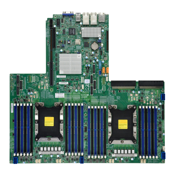
Chapter 1 Introduction Congratulations on purchasing your computer motherboard from an industry leader. Supermicro motherboards are designed to provide you with the highest standards in quality and performance. 1.1 Checklist This motherboard was designed to be used in an SMCI-proprietary chassis only as a part of an integrated, complete system solution. - Page 8 Super X11DSF-E User's Manual Figure 1-1. X11DSF-E Motherboard Image Note: All graphics shown in this manual were based upon the latest PCB revision avail- able at the time of publication of the manual. The components in the motherboard you received may or may not look exactly the same as the graphics shown in this manual.
- Page 9 Chapter 1: Introduction Figure 1-2. X11DSF-E Motherboard Layout (not drawn to scale) JUIDB2 JVGA1 LED1 JUSB1 LEDM1 USB2/3 JIPMILAN JLAN2 JLAN1 JSDCARD1 LED6 JBT1 JPQAT JUSBA1 USB7(3.0) BIOS LICENSE JSW0 BAR CODE PSU2 PSU1 X11DSF-E REV:1.00 IPMI CODE DESIGNED IN USA...
- Page 10 Super X11DSF-E User's Manual Quick Reference IPMI_LAN JUIDB2 JCOM1 LAN2 LAN1 JUSB1 JPB1 JUIDB2 LED1 JVGA1 LED1 JPG1 SXB1A JUSB1 LEDM1 USB2/3 JIPMILAN LEDM1 JLAN2 JLAN1 JSDCARD1 JPL1 JBT1 LED6 JSDCARD1 LED6 JWD1 SXB1B JRK1 JPME2 LED3 JBT1 JPQAT JPQAT...
- Page 11 Chapter 1: Introduction Quick Reference Table Jumper Description Default Setting JBT1 CMOS Clear Open (Normal) JPB1 BMC Enable/Disable Pins 1-2 (Enabled) JPG1 VGA Enable/Disable Pins 1-2 (Enabled) JPQAT1 QAT Enable/Disable Pins 2-3 (Disabled) when JPQAT1 is Enabled: JPQAT2 QAT Enable/Disable Pins 1-2 x16 Uplink Pins 2-3 x8 Uplink (Disabled) JPL1...
- Page 12 Super X11DSF-E User's Manual Connector Description PSU2 Power Supply Unit 2 S-SATA0/S-SATA1 (Powered) SATA connectors with power-pins built-in with support of SuperDOMs SXB1A WIO Left Riser slot (see note below) SXB1B WIO Right Riser slot (see note below) SXB1C Ultra Riser slot (see note below) PCI-E x32 Tray Cable connector interface (GPU, NVMe, M.3, or Ruler down device) (see note...
- Page 13 DIMM Size • Up to 128GB at 1.2V Note 1: Memory speed support depends on the processors used in the system. Note 2: For the latest CPU/memory updates, please refer to our website at http://www.supermicro.com/products/ motherboard. Chipset • Intel® C627 Expansion Slots •...
- Page 14 Super X11DSF-E User's Manual Motherboard Features Peripheral Devices • Two (2) USB 3.0 ports on the rear I/O panel (USB 3/4) • One (1) internal USB 2.0 header with (2) USB connections for front access (USB0/1) • One (1) internal USB header supports two USB 3.0 connections (USB5/USB6) BIOS •...
- Page 15 User's Guide available at http://www.supermicro.com/support/manuals/. Note 3: It is strongly recommended that you change BMC log-in information upon initial system power-on. The manufacture default username is ADMIN and the password is ADMIN. For proper BMC configuration, please refer to http://www.supermicro.com/ products/info/files/IPMI/Best_Practices_BMC_Security.pdf...
- Page 16 Super X11DSF-E User's Manual Figure 1-3. System Block Diagram NCSI DDR4 DDR4 AST2500 IPMI LAN RTL8211F RJ45 32MB COM1 UART FLASH LPC/eSPI 64MB BIOS FLASH Header USB2.0 [7] LPC/eSPI PE[5] PE[0..3] SLOT2 PE[6..9] SLOT3 Uplink X8 PCI-E /iSATA[0-7] I-SATA0~7 LAN1...
-
Page 17: Processor And Chipset Overview
1.2 Processor and Chipset Overview Built upon the functionality and capability of the Intel Xeon 81xx/61xx/51xx/41xx/31xx series processors (Socket P) and the Intel C627 chipset, the X11DSF-E motherboard provides superb system performance, scalable storage solutions, and a rich feature set based on cutting edge technology to address the needs of next-generation computer users. -
Page 18: System Health Monitoring
Super X11DSF-E User's Manual 1.4 System Health Monitoring This section describes the health monitoring features of the X11DSF-E motherboard. The motherboard has an onboard ASpeed AST2500 Baseboard Management Controller (BMC) that supports system health monitoring. Once a voltage becomes unstable, a warning is given or an error message is sent to the screen. -
Page 19: Acpi Features
Chapter 1: Introduction 1.5 ACPI Features ACPI stands for Advanced Configuration and Power Interface. The ACPI specification defines a flexible and abstract hardware interface that provides a standard way to integrate power management features throughout a computer system including its hardware, operating system and application software. -
Page 20: Advanced Power Management
Intel® QuickAssist Technology Built upon the architecture of Intel 81xx/61xx/51xx/41xx/31xx processors and the Intel C627 chipset, the X11DSF-E supports Intel® QuickAssist Technology (Intel QAT), which offers high-profile security and compression acceleration to standard server platforms in a software- defined infrastructure. -
Page 21: Chapter 2 Installation
Chapter 2: Installation Chapter 2 Installation 2.1 Static-Sensitive Devices Electrostatic Discharge (ESD) can damage electronic com ponents. To avoid damaging your motherboard and your system, it is important to handle them very carefully. The following measures are generally sufficient to protect your equipment from ESD. Precautions •... -
Page 22: Motherboard Installation
Super X11DSF-E User's Manual 2.2 Motherboard Installation All motherboards have standard mounting holes to fit different types of chassis. Make sure that the locations of all the mounting holes for both the motherboard and the chassis match. Although a chassis may have both plastic and metal mounting fasteners, metal ones are highly recommended because they ground the motherboard to the chassis. - Page 23 Chapter 2: Installation Installing the Motherboard 1. Install the I/O shield into the back of the chassis if needed. 2. Locate the mounting holes on the motherboard. See the previous page for the location. 3. Locate the matching mounting holes on the chassis. Align the mounting holes on the motherboard against the mounting holes on the chassis.
-
Page 24: Processor And Heatsink Installation
CPU socket cap is in place and that none of the socket pins are bent. Otherwise, please contact your retailer immediately. • Refer to the Supermicro website for updates on CPU support. • Please follow the instructions given in the ESD Warning section on the first page of this chapter before handling, installing, or removing system components. - Page 25 Chapter 2: Installation Overview of the Processor Socket Assembly The processor socket assembly contains 1) the Intel 81xx/61xx/51xx/41xx/31xx Processor 2) the narrow processor clip, 3) the dust cover, and 4) the CPU socket. 1. The 81xx/61xx/51xx/41xx/31xx Processor 81xx/61xx/51xx/41xx/31xx Processor 2. Narrow processor clip (the plastic processor package carrier used for the CPU) 3.
- Page 26 Super X11DSF-E User's Manual Overview of the Processor Heatsink Module (PHM) The Processor Heatsink Module (PHM) contains 1) a heatsink, 2) a narrow processor clip, and 3) 81xx/61xx/51xx/41xx/31xx processor 1. Heatsink 2. Narrow processor clip 3. The 81xx/61xx/51xx/41xx/31xx Processor Processor Heatsink Module (PHM)
- Page 27 Chapter 2: Installation Attaching the Processor to the Narrow Processor Clip to Create the Processor Package Assembly To properly install the CPU into the narrow processor clip, please follow the steps below. 1. Locate pin 1 (notch A), which is the triangle located on the top of the narrow processor clip.
- Page 28 Super X11DSF-E User's Manual Attaching the Processor Package Assembly to the Heatsink to Form the Processor Heatsink Module (PHM) After you have made a processor package assembly by following the instructions on the previous page, please follow the steps below to mount the processor package assembly onto the heatsink to create the Processor Heatsink Module (PHM).
- Page 29 Chapter 2: Installation Preparing the CPU Socket for Installation This motherboard comes with the CPU socket pre-assembled in the factory. The CPU socket contains 1) a dust cover, 2) a socket bracket, 3) the CPU (P0) socket, and 4) a back plate. These components are pre-installed on the motherboard before shipping.
- Page 30 Super X11DSF-E User's Manual Installing the Processor Heatsink Module (PHM) 1. Once you have assembled the Processor Heatsink Module (PHM) by following the instructions listed on page 29, you are ready to install the module into the CPU socket on the motherboard. To install the PHM into the CPU socket, follow the instructions below.
- Page 31 Chapter 2: Installation Removing the Processor Heatsink Module (PHM) from the Motherboard Before removing the Processor Heatsink Module (PHM), unplug power cord from the power outlet. 1. Using a T30 Torx-bit screwdriver, turn the screws on the PHM counterclockwise to loosen them from the socket, starting with screw marked #4 (in the sequence of 4, 3, 2, 2.
-
Page 32: Memory Support And Installation
DIMM modules to prevent any damage. Memory Support The X11DSF-E supports up to 3TB of 3DS LRDIMM/LRDIMM/3DS RDIMM/RDIMM/NV-DIMM DDR4 ECC 2666/2400/2133 MHz memory in 24 memory slots. Populating these DIMM modules with a pair of memory modules of the same type and size will result in interleaved memory, which will improve memory performance. - Page 33 Chapter 2: Installation DIMM Population Guidelines for Optimal Performance For optimal memory performance, follow the instructions listed in the tables below when populating memory modules. Key Parameters for DIMM Configuration Key Parameters for DIMM Configurations Parameters Possible Values Number of Channels 1, 2, 3, 4, 5, or 6 Number of DIMMs per Channel 1DPC (1 DIMM Per Channel) or 2DPC (2 DIMMs Per Channel)
- Page 34 Super X11DSF-E User's Manual Memory Population for the X11DSF-E Motherboard with 24 DIMM Slots Onboard Note: Unbalanced memory configuration decreases memory performance and is not recommended for Supermicro motherboards. Memory Population Table for the X11DP Motherboard w/24 DIMM Slots Onboard...
- Page 35 Chapter 2: Installation Note: Please refer to the memory population table on the previous page for memory population. Pin 1 Pin 1 CPU2 CPU1 CPU1...
- Page 36 Super X11DSF-E User's Manual DIMM Installation JUIDB2 JVGA1 LED1 JUSB1 LEDM1 USB2/3 JIPMILAN JLAN2 JLAN1 1. Follow the instructions given in the memory population guidelines listed in the JSDCARD1 LED6 previous section to install memory modules JBT1 JPQAT on your motherboard. For the system...
-
Page 37: Rear I/O Ports
USB2/3 JIPMILAN JLAN2 JLAN1 JSDCARD1 LED6 JBT1 JPQAT JUSBA1 USB7(3.0) BIOS LICENSE JSW0 BAR CODE PSU1 PSU2 X11DSF-E REV:1.00 IPMI CODE DESIGNED IN USA MAC CODE SAN MAC JGPW1 P1-DIMMF1 P1-DIMMF2 P1-DIMME1 P1-DIMME2 P1-DIMMD1 P1-DIMMD2 P1-DIMMA2 P1-DIMMA1 P1-DIMMB2 P1-DIMMB1 P1-DIMMC2 P1-DIMMC1... - Page 38 Super X11DSF-E User's Manual Serial Port There is one COM connector (JCOM1) near the I/O back panel, next to the IPMI LAN connector. The COM connector provides serial communication support. See the table below for pin definitions. VGA Port The VGA connector (JVGA) is located below the JSIOM slot and next to JTPM1 connector.
- Page 39 LED6 2. JUSBA1 JBT1 3. JUSB3 (USB4/5) JPQAT 4. USB0/1 (2.0) JUSBA1 USB7(3.0) BIOS LICENSE JSW0 BAR CODE PSU1 PSU2 X11DSF-E REV:1.00 IPMI CODE DESIGNED IN USA MAC CODE SAN MAC JGPW1 P1-DIMMF1 P1-DIMMF2 P1-DIMME1 P1-DIMME2 P1-DIMMD1 P1-DIMMD2 P1-DIMMA2 P1-DIMMA1...
- Page 40 Super X11DSF-E User's Manual Unit Identifier Switch/UID LED Indicator A Unit Identifier (UID) switch and a rear UID LED (LED1) are located on the I/O back panel. A front UID switch is located on pins 7 & 8 of the front panel control (JF1). When you press the front or the rear UID switch, both front and rear UID LEDs will be turned on.
- Page 41 JLAN2 JLAN1 JSDCARD1 LED6 1. IPMI LAN JBT1 JPQAT JUSBA1 USB7(3.0) BIOS LICENSE JSW0 BAR CODE PSU2 PSU1 X11DSF-E REV:1.00 IPMI CODE DESIGNED IN USA MAC CODE SAN MAC JGPW1 P1-DIMMF1 P1-DIMMF2 P1-DIMME1 P1-DIMME2 P1-DIMMD1 P1-DIMMD2 P1-DIMMA2 P1-DIMMA1 P1-DIMMB2 P1-DIMMB1...
-
Page 42: Front Control Panel
JF1 contains header pins for various buttons and indicators that are normally located on a control panel at the front of the chassis. These connectors are designed specifically for use with Supermicro chassis. See the figure below for the descriptions of the front control panel buttons and LED indicators. - Page 43 Chapter 2: Installation Power Button The Power Button connection is located on pins 1 and 2 of JF1. Momentarily contacting both pins will power on/off the system. This button can also be configured to function as a suspend button (with a setting in the BIOS - see Chapter 4). To turn off the power when the system is in suspend mode, press the button for 4 seconds or longer.
- Page 44 Super X11DSF-E User's Manual Power Fail LED The Power Fail LED connection is located on pins 5 and 6 of JF1. Refer to the table below for pin definitions. Power Fail LED Pin Definitions (JF1) Pin# Definition 3.3V PWR Supply Fail...
- Page 45 Chapter 2: Installation NIC1/NIC2 (LAN1/LAN2) The NIC (Network Interface Controller) LED connection for LAN port 1 is located on pins 11 and 12 of JF1, and LAN port 2 is on pins 9 and 10. Attach the NIC LED cables here to display network activity.
- Page 46 Super X11DSF-E User's Manual Power LED The Power LED connection is located on pins 15 and 16 of JF1. Refer to the table below for pin definitions. Power LED Pin Definitions (JF1) Pins Definition 3.3V PWR LED NMI Button The Non-Maskable Interrupt (NMI) button header is located on pins 19 and 20 of JF1. Refer to the table below for pin definitions.
-
Page 47: Connectors
Power Connectors SMCI-Proprietary Power Connectors Two SMCI-proprietary Power Supply Unit connectors, located at PSU1/PSU2, provide main power to your system. Please note that these power connectors are reserved for Supermicro system use only. GPU Power Connectors JGPW1~4 are 8-pin power connectors used for onboard GPU (Graphics Processing Unit) and video devices. - Page 48 Super X11DSF-E User's Manual Headers Onboard Fan Header This motherboard has eight headers (FAN1~8). All these 4-pin fan headers are backward- compatible with traditional 3-pin fans. However, onboard fan speed control is available only when all 4-pin fans are used on the motherboard. Fan speed control is supported by Thermal Management via IPMI 2.0 interface.
- Page 49 JLAN2 JLAN1 1. TPM/Port 80 Header JSDCARD1 LED6 JBT1 JPQAT JUSBA1 USB7(3.0) BIOS LICENSE JSW0 BAR CODE PSU1 PSU2 X11DSF-E REV:1.00 IPMI CODE DESIGNED IN USA MAC CODE SAN MAC JGPW1 P1-DIMMF1 P1-DIMMF2 P1-DIMME1 P1-DIMME2 P1-DIMMD1 P1-DIMMD2 P1-DIMMA2 P1-DIMMA1 P1-DIMMB2...
- Page 50 Super X11DSF-E User's Manual RAID Key Header A RAID key header is located at JRK1 on the motherboard and is used to support onboard NVMe devices. JUIDB2 JVGA1 LED1 JUSB1 LEDM1 USB2/3 JIPMILAN JLAN2 JLAN1 JSDCARD1 LED6 1. RAID Key...
- Page 51 USB2/3 JIPMILAN JLAN2 JLAN1 JSDCARD1 LED6 JBT1 JPQAT JUSBA1 USB7(3.0) BIOS LICENSE JSW0 BAR CODE PSU2 PSU1 X11DSF-E REV:1.00 IPMI CODE DESIGNED IN USA MAC CODE SAN MAC JGPW1 P1-DIMMF1 P1-DIMMF2 P1-DIMME1 P1-DIMME2 P1-DIMMD1 P1-DIMMD2 P1-DIMMA2 P1-DIMMA1 P1-DIMMB2 P1-DIMMB1 P1-DIMMC2 P1-DIMMC1...
- Page 52 Super X11DSF-E User's Manual NVMe Slots (PCI-E 3.0 x32) There are two PCI-E 3.0 x32 slots with Tray Cable Connector Interface connections on the motherboard. These slots offer 32 NVMe connections which support 36 M.3 (32 NVMe M.3 + 4 SATA M.3) connections, or GPU devices.
- Page 53 Chapter 2: Installation I-SATA 3.0 and S-SATA 3.0 Ports The X11DSF-E has eight SATA 3.0 ports located at JS1, and two SATA DOM (S-SATA0, S-SATA1) ports. These SATA ports provide a serial-link signal connection which is faster than a Parallel ATA connection.
-
Page 54: Jumper Settings
Super X11DSF-E User's Manual 2.8 Jumper Settings How Jumpers Work Jumpers are used to modify the operation of the motherboard by creating shorts between two pins to change the function of the connector. In this case, jumpers can be used to choose between optional settings. - Page 55 JBT1 contact pads JSDCARD1 LED6 JBT1 JPQAT 1. Clear CMOS JUSBA1 USB7(3.0) BIOS LICENSE JSW0 BAR CODE PSU1 PSU2 X11DSF-E REV:1.00 IPMI CODE DESIGNED IN USA MAC CODE SAN MAC JGPW1 P1-DIMMF1 P1-DIMMF2 P1-DIMME1 P1-DIMME2 P1-DIMMD1 P1-DIMMD2 P1-DIMMA2 P1-DIMMA1 P1-DIMMB2...
- Page 56 Super X11DSF-E User's Manual Intel® QuickAssist Technology (QAT) Enable/Disable The X11DSF-E supports Intel® QuickAssist Technology (Intel QAT), which offers high-profile security and compression acceleration to standard server platforms in a software-defined infrastructure. JPQAT1 is used to enable or disable QAT support. JPQAT2 (with JPQAT1 Enabled) allows the user to select the desired link.
- Page 57 JLAN2 JLAN1 JSDCARD1 LED6 1. VGA Enable/Disable JBT1 JPQAT JUSBA1 USB7(3.0) BIOS LICENSE JSW0 BAR CODE PSU1 PSU2 X11DSF-E REV:1.00 IPMI CODE DESIGNED IN USA MAC CODE SAN MAC JGPW1 P1-DIMMF1 P1-DIMMF2 P1-DIMME1 P1-DIMME2 P1-DIMMD1 P1-DIMMD2 P1-DIMMA2 P1-DIMMA1 P1-DIMMB2 P1-DIMMB1...
- Page 58 Super X11DSF-E User's Manual Manufacturing Mode Select Close JPME2 to bypass SPI flash security and force the system to use the Manufacturing Mode, which will allow you to flash the system firmware from a host server to modify system settings. See the table below for jumper settings.
- Page 59 1. Watch Dog JLAN2 JLAN1 JSDCARD1 LED6 JBT1 JPQAT JUSBA1 USB7(3.0) BIOS LICENSE JSW0 BAR CODE PSU1 PSU2 X11DSF-E REV:1.00 IPMI CODE DESIGNED IN USA MAC CODE SAN MAC JGPW1 P1-DIMMF1 P1-DIMMF2 P1-DIMME1 P1-DIMME2 P1-DIMMD1 P1-DIMMD2 P1-DIMMA2 P1-DIMMA1 P1-DIMMB2 P1-DIMMB1...
-
Page 60: Led Indicators
Super X11DSF-E User's Manual 2.9 LED Indicators IPMI-Dedicated LAN LEDs An IPMI-dedicated LAN is located on the I/O Backplane of the motherboard. The amber LED on the right indicates activity, while the green LED on the left indicates the speed of the connection. - Page 61 JLAN2 JLAN1 2. Onboard Power LED JSDCARD1 LED6 JBT1 JPQAT JUSBA1 USB7(3.0) BIOS LICENSE JSW0 BAR CODE PSU1 PSU2 X11DSF-E REV:1.00 IPMI CODE DESIGNED IN USA MAC CODE SAN MAC JGPW1 P1-DIMMF1 P1-DIMMF2 P1-DIMME1 P1-DIMME2 P1-DIMMD1 P1-DIMMD2 P1-DIMMA2 P1-DIMMA1 P1-DIMMB2...
- Page 62 Super X11DSF-E User's Manual Unit ID LED A rear UID LED indicator at LE1 is located near the UID switch on the I/O back panel. This UID indicator provides easy identification of a system.unit that may need service. UID SWITCH...
-
Page 63: Chapter 3 Troubleshooting
Chapter 3: Troubleshooting Chapter 3 Troubleshooting 3.1 Troubleshooting Procedures Use the following procedures to troubleshoot your system. If you have followed all of the procedures below and still need assistance, refer to the ‘Technical Support Procedures’ and/ or ‘Returning Merchandise for Service’ section(s) in this chapter. Always disconnect the AC power cord before adding, changing or installing any non hot-swap hardware components. - Page 64 Super X11DSF-E User's Manual No Video 1. If the power is on but you have no video, remove all the add-on cards and cables. 2. Use the speaker to determine if any beep codes exist. Refer to Appendix A for details on beep codes.
- Page 65 2. Memory support: Make sure that the memory modules are supported by testing the modules using memtest86 or a similar utility. Note: Refer to the product page on our website at http://www.supermicro.com memory and CPU support and updates. 3. HDD support: Make sure that all hard disk drives (HDDs) work properly. Replace the bad HDDs with good ones.
- Page 66 Super X11DSF-E User's Manual 3. Using the minimum configuration for troubleshooting: Remove all unnecessary components (starting with add-on cards first), and use the minimum configuration (but with a CPU and a memory module installed) to identify the trouble areas. Refer to the steps listed in Section A above for proper troubleshooting procedures.
-
Page 67: Technical Support Procedures
Chapter 3: Troubleshooting 3.2 Technical Support Procedures Before contacting Technical Support, please take the following steps. Also, note that as a motherboard manufacturer, we do not sell directly to end-users, so it is best to first check with your distributor or reseller for troubleshooting services. They should know of any possible problem(s) with the specific system configuration that was sold to you. -
Page 68: Frequently Asked Questions
Updated BIOS files are located on our website at http://www. supermicro.com. Please check our BIOS warning message and the information on how to update your BIOS on our website. Select your motherboard model and download the BIOS file to your computer. -
Page 69: Battery Removal And Installation
Chapter 3: Troubleshooting 3.4 Battery Removal and Installation Battery Removal To remove the onboard battery, follow the steps below: 1. Power off your system and unplug your power cable. 2. Using a tool such as a pen or a small screwdriver, push the battery lock outwards to unlock it. -
Page 70: Returning Merchandise For Service
Super X11DSF-E User's Manual 3.5 Returning Merchandise for Service A receipt or copy of your invoice marked with the date of purchase is required before any warranty service will be rendered. You can obtain service by calling your vendor for a Returned Merchandise Authorization (RMA) number. -
Page 71: Chapter 4 Bios
Chapter 4: BIOS Chapter 4 BIOS 4.1 Introduction This chapter describes the AMIBIOS™ Setup utility for the motherboard. The BIOS is stored on a chip and can be easily upgraded using a flash program. Note: Due to periodic changes to the BIOS, some settings may have been added or deleted and might not yet be recorded in this manual. -
Page 72: Main Setup
X11DSF-E User's Manual 4.2 Main Setup When you first enter the AMI BIOS setup utility, you will enter the Main setup screen. You can always return to the Main setup screen by selecting the Main tab on the top of the screen. The Main BIOS setup screen is shown below. - Page 73 Chapter 4: BIOS Memory Information Total Memory This item displays the total size of memory available in the system. Memory Speed This item displays the memory speed available in the system.
-
Page 74: Advanced Setup Configurations
X11DSF-E User's Manual 4.3 Advanced Setup Configurations Use the arrow keys to select Boot Setup and press <Enter> to access the submenu items. Warning: Take caution when changing the Advanced settings. An incorrect value, a very high DRAM frequency, or an incorrect DRAM timing setting may make the system unstable. When this occurs, revert to the default to the manufacture default settings. - Page 75 Chapter 4: BIOS Wait For "F1" If Error Use this feature to force the system to wait until the 'F1' key is pressed if an error occurs. The options are Disabled and Enabled. INT19 (Interrupt 19) Capture Interrupt 19 is the software interrupt that handles the boot disk function. When this item is set to Immediate, the ROM BIOS of the host adaptors will "capture"...
- Page 76 X11DSF-E User's Manual Power Button Function This feature controls how the system shuts down when the power button is pressed. Select 4 Seconds Override for the user to power off the system after pressing and holding the power button for 4 seconds or longer. Select Instant Off to instantly power off the system as soon as the user presses the power button.
- Page 77 Chapter 4: BIOS Cores Enabled Use this feature to enable or disable CPU cores in the processor specified by the user. Enter 0 to enable all cores available in the processor. Please note that the maximum of 16 CPU cores are currently available in each CPU package. The default option is 0. Execute Disable Bit (Available if supported by the OS &...
- Page 78 X11DSF-E User's Manual LLC Prefetch If set to Enabled, the hardware prefetcher will prefetch streams of data and instructions from the main memory to the L3 cache to improve CPU performance. The options are Disable and Enable. Extended APIC Select Enable to activate APIC (Advanced Programmable Interrupt Controller) support. The options are Disable and Enable.
- Page 79 Chapter 4: BIOS EIST PSD Funtion This feature allows the user to choose between Hardware and Software to control the processor's frequency and performance (P-state). In HW_ALL mode, the processor hardware is responsible for coordinating the P-state, and the OS is responsible for keeping the P-state request up to date on all logical processors.
- Page 80 X11DSF-E User's Manual Package C State Control Package C State This feature allows the user to set the limit on the C State package register. The options are C0/C1 State, C2 State, C6 (Non Retention) State, C6 (Retention) state, No Limit, and Auto..
- Page 81 Chapter 4: BIOS Degrade Precedence Use this feature to set degrade precedence when system settings are in conflict. Select Topology Precedence to degrade Features. Select Feature Precedence to degrade Topology. The options are Topology Precedence and Feature Precedence. Link L0p Enable Select Enable for Link L0p support.
- Page 82 X11DSF-E User's Manual LLC Dead Line Alloc Select Enable to optimally fill dead lines in LLC. Select Disable to never fill dead lines in LLC. The options are Disable, Enable, and Auto. Isoc Mode Select Enabled for Isochronous support to meet QoS (Quality of Service) requirements.
- Page 83 Chapter 4: BIOS Page Policy This feature allows the user to determine the desired page mode for IMC. When Auto is selected, the memory controller will close or open pages based on the current operation. Closed policy closes that page after reading or writing. Adaptive is similar to open page policy, but can be dynamically modified.
- Page 84 X11DSF-E User's Manual SDDC Plus One (Available when this feature is supported by the CPU & the item: Intel Run Sure is set to Disable) SDDC (Single Device Data Correction) checks and corrects single-bit or multiple-bit (4- bit max.) memory faults that affect an entire single x4 DRAM device. SDDC Plus One is the enhanced feature to SDDC.
- Page 85 Chapter 4: BIOS IOU1 (II0 PCIe Br2) This item configures the PCI-E port Bifuraction setting for a PCI-E port specified by the user. The options are x4x4x4x4, x4x4x8, x8x4x4, x8x8, x16, and Auto. IOU2 (II0 PCIe Br3) This item configures the PCI-E port Bifuraction setting for a PCI-E port specified by the user.
- Page 86 X11DSF-E User's Manual IOU2 (II0 PCIe Br3) This item configures the PCI-E port Bifuraction setting for a PCI-E port specified by the user. The options are x4x4x4x4, x4x4x8, x8x4x4, x8x8, x16, and Auto. MCP0 (II0 PCIe Br4) This item configures the PCI-E port Bifuraction setting for a PCI-E port specified by the user.
- Page 87 Chapter 4: BIOS Intel® VT for Directed I/O (VT-d) Intel VT for Directed I/O (VT-d) ® Select Enable to use Intel Virtualization Technology for Direct I/O VT-d support by report- ing the I/O device assignments to the VMM (Virtual Machine Monitor) through the DMAR ACPI tables.
- Page 88 X11DSF-E User's Manual *If the item "Intel VMD for Volume Management Device" above is set to Enable, the following items will be dislayed: VMD port 1A (Available when the device is detected by the system) Select Enable to use the Intel Volume Management Device Technology for this spe- cific root port.
- Page 89 Chapter 4: BIOS VMD Config for PStack2 Intel® VMD for Volume Management Device Select Enable to use the Intel Volume Management Device Technology for this stack. The options are Disable and Enable. *If the item "Intel VMD for Volume Management Device" above is set to Enable, the following items will be dislayed: Hot Plug Capable (Available when the device is detected by the system) Select Enable to enable hot plug support for PCIe root ports 3A~3D, which will allow...
- Page 90 X11DSF-E User's Manual VMD Config for PStack1 Intel® VMD for Volume Management Device Select Enable to use the Intel Volume Management Device Technology for this stack. The options are Disable and Enable. *If the item "Intel VMD for Volume Management Device" above is set to Enable,...
- Page 91 Chapter 4: BIOS PCE-E Hot Plug Select Enable to support Hot-plugging for the selected PCI-E slots which will allow the user to replace the devices installed in the slots without shutting down the system. The options are Enable and Disabled. PCI-E Completion Timeout (Global) Use this item to select the PCI-E Completion Time-out settings.
- Page 92 X11DSF-E User's Manual • Error Code PCH SATA Configuration When this submenu is selected, the AMI BIOS automatically detects the presence of the SATA devices that are supported by the Intel PCH chip and displays the following items: SATA Controller This item enables or disables the onboard SATA controller supported by the Intel PCH chip.
- Page 93 Chapter 4: BIOS Port 0 ~ Port 7 SATA Device Type Use this item to specify if the SATA port specified by the user should be connected to a Solid State drive or a Hard Disk Drive. The options are Hard Disk Drive and Solid State Drive. PCH sSATA Configuration ...
- Page 94 X11DSF-E User's Manual Spin Up Device On an edge detect from 0 to 1, set this item to allow the sSATA device installed on the sSATA port specified by the user to start a COMRESET initialization. The options are Enable and Disable.
- Page 95 Chapter 4: BIOS NVMe Firmware Source This feature determines the lowest MMCFG (Memory-Mapped Configuration) base assigned to PCI devices. The options are Vendor Defined Firmware and AMI Native Support. VGA Priority Use this item to select the graphics device to be used as the primary video display for system boot.
- Page 96 X11DSF-E User's Manual Network Stack Configuration Network Stack Select Enabled to enable PXE (Preboot Execution Environment) or UEFI (Unified Extensible Firmware Interface) for network stack support. The options are Enabled and Disabled. *If "Network Stack" is set to Enabled, the following items will display: Ipv4 PXE Support Use this feature to enable Ipv4 PXE Boot Support.
- Page 97 Chapter 4: BIOS Device Settings This item displays the base I/O port address and the Interrupt Request address of a serial port specified by the user. Change Settings This feature specifies the base I/O port address and the Interrupt Request address of Serial Port 1.
- Page 98 X11DSF-E User's Manual Serial Port Console Redirection COM 1 Console Redirection Select Enabled to enable COM Port 1 for Console Redirection, which will allow a client machine to be connected to a host machine at a remote site for networking. The options are Disabled and Enabled.
- Page 99 Chapter 4: BIOS Flow Control Use this feature to set the flow control for Console Redirection to prevent data loss caused by buffer overflow. Send a "Stop" signal to stop sending data when the receiving buffer is full. Send a "Start" signal to start sending data when the receiving buffer is empty. The options are None and Hardware RTS/CTS.
- Page 100 X11DSF-E User's Manual Console Redirection Settings (for SOL) Use this feature to specify how the host computer will exchange data with the client computer, which is the remote computer used by the user. Terminal Type Use this feature to select the target terminal emulation type for Console Redirection.
- Page 101 Chapter 4: BIOS Recorder Mode Select Enabled to capture the data displayed on a terminal and send it as text messages to a remote server. The options are Disabled and Enabled. Resolution 100x31 Select Enabled for extended-terminal resolution support. The options are Disabled and Enabled.
- Page 102 X11DSF-E User's Manual Console Redirection Settings (EMS) Out-of-Band Management Port The feature selects a serial port in a client server to be used by the Windows Emergency Management Services (EMS) to communicate with a remote host server. The options are COM1 and SOL.
- Page 103 Chapter 4: BIOS WHEA Support Select Enabled to support the Windows Hardware Error Architecture (WHEA) platform and provide a common infrastructure for the system to handle hardware errors within the Windows OS environment to reduce system crashes and to enhance system recovery and health monitoring.
- Page 104 X11DSF-E User's Manual Trusted Computing (Available when a TPM device is installed and detected by the BIOS) When a TPM (Trusted-Platform Module) device is detected in your machine, the following information will be displayed. • TPM2.0 Device Found •...
- Page 105 Chapter 4: BIOS Pending Operation Use this feature to schedule a TPM-related operation to be performed by a security (TPM) device at the next system boot to enhance system data integrity. Your system will reboot to carry out a pending TPM operation. The options are None and TPM Clear. Note: Your system will reboot to carry out a pending TPM operation.
- Page 106 X11DSF-E User's Manual Note 1: If the option for this item (TXT Support) is set to Enabled, be sure to disable EV DFX (Device Function On-Hide) support for the system to work properly. (EV DFX is under "IIO Configuration" in the "Chipset/North Bridge" submenu).
-
Page 107: Event Logs
Chapter 4: BIOS 4.4 Event Logs Use this feature to configure Event Log settings. Change SMBIOS Event Log Settings Enabling/Disabling Options SMbios Event Log Change this item to enable or disable all features of the SMBIOS Event Logging during system boot. - Page 108 X11DSF-E User's Manual SMBIOS Event Long Standard Settings Log System Boot Event This option toggles the System Boot Event logging to enabled or disabled. The options are Disabled and Enabled. MECI The Multiple Event Count Increment (MECI) counter counts the number of occurences that a duplicate event must happen before the MECI counter is incremented.
-
Page 109: Ipmi
Chapter 4: BIOS 4.5 IPMI Use this feature to configure Intelligent Platform Management Interface (IPMI) settings. BMC Firmware Revision This item indicates the IPMI firmware revision used in your system. IPMI STATUS (Baseboard Management Controller) This item indicates the status of the IPMI firmware installed in your system. System Event Log ... - Page 110 X11DSF-E User's Manual When SEL is Full This feature allows the user to decide what the BIOS should do when the system event log is full. Select Erase Immediately to erase all events in the log when the system event log is full.
- Page 111 Chapter 4: BIOS Update IPMI LAN Configuration Select Yes for the BIOS to implement all IP/MAC address changes at the next system boot. The options are No and Yes. *If the item above set to Yes, the following item will become available for user's configuration: IPMI LAN Selection This item displays the IPMI LAN setting.
- Page 112 X11DSF-E User's Manual 4.6 Security This menu allows the user to configure the following security settings for the system. Administrator Password Press Enter to create a new, or change an existing Administrator password. User Password Press Enter to create a new, or change an existing User password.
- Page 113 Chapter 4: BIOS Secure Boot Mode If Custom mode is enabled, Secure Boot variables can be configured without authentication. The options are Custom and Standard. CSM Support Select Enabled to support the EFI Compatibility Support Module (CSM), which provides compatibility support for traditional legacy BIOS for system boot. The options are Enabled and Disabled.
- Page 114 X11DSF-E User's Manual Authorized Signatures Set New Key Select Yes to load the database from the manufacturer's defaults. Select No to load the DB (Secure Boot Database) from a file. The options are Yes and No. Append Key Select Yes to add the database from the manufacturer's defaults to the existing DB. Select No to load the DB from a file.
-
Page 115: Boot
Chapter 4: BIOS Set New OSRecovery Signatures This item deletes a previously installed OS Recovery Signature. Append OsRecovery Signature This item uploads and adds an OSRecovery Signature into the Key Management. You may insert a factory default key or load from a file. When prompted, select "Yes" to load Factory Defaults or "No' to load from a file. - Page 116 X11DSF-E User's Manual • Boot Option #1 - Boot Option #17 When the item above -"Boot Mode Select" is set to Legacy, the following items will be display for configuration: • Boot Option #1 - Boot Option #8 When the item above -"Boot Mode Select" is set to UEFI, the following items will be display for configuration: •...
-
Page 117: Save & Exit
Chapter 4: BIOS 4.8 Save & Exit Select the Exit tab from the BIOS setup utility screen to enter the Exit BIOS Setup screen. Save Options Discard Changes and Exit Select this option to quit the BIOS Setup without making any permanent changes to the system configuration, and reboot the computer. - Page 118 X11DSF-E User's Manual Default Options Restore Optimized Defaults To set this feature, select Restore Defaults from the Save & Exit menu and press <Enter>. These are factory settings designed for maximum system stability, but not for maximum performance. Save As User Defaults To set this feature, select Save as User Defaults from the Save &...
-
Page 119: Appendix A Bios Codes
Appendix A: BIOS Codes Appendix A BIOS Codes A.1 BIOS Error POST (Beep) Codes During the POST (Power-On Self-Test) routines, which are performed each time the system is powered on, errors may occur. Non-fatal errors are those which, in most cases, allow the system to continue the boot-up process. - Page 120 When BIOS performs the Power On Self Test, it writes checkpoint codes to I/O port 0080h. If the computer cannot complete the boot process, a diagnostic card can be attached to the computer to read I/O port 0080h (Supermicro p/n AOC-LPC80-20). For information on AMI updates, please refer to http://www.ami.com/products/.
-
Page 121: Appendix B Software Installation
Appendix B Software Installation B.1 Installing Software Programs The Supermicro website that contains drivers and utilities for your system is located at http:// www.supermicro.com/wftp. Some of these must be installed, such as the chipset driver. After accessing the product drivers and utilities page, go into the CDR_Images directory and locate the ISO file for your motherboard. -
Page 122: Superdoctor ® 5
SATA settings back to your original settings. B.2 SuperDoctor ® The Supermicro SuperDoctor 5 is a hardware monitoring program that functions in a command-line or web-based interface in Windows and Linux operating systems. The program monitors system health information such as CPU temperature, system voltages, system power consumption, fan speed, and provides alerts via email or Simple Network Management Protocol (SNMP). -
Page 123: Appendix C Standardized Warning Statements
The following statements are industry standard warnings, provided to warn the user of situations which have the potential for bodily injury. Should you have questions or experience difficulty, contact Supermicro's Technical Support department for assistance. Only certified technicians should attempt to install or configure components. - Page 124 Super X11DSF-E User's Manual Attention Danger d'explosion si la pile n'est pas remplacée correctement. Ne la remplacer que par une pile de type semblable ou équivalent, recommandée par le fabricant. Jeter les piles usagées conformément aux instructions du fabricant. ¡Advertencia! Existe peligro de explosión si la batería se reemplaza de manera incorrecta.
- Page 125 Appendix C: Standardized Warning Statements Product Disposal Warning! Ultimate disposal of this product should be handled according to all national laws and regulations. 製品の廃棄 この製品を廃棄処分する場合、 国の関係する全ての法律 ・ 条例に従い処理する必要があります。 警告 本产品的废弃处理应根据所有国家的法律和规章进行。 警告 本產品的廢棄處理應根據所有國家的法律和規章進行。 Warnung Die Entsorgung dieses Produkts sollte gemäß allen Bestimmungen und Gesetzen des Landes erfolgen.
-
Page 126: Appendix D Uefi Bios Recovery
Warning: Do not upgrade the BIOS unless your system has a BIOS-related issue. Flashing the wrong BIOS can cause irreparable damage to the system. In no event shall Supermicro be liable for direct, indirect, special, incidental, or consequential damages arising from a BIOS update. -
Page 127: Recovering The Main Bios Block With A Usb Device
USB device or a writable CD/DVD. Notes: 1. If you cannot locate the "Super.ROM" file in your drive disk, visit our website www.supermicro.com to download the BIOS package. Extract the BIOS binary im- age into a USB flash device and rename it "Super.ROM" for the BIOS recovery use. 2. - Page 128 Super X11DSF-E User's Manual 2. Insert the USB device that contains the new BIOS image ("Super.ROM") into your USB drive and reset the system when the following screen appears. 3. After locating the healthy BIOS binary image, the system will enter the BIOS Recovery menu as shown below.
- Page 129 Appendix D: UEFI BIOS Recovery 4. When the screen as shown above displays, use the arrow keys to select the item "Proceed with flash update" and press the <Enter> key. You will see the BIOS recovery progress as shown in the screen below. Note: Do not interrupt the BIOS flashing process until it has completed.
- Page 130 Super X11DSF-E User's Manual 8. When the UEFI Shell prompt appears, type fs# to change the device directory path. Go to the directory that contains the BIOS package you extracted earlier from Step 6. Enter flash.nsh BIOSname.### at the prompt to start the BIOS update process.