Table of Contents
Advertisement
Quick Links
Advertisement
Table of Contents

Related Manuals for Supermicro X11DPU


Summary of Contents for Supermicro X11DPU
- Page 1 X11DPU USER’S MANUAL Revision 1.0...
- Page 2 State of California, USA. The State of California, County of Santa Clara shall be the exclusive venue for the resolution of any such disputes. Supermicro's total liability for all claims will not exceed the price paid for the hardware product.
-
Page 3: About This Manual
About This Manual This manual is written for system integrators, IT technicians, and knowledgeable end users. It provides information for the installation and use of the X11DPU motherboard. About This Motherboard The Super X11DPU motherboard supports dual Intel® Xeon® scalable processors (in Socket P). -
Page 4: Contacting Supermicro
Super X11DPU User's Manual Contacting Supermicro Headquarters Address: Super Micro Computer, Inc. 980 Rock Ave. San Jose, CA 95131 U.S.A. Tel: +1 (408) 503-8000 Fax: +1 (408) 503-8008 Email: marketing@supermicro.com (General Information) support@supermicro.com (Technical Support) Website: www.supermicro.com Europe Address: Super Micro Computer B.V. -
Page 5: Table Of Contents
Preface Table of Contents Chapter 1 Introduction 1.1 Processor and Chipset Overview ..................18 1.2 Special Features ........................18 Recovery from AC Power Loss ..................18 1.3 System Health Monitoring ....................19 Onboard Voltage Monitors ....................19 Fan Status Monitor with Firmware Control ...............19 Environmental Temperature Control .................19 System Resource Alert......................19 1.4 ACPI Features ........................19 1.5 Power Supply ........................20... - Page 6 Super X11DPU User's Manual Processor Heatsink Module (PHM) ...................30 Attaching the F Model Processor Package Assembly to the Heatsink to Form the Processor Heatsink Module (PHM) ...................31 Preparing the CPU Socket for Installation ................32 Removing the Dust Cover from the CPU Socket .............32 Installing the Processor Heatsink Module (PHM) ............33...
- Page 7 Preface 4.2 Main Setup .........................74 4.3 Advanced Setup Configurations ..................76 4.4 Event Logs ........................110 4.5 IPMI ..........................112 4.6 Security ..........................115 4.7 Boot ..........................118 4.8 Save & Exit ........................120 Appendix A BIOS Codes Appendix B Software Installation B.1 Installing Software Programs ...................124 B.2 SuperDoctor 5 .........................125 ®...
-
Page 8: Chapter 1 Introduction
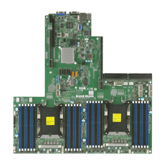
Introduction Congratulations on purchasing your computer motherboard from an acknowledged leader in the industry. Supermicro motherboards are designed with the utmost attention to detail to provide you with the highest standards in quality and performance. The X11DPU motherboard was designed to be used with a Supermicro-proprietary chassis as an integrated server platform. - Page 9 Chapter 1: Introduction Figure 1-1. X11DPU Motherboard Image Note: All graphics shown in this manual were based upon the latest PCB revision available at the time of publication of the manual. The motherboard you received may or may not look exactly the same as the graphics shown in this manual.
- Page 10 Super X11DPU User's Manual Figure 1-2. X11DPU Motherboard Layout (not drawn to scale) IPMI_LAN USB0/1 (3.0) COM1 JUIDB2 LED1 LEDM1 S-UM12 JSDCARD1 CTRL JTPM1 JRK1 JBT1 PSU2 PSU1 JSD2 JSD1 JHFI1 JNVI2C1 GPU PWR1 P1_NVMe0 P1_NVMe1 JHFI2 BIOS DESIGNED IN USA...
-
Page 11: Quick Reference
USB2 GPU PWR3 JNVI2C1 P2_NVMe1 JHFI2 BP PWR2 BP PWR4 P2_NVMe0 SXB3C BP PWR3 BP PWR1 BIOS GPU PWR2 DESIGNED IN USA X11DPU GPU PWR1 LICENSE REV:1.10 BAR CODE IPMI CODE GPU PWR4 T-SGPIO3 JNVI2C2 CPU1 CPU2 LEDPWR FAN4 FAN6... - Page 12 Super X11DPU User's Manual Quick Reference Table Jumper Description Default Setting JBT1 CMOS Clear Open (Normal) JPG1 VGA Enable/Disable Pins 1-2 (Enabled) JWD1 Watch Dog Pins 1-2 (Reset) Connector Description BP PWR1/2/3/4 8-pin Power Connectors 1/2/3/4 for Backplane Use Onboard Battery...
-
Page 13: Connector Description
Chapter 1: Introduction Connector Description T-SGPIO3 Serial_Link General Purpose I/O header for S-SATA4/5 USB0/1 Backplane Universal Serial Bus (USB) 3.0 Ports 0/1 USB3/4 Front Accessible USB 3.0 Header for USB 3/4 Connections USB2 USB 3.0 Type A Header VGA Port Description Status LED1... - Page 14 Note 1: The Intel® Xeon® Processor Scalable Family includes Intel® Xeon® Platinum 8100 processor, Intel® Xeon® Gold 6100/5100 processor, Intel® Xeon® Silver 4100 processor, and Intel® Xeon® Bronze 3100 processor. Note 2: For the latest CPU/memory updates, please refer to our website at http://www.supermicro.com/products/ motherboard.
- Page 15 • Power-on mode for AC power recovery • Intel® Intelligent Power Node Manager 4.0 (available when the Supermicro Power Manager [SPM] is installed and a special power supply is used. See the note on page 22.) • Management Engine (ME) System Health Monitoring •...
- Page 16 User's Guide available at http://www.supermicro.com/support/manuals/. Note 3: It is strongly recommended that you change BMC log-in information upon initial system power-on. The manufacture default username is ADMIN and the password is ADMIN. For proper BMC configuration, please refer to http://www.supermicro.com/ products/info/files/IPMI/Best_Practices_BMC_Security.pdf...
-
Page 17: System Block Diagram
Chapter 1: Introduction Figure 1-3. System Block Diagram DDR4 DDR3 NCSI AST2500 IPMI LAN RTL8211F RJ45 32MB BMC UART COM1 SPI FLASH LPC/eSPI Ultra IO Port A 0~7 32MB BIOS SPI FLASH Port B 0~7 Header USB2.0 [6,7] PE [5] LPC/eSPI Port B 8~15 SATA Gen3 [0..3]... -
Page 18: Processor And Chipset Overview
This motherboard is ideal for general purpose, cloud computing, and is optimized for server platforms used in data centers. With support of the new Intel® Omni-Path Fabric support, the X11DPU drastically increases system performance for a multitude of server applications. -
Page 19: System Health Monitoring
Chapter 1: Introduction 1.3 System Health Monitoring This section describes the health monitoring features of the X11DPU motherboard. The motherboard has an onboard Baseboard Management Controller (BMC) chip that supports system health monitoring. Once a voltage becomes unstable, a warning is given or an error message is sent to the screen. -
Page 20: Power Supply
Intelligent Power Node Manager (IPNM) ® Available when the Supermicro Power Manager (SPM) is installed, Intel's Intelligent Power Node Manager (IPNM) provides your system with real-time thermal control and power management for maximum energy efficiency. Although IPNM Specification Version 2.0/3.0 is supported by the BMC (Baseboard Management Controller), your system must also have IPNM-compatible Management Engine (ME) firmware installed to use this feature. -
Page 21: Management Engine (Me)
Chapter 1: Introduction Management Engine (ME) The Management Engine, which is an ARC controller embedded in the IOH (I/O Hub), provides Server Platform Services (SPS) to your system. The services provided by SPS are different from those provided by the ME on client platforms. -
Page 22: Chapter 2 Installation
Super X11DPU User's Manual Chapter 2 Installation 2.1 Static-Sensitive Devices Electrostatic Discharge (ESD) can damage electronic com ponents. To avoid damaging your motherboard and your system, it is important to handle it very carefully. The following measures are generally sufficient to protect your equipment from ESD. -
Page 23: Motherboard Installation
Philips Philips Screws Standoffs (14) Screwdriver (14) Only if Needed BIOS DESIGNED IN USA X11DPU LICENSE REV:1.10 BAR CODE IPMI CODE CPU1 CPU2 Location of Mounting Holes Note: 1) To avoid damaging the motherboard and its components, please do not use a force greater than 8 lb/inch on each mounting screw during motherboard installation. -
Page 24: Installing The Motherboard
Super X11DPU User's Manual Installing the Motherboard 1. Install the I/O shield into the back of the chassis. 2. Locate the mounting holes on the motherboard. See the previous page for the location. 3. Locate the matching mounting holes on the chassis. Align the mounting holes on the motherboard against the mounting holes on the chassis. -
Page 25: Processor And Heatsink Installation
CPU socket cap is in place and that none of the socket pins are bent; otherwise, contact your retailer immediately. • Refer to the Supermicro website for updates on CPU support. • Please follow the instructions given in the ESD Warning section on the first page of this chapter before handling, installing, or removing system components. -
Page 26: Overview Of The Processor Socket Assembly
Super X11DPU User's Manual Overview of the Processor Socket Assembly The processor socket assembly contains 1) the Intel 81xx/61xx/51xx/41xx/31xx processor, 2) the narrow processor clip, 3) the dust cover, and 4) the CPU socket. 1. The 81xx/61xx/51xx/41xx/31xx Processor 81xx/61xx/51xx/41xx/31xx (The Processor) 2. -
Page 27: Overview Of The Processor Heatsink Module (Phm)
Chapter 2: Installation Overview of the Processor Heatsink Module (PHM) The Processor Heatsink Module (PHM) contains 1) a heatsink, 2) a narrow processor clip, and 3) the 81xx/61xx/51xx/41xx/31xx processor. 1. Heatsink 2. Narrow processor clip 3. Intel Processor Processor Heatsink Module (PHM) (Bottom View for the non-F Model) (Bottom View for the F Model) -
Page 28: Attaching The Non-F Model Processor To The Narrow Processor Clip To Create The Processor Package Assembly
Super X11DPU User's Manual Attaching the Non-F Model Processor to the Narrow Processor Clip to Create the Processor Package Assembly To properly install the CPU into the narrow processor clip, please follow the steps below. 1. Locate pin 1 (notch A), which is the triangle located on the top of the narrow processor clip. -
Page 29: Attaching The F Model Processor To The Narrow Processor Clip To Create The Processor Package Assembly
Chapter 2: Installation Attaching the F Model Processor to the Narrow Processor Clip to Create the Processor Package Assembly To properly install the CPU into the narrow processor clip, please follow the steps below. 1. Locate pin 1 (notch A), which is the triangle located on the top of the narrow processor clip. -
Page 30: Processor Heatsink Module (Phm)
Super X11DPU User's Manual Attaching the Non-F Model Processor Package Assembly to the Heatsink to Form the Processor Heatsink Module (PHM) After you have made a processor package assembly by following the instructions on the previous page, please follow the steps below to mount the processor package assembly onto the heatsink to create the Processor Heatsink Module (PHM). -
Page 31: Attaching The F Model Processor Package Assembly To The Heatsink To Form The Processor Heatsink Module (Phm)
Chapter 2: Installation Attaching the F Model Processor Package Assembly to the Heatsink to Form the Processor Heatsink Module (PHM) After you have made a processor package assembly by following the instructions on the previous page, please follow the steps below to mount the processor package assembly onto the heatsink to create the Processor Heatsink Module (PHM). -
Page 32: Preparing The Cpu Socket For Installation
Super X11DPU User's Manual Preparing the CPU Socket for Installation This motherboard comes with the CPU socket pre-assembled in the factory. The CPU socket contains 1) a dust cover, 2) a socket bracket, 3) the CPU (P0) socket, and 4) a back plate. -
Page 33: Installing The Processor Heatsink Module (Phm)
Chapter 2: Installation Installing the Processor Heatsink Module (PHM) 1. Once you have assembled the processor heatsink module (PHM) by following the instructions listed on page 29 or page 30, you are ready to install the processor heatsink module (PHM) into the CPU socket on the motherboard. To install the PHM into the CPU socket, follow the instructions below. -
Page 34: Installing An Hfi Carrier Card For Host Fabric Interface (Hfi) Support As Needed (Available When The F Model Cpu Is Used)
Super X11DPU User's Manual Installing an HFI Carrier Card for Host Fabric Interface (HFI) Support as Needed (Available when the F Model CPU is Used) Note: Two host fabric interface carrier card headers (JHFI1/JHFI2) are located on the motherboard. Install an HFI card on an appropriate PCI-E slot of your choice and F model CPU(s) on CPU socket(s) to use this feature. -
Page 35: Removing The Processor Heatsink Module (Phm) From The Motherboard
Chapter 2: Installation Removing the Processor Heatsink Module (PHM) from the Motherboard Before removing the processor heatsink module (PHM), unplug power cord from the power outlet. 1. Using a T30 Torx-bit screwdriver, turn the screws on the PHM counterclockwise to loosen them from the socket, starting with screw marked #4 (in the sequence of 4, 3, 2, 2. -
Page 36: Memory Support And Installation
DIMM modules to prevent any damage. Memory Support The X11DPU supports up to 1536 GB of Load Reduced DIMM (LRDIMM), Registered DIMM (RDIMM), Non-Volatile DIMM (NV-DIMM) DDR4 (288-pin) ECC 2666/2400/2133/1866/1600/1333 MT/s modules in 24 slots memory slots. -
Page 37: Dimm Population Requirements For The 81Xx/61Xx/51Xx/41Xx/31Xx Series Processors
Chapter 2: Installation DIMM Population Requirements for the 81xx/61xx/51xx/41xx/31xx Series Processors For optimal memory performance, follow the tables below when populating memory modules. Key Parameters for DIMM Configurations Parameters Possible Values Number of Channels 1, 2, 3, 4, 5, or 6 Number of DIMMs per Channel 1DPC (1 DIMM Per Channel) or 2DPC (2 DIMMs Per Channel) DIMM Type... - Page 38 Super X11DPU User's Manual (DDR4 Only) Socket Level Population Requirements DDR4 Socket Level Minimum Population Requirements • There should be at least one DDR4 DIMM per socket. • If only one DIMM is populated in a channel, then populate it in the slot furthest away from CPU.
- Page 39 Chapter 2: Installation (DDR4 Only) 2SPC Memory Configuration with x4 DIMMs Total # of DDR Channel Number Adaptive Virtual DIMMs of Ranks Lock Step DIMM Popula- 1 x4 DIMM Must be installed on iMC0 DDR Channel 0 Y, only Bank VLS tion within an >1 Note: Uniformly...
-
Page 40: Dimm Installation
Super X11DPU User's Manual DIMM Installation 1. Insert the desired number of DIMMs into the memory slots, starting with P1-DIMM A1. For the system to work properly, please use memory modules of the same type and speed on the motherboard. -
Page 41: Rear I/O Ports
Chapter 2: Installation 2.5 Rear I/O Ports See Figure 2-2 below for the locations and descriptions of the various I/O ports on the rear of the motherboard. BIOS DESIGNED IN USA X11DPU LICENSE REV:1.10 BAR CODE IPMI CODE CPU1 CPU2 Figure 2-2. - Page 42 Super X11DPU User's Manual VGA Port One VGA port is located next to COM Port 1 on the I/O back panel. Use this connection for VGA display. Serial Port There is one COM port (COM1) on the I/O back panel on the motherboard. This COM port provides serial communication support.
- Page 43 GND_DRAIN Ground for Signal Return StdA_SSTX- SuperSpeed Transmitter StdA_SSTX+ Differential Pair 1. USB0 (3.0) 2. USB1 (3.0) 3. USB3/4 (USB 3.0) 4. Type A USB2 (USB 3.0) BIOS DESIGNED IN USA X11DPU LICENSE REV:1.10 IPMI CODE BAR CODE CPU1 CPU2...
- Page 44 Refer to the LED Indicator Section for LAN LED information. Note: For additional LAN connections, please install an appropriate Ultra riser card on Slot SXB3A/3B/3C. Please refer to the AOC list posted at http://www.supermicro.com/ support/resources/aoc/aoc_compatibility_ultra.cfm for more information.
-
Page 45: Front Control Panel
JF1 contains header pins for various buttons and indicators that are normally located on a control panel at the front of the chassis. These connectors are designed specifically for use with Supermicro chassis. See the figure below for the descriptions of the front control panel buttons and LED indicators. -
Page 46: Nmi Button
Super X11DPU User's Manual NMI Button The non-maskable interrupt button header is located on pins 19 and 20 of JF1. Refer to the table below for pin definitions. Power LED Pin Definitions (JF1) Pin# Definition Ground Power LED The Power LED connection is located on pins 15 and 16 of JF1. Refer to the table below for pin definitions. - Page 47 Chapter 2: Installation NIC1/NIC2 (LAN1/LAN2) The NIC (Network Interface Controller) LED connection for LAN port 1 is located on pin 12 of JF1, and LAN port 2 is on pin 10. Attach the NIC LED cables here to display network activity. Refer to the table below for pin definitions.
-
Page 48: Reset Button
Super X11DPU User's Manual Reset Button The Reset Button connection is located on pins 3 and 4 of JF1. Attach it to a hardware reset switch on the computer case to reset the system. Refer to the table below for pin definitions. -
Page 49: Connectors
6. BP PWR4 (Required) JSD2 JSD1 7. GPU PWR1 (Required) JHFI1 JNVI2C1 GPU PWR1 P1_NVMe0 P1_NVMe1 JHFI2 BIOS X11DPU DESIGNED IN USA 8. GPU PWR2 (Required) LICENSE REV:1.10 BAR CODE IPMI CODE 9. GPU PWR3 (Required) 10. GPU PWR4 (Required) CPU1... -
Page 50: Headers
Super X11DPU User's Manual Headers Fan Headers There are eight fan headers on the motherboard. These are 4-pin fan headers; pins 1-3 are backward compatible with traditional 3-pin fans. The onboard fan speeds are controlled by Thermal Management (via Hardware Monitoring) in the BIOS. When using Thermal Management setting, please use all 3-pin fans or all 4-pin fans. - Page 51 Note: For the HFI carrier card to function properly, please purchase the appropriate IFP cable from Supermicro. Please refer to Supermicro's website at www.supermicro. com for the part number of the IFP cable specified for your system. HFI Carrier Card Sideband Header...
- Page 52 Super X11DPU User's Manual T-SGPIO3 Header A Serial General Purpose Input/Output header (T-SGPIO3) is located on the motherboard. This header is used to communicate with the enclosure management chip on the backplane. See the table below for pin definitions. SGPIO Header...
- Page 53 1. TPM/Port 80 Header LED1 LEDM1 S-UM12 JSDCARD1 CTRL JTPM1 JRK1 JBT1 PSU2 PSU1 JSD2 JSD1 JHFI1 JNVI2C1 GPU PWR1 P1_NVMe0 P1_NVMe1 JHFI2 BIOS DESIGNED IN USA X11DPU LICENSE REV:1.10 BAR CODE IPMI CODE CPU1 CPU2 LEDPWR FAN3 FAN2 FAN1 FAN5...
-
Page 54: Chassis Intrusion
Super X11DPU User's Manual 4-pin BMC External I C Header A System Management Bus header for IPMI 2.0 is located at JIPMB1. Connect a cable to this header to use the IPMB I C connection on your system. See the table below for pin definitions. - Page 55 Chapter 2: Installation I-SATA 3.0 and S-SATA 3.0 Ports The X11DPU has eight I-SATA 3.0 ports (I-SATA0~3, I-SATA4~7) which are supported by the Intel® C621 chipset. In addition, it also has six S-SATA 3.0 ports (S-SATA0~3, S-SATA4/ S-SATA5) that are supported by the Intel® SCU. S-SATA4/5 can be used with Supermicro SuperDOMs which are yellow SATA DOM connectors with power pins built in, and do not require external power cables.
- Page 56 Super X11DPU User's Manual RAID Key Header A RAID_Key header is located at JRK1 on the motherboard. RAID key is used to support onboard NVMe connections. Please refer to the layout below for the location. RAID Key Header Pin Definitions...
- Page 57 OS image. Please refer to the layout below for the location. NVMe I C Header JNVI C1 and JNVI C2 are management headers for the Supermicro AOC NVMe PCI-E peripheral cards. Please connect the I C cable to the connector. IPMI_LAN USB0/1 (3.0) COM1 JUIDB2 1.
-
Page 58: Jumper Settings
Super X11DPU User's Manual 2.8 Jumper Settings How Jumpers Work To modify the operation of the motherboard, jumpers can be used to choose between optional settings. Jumpers create shorts between two pins to change the function of the connector. Pin 1 is identified with a square solder pad on the printed circuit board. See the diagram below for an example of jumping pins 1 and 2. - Page 59 1. VGA Enable/Disable LEDM1 2. CMOS Clear S-UM12 JSDCARD1 CTRL JTPM1 JRK1 JBT1 PSU1 PSU2 JSD2 JSD1 JHFI1 JNVI2C1 GPU PWR1 P1_NVMe0 P1_NVMe1 JHFI2 BIOS DESIGNED IN USA X11DPU LICENSE REV:1.10 BAR CODE IPMI CODE CPU1 CPU2 LEDPWR FAN3 FAN2 FAN1 FAN5...
- Page 60 Super X11DPU User's Manual Watch Dog JWD1 controls the Watch Dog function. Watch Dog is a monitor that can reboot the system when a software application hangs. Jumping pins 1-2 will cause Watch Dog to reset the system if an application hangs. Jumping pins 2-3 will generate a non-maskable interrupt signal for the application that hangs.
-
Page 61: Led Indicators
LED1 LEDM1 2. UID LED S-UM12 JSDCARD1 CTRL JTPM1 JRK1 JBT1 PSU1 PSU2 JSD2 JSD1 JHFI1 JNVI2C1 GPU PWR1 P1_NVMe0 P1_NVMe1 JHFI2 BIOS DESIGNED IN USA X11DPU LICENSE REV:1.10 BAR CODE IPMI CODE CPU1 CPU2 LEDPWR FAN3 FAN2 FAN1 FAN5... - Page 62 Super X11DPU User's Manual Onboard Power LED LEDPWR is an Onboard Power LED. When this LED is lit, it means that power is present on the motherboard. In suspend mode, this LED will blink on and off. Be sure to turn off the system and unplug the power cord(s) before removing or installing components.
- Page 63 7. LED_P2_A1-A2 JSD2 JSD1 JHFI1 JNVI2C1 GPU PWR1 P1_NVMe0 P1_NVMe1 8. LED_P2_B1-B2 6 5 4 JHFI2 BIOS DESIGNED IN USA X11DPU LICENSE REV:1.10 9. LED_P2_C1-C2 BAR CODE IPMI CODE 10. LED_P2_D1-D2 12 11 11. LED_P2_E1-E2 CPU1 12. LED_P2_F1-F2 CPU2 LEDPWR...
-
Page 64: Nvm Express Connections
Super X11DPU User's Manual 2.10 NVM Express Connections NVM Express Connections Four NVM Express ports are located on the motherboard. These NVM ports provide PCI-Exp. 3.0 x4 connections. P1_NVME0/1 are supported by CPU1. P2_NVME0/1 are supported by CPU2. The NVM Express ports provide high-speed low-latency connections directly from the CPU to NVMe Solid State (SSD) drives. -
Page 65: Chapter 3 Troubleshooting
Chapter 3: Troubleshooting Chapter 3 Troubleshooting 3.1 Troubleshooting Procedures Use the following procedures to troubleshoot your system. If you have followed all of the procedures below and still need assistance, refer to the ‘Technical Support Procedures’ and/ or ‘Returning Merchandise for Service’ section(s) in this chapter. Always disconnect the AC power cord before adding, changing or installing any non hot-swap hardware components. -
Page 66: System Boot Failure
Super X11DPU User's Manual No Video 1. If the power is on but you have no video, remove all the add-on cards and cables. 2. Use the speaker to determine if any beep codes exist. Refer to Appendix A for details on beep codes. -
Page 67: When The System Becomes Unstable
2. Memory support: Make sure that the memory modules are supported by testing the modules using memtest86 or a similar utility. Note: Refer to the product page on our website at http:\\www.supermicro.com memory and CPU support and updates. 3. HDD support: Make sure that all hard disk drives (HDDs) work properly. Replace the bad HDDs with good ones. - Page 68 Super X11DPU User's Manual 3. Using the minimum configuration for troubleshooting: Remove all unnecessary components (starting with add-on cards first), and use the minimum configuration (but with a CPU and a memory module installed) to identify the trouble areas. Refer to the steps listed in Section A above for proper troubleshooting procedures.
-
Page 69: Technical Support Procedures
Chapter 3: Troubleshooting 3.2 Technical Support Procedures Before contacting Technical Support, please take the following steps. Also, note that as a motherboard manufacturer, we do not sell directly to end-users, so it is best to first check with your distributor or reseller for troubleshooting services. They should know of any possible problem(s) with the specific system configuration that was sold to you. -
Page 70: Frequently Asked Questions
3.3 Frequently Asked Questions Question: What type of memory does my motherboard support? Answer: The X11DPU motherboard supports up to 64 GB of DDR4 2400 MHz ECC UDIMM memory. See Section 2.4 for details on installing memory. Question: How do I update my BIOS? Answer: It is recommended that you do not upgrade your BIOS if you are not experiencing any problems with your system. -
Page 71: Battery Removal And Installation
Chapter 3: Troubleshooting 3.4 Battery Removal and Installation Battery Removal To remove the onboard battery, follow the steps below: 1. Power off your system and unplug your power cable. 2. Locate the onboard battery as shown below. 3. Using a tool such as a pen or a small screwdriver, push the battery lock outwards to unlock it. -
Page 72: Returning Merchandise For Service
Super X11DPU User's Manual 3.5 Returning Merchandise for Service A receipt or copy of your invoice marked with the date of purchase is required before any warranty service is rendered. You can obtain service by calling your vendor for a Returned Merchandise Authorization (RMA) number. -
Page 73: Chapter 4 Bios
BIOS 4.1 Introduction This chapter describes the AMIBIOS™ Setup utility for the X11DPU motherboard. The BIOS is stored on a chip and can be easily upgraded using a flash program. Note: Due to periodic changes to the BIOS, some settings may have been added or deleted and might not yet be recorded in this manual. -
Page 74: Main Setup
Super X11DPU User's Manual 4.2 Main Setup When you first enter the AMI BIOS setup utility, you will enter the Main setup screen. You can always return to the Main setup screen by selecting the Main tab on the top of the screen. The Main BIOS setup screen is shown below. - Page 75 Chapter 4: BIOS Memory Information Total Memory This item displays the total size of memory available in the system.
-
Page 76: Advanced Setup Configurations
Super X11DPU User's Manual 4.3 Advanced Setup Configurations Use the arrow keys to select Boot Setup and press <Enter> to access the submenu items. Warning: Take caution when changing the Advanced settings. An incorrect value, a very high DRAM frequency, or an incorrect DRAM timing setting may make the system unstable. When this occurs, revert to the default to the manufacture default settings. - Page 77 Chapter 4: BIOS Wait For "F1" If Error Use this feature to force the system to wait until the 'F1' key is pressed if an error occurs. The options are Disabled and Enabled. INT19 (Interrupt 19) Trap Response Interrupt 19 is the software interrupt that handles the boot disk function. When this item is set to Immediate, the ROM BIOS of the host adaptors will "capture"...
-
Page 78: Cpu Configuration
Super X11DPU User's Manual Power Button Function This feature controls how the system shuts down when the power button is pressed. Select 4 Seconds Override for the user to power off the system after pressing and holding the power button for 4 seconds or longer. Select Instant Off to instantly power off the system as soon as the user presses the power button. - Page 79 Chapter 4: BIOS Execute Disable Bit (Available if supported by the OS & the CPU) Select Enable to enable the Execute-Disable Bit which will allow the processor to designate areas in the system memory where an application code can execute and where it cannot, thus preventing a worm or a virus from flooding illegal codes to overwhelm the processor or damage the system during an attack.
-
Page 80: Advanced Power Management Configuration
Super X11DPU User's Manual Extended APIC Select Enable to use the extended APIC (Advanced Programmable Interrupt Control) support to enhance power management. The options are Disable and Enable. AES-NI Select Enable to use the Intel® Advanced Encryption Standard (AES) New Instructions (NI) to ensure data security. -
Page 81: Chipset Configuration
Chapter 4: BIOS CPU C6 report Select Enable to allow the BIOS to report the CPU C6 State (ACPI C3) to the operating system. During the CPU C6 State, the power to all cache is turned off. The options are Disable, Enable, and Auto. -
Page 82: Memory Configuration
Super X11DPU User's Manual • UPI Global MMIO Low Base/Limit • UPI Global MMIO High Base/Limit • UPI Pci-e Configuration Base/Size Degrade Precedence Select Topology Precedence to degrade features if system options are in conflict. Select Feature Precedence to degrade topology if system options are in conflict. The options are Topology Precedence and Feature Precedence. - Page 83 Chapter 4: BIOS Data Scrambling for DDR4 Use this feature to enable data scrambling for DDR4. The options are Auto, Disable, and Enable. Enable ADR Select Enable for ADR (Automatic Diagnostic Repository) support to enhance memory performance. The options are Disable and Enable. Refresh Options Use this item to select the self refresh mode.
-
Page 84: Iio Configuration
Super X11DPU User's Manual Multi Rank Sparing Use this feature to set the multiple rank sparing number. The default setting and the maximum is two ranks per channel. The options are One Rank and Two Rank. Correctable Error Threshold Use this item to enter the threshold value for correctable memory errors. The default setting is 10. - Page 85 Chapter 4: BIOS CPU1 Configuration IOU0 (IIO PCIe Br1) This item configures the PCI-E port Bifuraction setting for a PCI-E port specified by the user. The options are x4x4x4x4, x4x4x8, x8x4x4, x8x8, x16, and Auto. IOU1 (IIO PCIe Br2) This item configures the PCI-E port Bifuraction setting for a PCI-E port specified by the user.
- Page 86 Super X11DPU User's Manual P1_NVMe1 Link Speed Use this feature to select the link speed for the PCIe port. The options are Auto, Gen 1 (2.5 GT/s), Gen 2 (5 GT/s), and Gen 3 (8 GT/s). PCI-E Port Link Status...
- Page 87 Chapter 4: BIOS PCI-E Port Link Status PCI-E Port Link Max PCI-E Port Link Speed PCI-E Port Max Payload Size Select Auto for the system BIOS to automatically set the maximum payload value for a PCI-E device to enhance system performance. The options are 128B, 256B, and Auto.
- Page 88 Super X11DPU User's Manual PCI-E Port Max Payload Size Select Auto for the system BIOS to automatically set the maximum payload value for a PCI-E device to enhance system performance. The options are 128B, 256B, and Auto. AOC-URN6-i2XT NVME6 (Available when the device is detected by...
- Page 89 Chapter 4: BIOS MCP1 (IIO PCIe Br5) This item configures the PCI-E port Bifuraction setting for a PCI-E port specified by the user. The options are x16 and Auto. RSC-UMR-8 SLOT1 Link Speed This feature allows the user to select PCI-E support for the device installed in the system.
- Page 90 Super X11DPU User's Manual PCI-E Port Link Status PCI-E Port Link Max PCI-E Port Link Speed PCI-E Port Max Payload Size Select Auto for the system BIOS to automatically set the maximum payload value for a PCI-E device to enhance system performance. The options are 128B, 256B, and Auto.
- Page 91 Chapter 4: BIOS Select Enable to use the Non-Isoch VT_D engine ATS support. The options are En- able and Disable. Posted Interrupt Use this feature to enable VT_D posted interrupt. The options are Enable and Disable. Coherency Support (Non-Isoch) Select Enable for the Non-Iscoh VT-d engine to pass through DMA (Direct Memory Access) to enhance system performance.
- Page 92 Super X11DPU User's Manual *If the item above "Intel® VMD for Volume Management Device" is set to Enable, the following items will be displayed: AOC-URN6-i2XT NVME2 VMD (Available when the device is detected by the system) Select Enable to use the Intel® Volume Management Device Technology for this device.
- Page 93 Chapter 4: BIOS Intel® VMD for Volume Management Device on CPU2 VMD Config for PStack0 Intel® VMD for Volume Management Device Select Enable to use the Intel® Volume Management Device Technology for this stack. The options are Disable and Enable. *If the item above "Intel®...
-
Page 94: South Bridge
Super X11DPU User's Manual *If the item above "Intel® VMD for Volume Management Device" is set to Enable, the following items will be displayed: Hot Plug Capable (Available when the device is detected by the system) Use this feature to enable the hot plug support for PCIe root ports 3A~3D. The op- tions are Disable and Enable. -
Page 95: Pch Sata Configuration
Chapter 4: BIOS • ME Firmware Status #1 • ME Firmware Status #2 • Current State • Error Code PCH SATA Configuration SATA Controller This item enables or disables the onboard SATA controller supported by the Intel® PCH chip The options are Disable and Enable. Configure SATA as Select AHCI to configure a SATA drive specified by the user as an AHCI drive. - Page 96 Super X11DPU User's Manual Spin Up Device (SATA Port 0~ Port 7) On an edge detect from 0 to 1, set this item to allow the PCH to initialize the device. The options are Disable and Enable. SATA Device Type (SATA Port 0~ Port 7) Use this item to specify if the SATA port specified by the user should be connected to a Solid State drive or a Hard Disk Drive.
- Page 97 Chapter 4: BIOS PCH sSATA Configuration sSATA Controller This item enables or disables the onboard SATA controller supported by the Intel® PCH chip The options are Enable and Disable. Configure sSATA as Select AHCI to configure a SATA drive specified by the user as an AHCI drive. Select RAID to configure a SATA drive specified by the user as a RAID drive.
- Page 98 Super X11DPU User's Manual *If the item above "Configure SATA as" is set to RAID, the following items will be displayed: sSATA RSTe Boot Info Select Enable to provide the full int13h support for SATA controller attached devices. The options are Disable and Enable.
- Page 99 Chapter 4: BIOS SR-IOV Support Use this feature to enable or disable Single Root IO Virtualization support. The options are Disabled and Enabled. MMIO High Base Use this item to select the base memory size according to memory-address mapping for the IO hub.
-
Page 100: Network Stack Configuration
Super X11DPU User's Manual Select an option to enable Option ROM support to boot the computer using a device specified by the user. The options are Legacy and EFI. Onboard LAN1 Option ROM Onboard LAN2 Option ROM Use the above four items to select the type of device installed in a LAN port specified by the user for system boot. -
Page 101: Super Io Configuration
Chapter 4: BIOS Media detect count Use this option to specify the number of times media will be checked. Press "+" or "-" on your keyboard to change the value. The default setting is 1. Super IO Configuration Super IO Configuration The following Super IO information will be displayed: •... -
Page 102: Serial Port Console Redirection
Super X11DPU User's Manual Change Settings This feature specifies the base I/O port address and the Interrupt Request address of a serial port specified by the user. Select Auto to allow the BIOS to automatically assign the base I/O and IRQ address. The options are Auto, (IO=2F8h; IRQ=3;), (IO=3F8h; IRQ=3, 4, 5, 6, 7, 9, 10, 11, 12;), (IO=2F8h;... - Page 103 Chapter 4: BIOS Data Bits Use this feature to set the data transmission size for Console Redirection. The options are 7 and 8. Parity A parity bit can be sent along with regular data bits to detect data transmission errors. Select Even if the parity bit is set to 0, and the number of 1's in data bits is even.
- Page 104 Super X11DPU User's Manual Redirection After BIOS POST Use this feature to enable or disable legacy console redirection after BIOS POST. When this feature is set to BootLoader, legacy console redirection is disabled before booting the OS. When this feature is set to Always Enable, legacy console redirection remains enabled when booting the OS.
- Page 105 Chapter 4: BIOS the parity bit is set to 0, and the number of 1's in data bits is odd. Select None if you do not want to send a parity bit with your data bits in transmission. Select Mark to add a mark as a parity bit to be sent along with the data bits.
- Page 106 Super X11DPU User's Manual Legacy Console Redirection Legacy Serial Redirection Port Use the feature to select the COM port to display redirection of Legacy OS and Legacy OPROM messages. The options are COM1 and SOL. Serial Port for Out-of-Band Management/Windows Emergency Management Services...
-
Page 107: Acpi Settings
Chapter 4: BIOS is full. Send a "Start" signal to start data-sending when the receiving buffer is empty. The options are None, Hardware RTS/CTS, and Software Xon/Xoff. The settings below are displayed: Data Bits, Parity, Stop Bits ACPI Settings NUMA (Available when the OS supports this feature) Select Enabled to enable Non-Uniform Memory Access support to enhance system performance. -
Page 108: Iscsi Configuration
Super X11DPU User's Manual SHA-1 PCR Bank Use this item to disable or enable the SHA-1 Platform Configuration Register (PCR) bank for the installed TPM device. The options are Disabled and Enabled. SHA256 PCR Bank Use this item to disable or enable the SHA256 Platform Configuration Register (PCR) bank for the installed TPM device. - Page 109 Chapter 4: BIOS Add an Attempt Delete Attempts Change Attempt order Intel® Virtual RAID on CPU This submenu displays the information of the Intel® VMD controllers as detected by the BIOS.
-
Page 110: Event Logs
Super X11DPU User's Manual 4.4 Event Logs Use this feature to configure the Event Log settings. Change SMBIOS Event Log Settings Enabling/Disabling Options SMBIOS Event Log Change this item to enable or disable all features of the SMBIOS (System Management BIOS) Event Logging during system boot. -
Page 111: View Smbios Event Log
Chapter 4: BIOS SMBIOS Event Log Standard Settings Log System Boot Event This option toggles the System Boot Event logging to enabled or disabled. The options are Enabled and Disabled. MECI The Multiple Event Count Increment (MECI) counter counts the number of occurrences that a duplicate event must happen before the MECI counter is incremented. -
Page 112: Ipmi
Super X11DPU User's Manual 4.5 IPMI Use this feature to configure Intelligent Platform Management Interface (IPMI) settings. BMC Firmware Revision This item indicates the IPMI firmware revision used in your system. IPMI STATUS (Baseboard Management Controller) This item indicates the status of the IPMI firmware installed in your system. -
Page 113: Bmc Network Configuration
Chapter 4: BIOS When SEL is Full This feature allows the user to decide what the BIOS should do when the system event log is full. Select Erase Immediately to erase all events in the log when the system event log is full. - Page 114 Super X11DPU User's Manual Station MAC Address This item displays the Station MAC address for this computer. Mac addresses are 6 two-digit hexadecimal numbers. Gateway IP Address This item displays the Gateway IP address for this computer. This should be in decimal and in dotted quad form (i.e., 172.31.0.1).
-
Page 115: Security
Chapter 4: BIOS 4.6 Security This menu allows the user to configure the following security settings for the system. Administrator Password Press Enter to set the user password which is required to enter the BIOS setup utility. The length of the password should be from 3 characters to 20 characters long. User Password Press Enter to set the user password which is required to enter the BIOS setup utility. -
Page 116: Key Management
Super X11DPU User's Manual Secure Boot Use this item to enable secure boot. The options are Disabled and Enabled. Secure Boot Mode Use this item to select the secure boot mode. The options are Standard and Custom. CSM Support Select Enabled to support the EFI Compatibility Support Module (CSM), which provides compatibility support for traditional legacy BIOS for system boot. - Page 117 Chapter 4: BIOS Key Exchange Keys (KEK) Select Set New to load the KEK from the manufacturer's defaults. Select Append to add the KEK from the manufacturer's defaults list to the existing KEK. The default setting is Set New. Authorized Signatures ...
-
Page 118: Boot
Super X11DPU User's Manual 4.7 Boot Use this feature to configure Boot Settings: Boot mode select Use this item to select the type of device that the system is going to boot from. The options are LEGACY, UEFI, and DUAL. The default setting is DUAL. -
Page 119: Delete Boot Option
Chapter 4: BIOS • Legacy/UEFI/Dual Boot Order #6 • Legacy/UEFI/Dual Boot Order #7 • Legacy/UEFI/Dual Boot Order #8 • UEFI/Dual Boot Order #9 • Dual Boot Order #10 • Dual Boot Order #11 • Dual Boot Order #12 • Dual Boot Order #13 •... -
Page 120: Save & Exit
Super X11DPU User's Manual 4.8 Save & Exit Select the Save & Exit tab from the BIOS setup screen to configure the settings below. Save Options Discard Changes and Exit Select this option to quit the BIOS Setup without making any permanent changes to the system configuration, and reboot the computer. - Page 121 Chapter 4: BIOS Default Options Restore Defaults To set this feature, select Restore Optimized Defaults from the Save & Exit menu and press <Enter>. These are factory settings designed for maximum system stability, but not for maximum performance. Save As User Defaults To set this feature, select Save as User Defaults from the Exit menu and press <Enter>.
-
Page 122: Appendix A Bios Codes
Super X11DPU User's Manual Appendix A BIOS Codes A.1 BIOS Error POST (Beep) Codes During the POST (Power-On Self-Test) routines, which are performed each time the system is powered on, errors may occur. Non-fatal errors are those which, in most cases, allow the system to continue the bootup process. - Page 123 When BIOS performs the Power On Self Test, it writes checkpoint codes to I/O port 0080h. If the computer cannot complete the boot process, a diagnostic card can be attached to the computer to read I/O port 0080h (Supermicro p/n AOC-LPC80-20). For information on AMI updates, please refer to http://www.ami.com/products/.
-
Page 124: Appendix B Software Installation
Appendix B Software Installation B.1 Installing Software Programs The Supermicro FTP site contains drivers and utilities for your system at ftp://ftp.supermicro. com. Some of these must be installed, such as the chipset driver. After accessing the FTP site, go into the CDR_Images directory and locate the ISO file for your motherboard. -
Page 125: Superdoctor ® 5
SATA settings back to your original settings. B.2 SuperDoctor ® The Supermicro SuperDoctor 5 is a hardware monitoring program that functions in a command-line or web-based interface in Windows and Linux operating systems. The program monitors system health information such as CPU temperature, system voltages, system power consumption, fan speed, and provides alerts via email or Simple Network Management Protocol (SNMP). -
Page 126: Appendix C Uefi Bios Recovery
Warning: Do not upgrade the BIOS unless your system has a BIOS-related issue. Flashing the wrong BIOS can cause irreparable damage to the system. In no event shall Supermicro be liable for direct, indirect, special, incidental, or consequential damages arising from a BIOS update. - Page 127 USB device or a writable CD/DVD. Notes: 1. If you cannot locate the "Super.ROM" file in your drive disk, visit our website www.supermicro.com to download the BIOS package. Extract the BIOS binary im- age into a USB flash device and rename it "Super.ROM" for the BIOS recovery use. 2.
- Page 128 Super X11DPU User Manual 3. After locating the healthy BIOS binary image, the system will enter the BIOS Recovery menu as shown below. Note: At this point, you may decide if you want to start the BIOS recovery. If you decide to proceed with BIOS recovery, follow the procedures below.
- Page 129 Appendix C: UEFI BIOS Recovery 5. After the BIOS recovery process is complete, press any key to reboot the system. 6. Using a different system, extract the BIOS package into a USB flash drive. 7. Press <Del> continuously during system boot to enter the BIOS Setup utility. From the top of the tool bar, select Boot to enter the submenu.
- Page 130 Super X11DPU User Manual 8. When the UEFI Shell prompt appears, type fs# to change the device directory path. Go to the directory that contains the BIOS package you extracted earlier from Step 6. Enter flash.nsh BIOSname.### at the prompt to start the BIOS update process.
-
Page 131: Appendix D Standardized Warning Statements
The following statements are industry standard warnings, provided to warn the user of situations which have the potential for bodily injury. Should you have questions or experience difficulty, contact Supermicro's Technical Support department for assistance. Only certified technicians should attempt to install or configure components. - Page 132 Super X11DPU User's Manual Attention Danger d'explosion si la pile n'est pas remplacée correctement. Ne la remplacer que par une pile de type semblable ou équivalent, recommandée par le fabricant. Jeter les piles usagées conformément aux instructions du fabricant. ¡Advertencia! Existe peligro de explosión si la batería se reemplaza de manera incorrecta.
-
Page 133: Product Disposal
Appendix D: Warning Statements Product Disposal Warning! Ultimate disposal of this product should be handled according to all national laws and regulations. 製品の廃棄 この製品を廃棄処分する場合、 国の関係する全ての法律 ・ 条例に従い処理する必要があります。 警告 本产品的废弃处理应根据所有国家的法律和规章进行。 警告 本產品的廢棄處理應根據所有國家的法律和規章進行。 Warnung Die Entsorgung dieses Produkts sollte gemäß allen Bestimmungen und Gesetzen des Landes erfolgen.