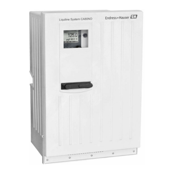
Endress+Hauser Liquiline System CA80NO Brief Operating Instructions
Colorimetric analyzer for nitrite
Hide thumbs
Also See for Liquiline System CA80NO:
- Brief operating instructions (44 pages) ,
- Operating instructions manual (172 pages)
Table of Contents
Advertisement
Quick Links
KA01222C/07/EN/02.16
71313629
Valid as of version
01.06.00
Products
Brief Operating Instructions
Liquiline System CA80NO
Colorimetric analyzer for nitrite
These Instructions are Brief Operating Instructions; they are
not a substitute for the Operating Instructions pertaining to
the device.
Detailed information on the device can be found in the
Operating Instructions and in the other documentation
available at:
• www.endress.com/device-viewer
• Smart phone/tablet: Endress+Hauser Operations App
Solutions
Services
Advertisement
Table of Contents

Related Manuals for Endress+Hauser Liquiline System CA80NO


Summary of Contents for Endress+Hauser Liquiline System CA80NO
- Page 1 These Instructions are Brief Operating Instructions; they are not a substitute for the Operating Instructions pertaining to the device. Detailed information on the device can be found in the Operating Instructions and in the other documentation available at: • www.endress.com/device-viewer • Smart phone/tablet: Endress+Hauser Operations App...
- Page 2 Liquiline System CA80NO Order code 00X00-XXXX0XX0XXX Ser. No.: X000X000000 TAG No.: XXX000 Serial number www.endress.com/deviceviewer Endress+Hauser Operations App A0023555 Endress+Hauser...
-
Page 3: Table Of Contents
Liquiline System CA80NO Table of contents Table of contents Document information ............4 Warnings . -
Page 4: Document Information
Document information Liquiline System CA80NO Document information Warnings Structure of information Meaning This symbol alerts you to a dangerous situation. DANGER Failure to avoid the dangerous situation will result in a fatal or serious injury. Causes (/consequences) Consequences of non-compliance (if applicable) ‣... -
Page 5: Symbols At The Device
Warning: Crush hazard Documentation The following instructions complement these Brief Operating Instructions and are available on the product pages on the internet: • Operating Instructions for Liquiline System CA80NO – Device description – Commissioning – Operation – Software description (excluding sensor menus; these are described in a separate manual - see below) –... -
Page 6: Basic Safety Instructions
Designated use Liquiline System CA80NO is a wet-chemical analyzer for the almost continuous determination of the concentration of nitrite in liquid media. The analyzer is designed for use in the following applications: •... -
Page 7: Product Safety
Liquiline System CA80NO Basic safety instructions If faults cannot be rectified: Take the products out of operation and safeguard them to ensure that they are not operated inadvertently. Keep this door closed when not carrying out service and maintenance work. -
Page 8: Incoming Acceptance And Product Identification
Incoming acceptance and product identification Liquiline System CA80NO Incoming acceptance and product identification Incoming acceptance Verify that the packaging is undamaged. Notify your supplier of any damage to the packaging. Keep the damaged packaging until the matter has been settled. -
Page 9: Scope Of Delivery
Liquiline System CA80NO Incoming acceptance and product identification 3.2.2 Product identification Product page www.endress.com/ca80no Interpreting the order code The order code and serial number of your product can be found in the following locations: • On the nameplate • In the delivery papers Obtaining information on the product Go to the product page for your product on the Internet. -
Page 10: Installation
Installation Liquiline System CA80NO Installation CAUTION Incorrect transportation or installation can cause injury and damage the device ‣ Always use a lifting truck or a fork-lift to transport the analyzer. Two people are needed for the installation. ‣ Lift the device by the recessed grips. - Page 11 Liquiline System CA80NO Installation 417 (16.42) 530 (20.87) A0028819 2 Liquiline System CA80 open version with cooling module, dimensions in mm (inch) Endress+Hauser...
- Page 12 Installation Liquiline System CA80NO 654 (25.74) A0028821 3 Liquiline System CA80 with base, dimensions in mm (inch) 4.1.3 Installation site Note the following when erecting the device: • Make sure that the wall has sufficient load-bearing capacity and is fully perpendicular.
-
Page 13: Mounting The Analyzer On A Wall
Liquiline System CA80NO Installation • Make sure that the fluid can drain freely without any siphoning effects. • Make sure air can circulate freely on the front of the housing. • Make sure that analyzers which are delivered as open analyzers (i.e. analyzers without a door) are only set up in closed areas or are installed in a protective cabinet or similar facility. - Page 14 Installation Liquiline System CA80NO Ø 11 (0.43) Ø 10.7 (0.42) 120 (4.72) A0028810 7 Securing the holder unit on the housing 6 Holder unit dimensions. Engineering unit mm (inch) Endress+Hauser...
- Page 15 Liquiline System CA80NO Installation A0028812 8 Hooking into the wall holder unit Hook the analyzer into the wall holder unit. Secure the two top parts of the wall holder unit with the screw supplied. Endress+Hauser...
-
Page 16: Mounting The Analyzer On A Base (Analyzer Stand Order Version)
Installation Liquiline System CA80NO Mounting the analyzer on a base (analyzer stand order version) 624 (24.57) 530 (20.87) A0028809 9 Foundation plan Fasteners (4 x M10) Dimensions of Liquiline System CA80 Endress+Hauser... -
Page 17: Post-Installation Check
Liquiline System CA80NO Electrical connection A0028817 10 Securing the base Screw the base to the ground. Have two people lift the analyzer and place it on the base. Use the recessed grips. Screw the base to the analyzer using the 6 screws supplied. -
Page 18: Connecting The Analyzer
Electrical connection Liquiline System CA80NO Connecting the analyzer NOTICE The device does not have a power switch ‣ You must install the device near (distance < 3 m (10 ft)) an easily accessible and fused plug socket so that it can be disconnected from the power supply. - Page 19 Liquiline System CA80NO Electrical connection Using a Phillips head screwdriver, release the six screws on the electronics compartment cover (4) and fold out the cover towards the front. A0028912 Screws of carrier board Screws of electronics compartment cover Endress+Hauser...
- Page 20 Electrical connection Liquiline System CA80NO Route the cables on the rear panel of the device so that they are properly protected. Cable glands are available for the cable entry. A0028913 Cable glands In the case of order versions with G' and NPT cable glands, the pre-mounted cable glands with an M‐thread must be replaced by the G' or NPT glands enclosed.
-
Page 21: Connecting Sample Preparation
Liquiline System CA80NO Electrical connection Guide the 24V connecting cable from below through the cable gland on the inner rear panel of the device and feed it upwards into the electronics compartment. Establish the connection as per → 11, 21 A0028910 ... - Page 22 Electrical connection Liquiline System CA80NO Guide the cable through the cable gland. In the case of order versions with G' and NPT cable glands, the pre-mounted cable glands with an M‐thread must be replaced by the G' or NPT glands enclosed.
- Page 23 Liquiline System CA80NO Electrical connection Cable sample (does not necessarily correspond to the genuine cable supplied) 14 Inserting the cable Shielding clamp for Memosens supply and power supply Cable clamp for hose heating 13 Terminated cable 15...
-
Page 24: Connecting The Sensors And Additional Modules
Electrical connection Liquiline System CA80NO Route the cable in the housing in such a way that the exposed cable shield fits into one of the cable clamps and the cable cores can be easily routed as far as the plug-in terminals. - Page 25 Liquiline System CA80NO Electrical connection BASE-E A0028935 17 Connection compartment in the controller housing E basic module Analyzer interface Dummy cover Module cover E basic module 24 VDC Power A0016535 18 E basic module Indicator LEDs Slot for display cable...
- Page 26 Electrical connection Liquiline System CA80NO Alarm relay connection Connections for 2 Memosens sensors (optional) Power supply for digital fixed cable sensors Current outputs with Memosens protocol SD card slot Internal device connection. Do not disconnect the plug! 85 86 24VDC...
- Page 27 Liquiline System CA80NO Electrical connection Establish the connection as per → 20, 26 Ground the outer shield of the cable via the metal gland under the E basic module. A0028930 21 Terminal strip 5.3.3 Connecting additional inputs, outputs or relays...
- Page 28 Electrical connection Liquiline System CA80NO Digital inputs and outputs DIO module – – – – – – 22 Module 23 Wiring diagram Current inputs Module 2AI – – 24 Module 25 Wiring diagram Endress+Hauser...
- Page 29 Liquiline System CA80NO Electrical connection Current outputs – – – – – – 26 Module 27 Wiring 28 Module 29 Wiring diagram diagram Relay Module 2R Module 4R 33 Wiring 30 Module 31 Wiring ...
- Page 30 Electrical connection Liquiline System CA80NO 5.3.4 Connecting digital communication Module 485 128/SW Service DGND 35 Wiring 34 Module diagram LEDs on front of module Description Color Description RJ45 LNK/ACT • Off = Connection is not active • On = Connection is active •...
- Page 31 Liquiline System CA80NO Electrical connection DIP switches on front of module Factory setting Assignment 1-128 Bus address (→ "Commissioning/communication") Write protection: "ON" = configuration not possible via the bus, only via local operation Service If the switch is set to "ON" , the user settings for Ethernet addressing are saved and connection settings programmed into the device at the factory are activated: IP address=192.168.1.212, Subnet mask=255.255.255.0, Gateway=0.0.0.0, DHCP=Off.
-
Page 32: Hardware Settings
Electrical connection Liquiline System CA80NO DIP switches on front of module Factory setting Assignment 1-128 Bus address (→ "Commissioning/communication") Write protection: "ON" = configuration not possible via the bus, only via local operation Service If the switch is set to "ON" , the user settings for Ethernet addressing are saved and connection settings programmed into the device at the factory are activated: IP address=192.168.1.212, Subnet mask=255.255.255.0, Gateway=0.0.0.0, DHCP=Off. -
Page 33: Ensuring The Degree Of Protection
Liquiline System CA80NO Electrical connection Here, leave the DIP switches on the module board in the "OFF" position (factory setting). ‣ Connect the resistor to terminals 81 and 82 on the front of module 485 for 5‐V power supply. The external terminating resistor is used. -
Page 34: Post-Connection Check
Electrical connection Liquiline System CA80NO Individual types of protection permitted for this product (impermeability (IP), electrical safety, EMC interference immunity, Ex protection) can no longer be guaranteed if, for example: • Covers are left off. • Different power units to the ones supplied are used. -
Page 35: Operation Options
Liquiline System CA80NO Operation options Operation options Overview 6.1.1 Display and operating elements Display (with red display background in alarm condition) Navigator (jog/shuttle and press/hold Analyzer_CA80 09:11:05 01.03.2016 function) Soft keys (function depends on menu) SP1: NO2-N mg/l MODE DIAG HOLD... -
Page 36: Access To The Operating Menu Via The Local Display
Operation options Liquiline System CA80NO Access to the operating menu via the local display 6.2.1 Operating concept MODE DIAG MENU MODE DIAG HOLD Turning the navigator: moving the cursor in the menu Pressing the soft key: selecting the menu directly... -
Page 37: Configuration Options
Liquiline System CA80NO Operation options 6.2.2 Locking or unlocking operating keys Locking operating keys Press the navigator for longer than 2 s. A context menu for locking the operating keys is displayed. You have the choice of locking the keys with or without password protection. "With password"... - Page 38 Operation options Liquiline System CA80NO 6.3.3 Numerical values • You are changing a variable. • The maximum and minimum values for this variable are shown on the display. • Set a value within this range. • Example: Menu/Operation/Display/Contrast Menu/...ration/Display/Contrast 6.3.4 Actions •...
- Page 39 Liquiline System CA80NO Operation options 6.3.5 Free text • You are assigning an individual designation. • Enter a text. You can use the characters in the editor for this purpose (upper-case and lower-case letters, numbers and special characters). • Using the soft keys, you can: –...
-
Page 40: Commissioning
Commissioning Liquiline System CA80NO 6.3.6 Tables • Tables are needed to map mathematical functions . • You edit a table by navigating through rows and columns with the navigator and changing the values of the cells. • You only edit the numerical values. The controller automatically takes care of the engineering units. - Page 41 Liquiline System CA80NO Commissioning If present, connect the communication cable and hose heater of the sample preparation system to the analyzer. Ensure that only sample that has a low solids content is supplied, as otherwise there is a risk of blockage. The customer must guarantee a constant and sufficient volume of sample.
- Page 42 Commissioning Liquiline System CA80NO Hose connection diagram A0028832 45 Liquiline System CA80NO, single-channel device optional cooling A0028833 46 Liquiline System CA80NO, two-channel device and self-priming Endress+Hauser...
-
Page 43: Function Check
Liquiline System CA80NO Commissioning Cleaner Photometer cuvette Standard 1 Sample Reagent RK 2, 3, 7 Dispensers Procedure Procedure Photometer/measuring cell Sample collecting vessel Function check WARNING Incorrect connection, incorrect supply voltage Safety risks for staff and device malfunctions ‣ Check that all connections have been established correctly in accordance with the wiring diagram. -
Page 44: Switching On The Measuring Device
Commissioning Liquiline System CA80NO Switching ON the measuring device ‣ Switch on the supply voltage. Wait for initialization. Setting the operating language Configure language ‣ Press the soft key MENU. Set your language in the top menu item. The device can now be operated in your chosen language. - Page 48 *71313629* 71313629 www.addresses.endress.com...