
Summary of Contents for Pulse Xyleject
- Page 1 8210 Marshall Drive --- Lenexa, KS 66214 --- 913-599-1590 Xyleject Operator’s Manual P/N 402175-01 4/6/21 XYL21-004...
- Page 2 Pulse must verify the warranty claim. (Actual testing may be necessary for verification of the system or component). o The end user customer must return to Pulse the system or component the end user customer claims to be defective, and Pulse must confirm the claimed defect.
- Page 3 Removing a Bent Needle ------------------------------------------ Section 12 Cleaning the Injection Device -------------------------------------- Section 13 Changing Medicine Piston O-Ring ------------------------------- Section 14 Troubleshooting ----------------------------------------------------- Section 15 Re-Filling CO2 Tanks ------------------------------------------------- Section 16 Copyright 2020 Pulse Biotech, LLC, and its affiliates. All rights reserved.
- Page 4 IMPORTANT! Read all instructions and warnings before using this product. Misuse may cause serious injury. This manual is intended to provide instructions for the use and care of the Pulse Xyleject injection device, but it does not replace effective hands-on training by an experienced user / trainer. Complete familiarity with this product is required prior to field injection.
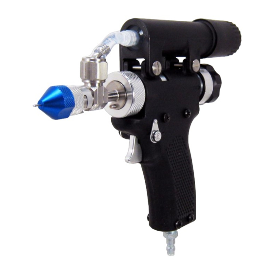
- Page 5 Protective gloves, eye protection, long sleeves, pants, socks, and shoes are required. SECTION 2 – PRODUCT SPECIFICATIONS The Pulse Xyleject injection device is designed specifically to provide injections into the xylem of grapevines. The device is designed to propel a pre-set dose of liquid into the grapevine, using controlled pneumatic pressure.
- Page 6 IMAGE NAME Conical Needles (18-gauge & 20-gauge) Needle Retention Nut Base (with O-Ring) 3mm 20-gauge Needle Retention Nut 4mm 18-gauge Needle Retention Nut 6mm 18-gauge Needle Retention Nut Flexible Compartment Connector Suction Tube Holding Compartment Barrel Barrel Cap Needle O-Ring Kit Medicine Piston O-Ring Kit...
- Page 7 IMAGE NAME Compartment Plunger Pneumatic Hose Vest Device Holster Lubricant CO2 Small Tank Adapter (88 Grams) Pressure Regulator Portable CO2 Tank, 24-Ounce Scale CO2 Filling Station...
- Page 8 SECTION 4 – OPERATING THE SAFETY LEVER The Xyleject injection device is equipped with a dual safety lever system that allows the operator to engage or dis-engage either of the safety levers with either the right or left hand. The safety levers are located on each side of the device’s handle grip such that the operator can reach the safety lever from either side of the device.
- Page 9 20-Gauge Conical Needle Needle Retention Nut Selection: The Needle Retention Nut is attached to the Needle Retention Nut Base and, together, these components secure the Conical Needle on the injection device. The Xyleject device comes with a set of Needle Retention Nuts.
- Page 10 SECTION 6 – NEEDLE INSTALLATION Needle Installation: To install the needle: Place the desired Needle Retention Nut on to the Needle Retention Nut Base by two threads counter clockwise as shown below. This keeps the Needle covered during the installation. Place the O-Ring for the Conical Needle on the front portion of the injection device as shown.
- Page 11 SECTION 7 – FILLING AND INSTALLING THE HOLDING COMPARTMENT During the injection process, the injectate is held in the Holding Compartment. (See the XylPhi-PD Product Insert for information about proper cleanup and disposal in case of any leaks or spills.) The Holding Compartment must be filled with injectate and air pockets or bubbles must be removed from the Holding Compartment.
- Page 12 With the Suction Tube still inserted into the Medicine Vial, slowly disconnect the Suction Tube from the Holding Compartment, allowing the contents of the Suction Tube to drain. Place the Holding Compartment upright and slowly push the Compartment Plunger upward until remaining air bubbles are removed.
- Page 13 Connect the Holding Compartment to the Inlet Tube using the Luer Connection. Hold the Inlet Tube and then twist the Holding Compartment clockwise until the connection is tight. Then insert the Spring and thread the Rear Cap onto the Barrel until it is fully seated. Finger tighten only.
- Page 14 SECTION 8 – PRIMING THE INJECTION DEVICE Dial the Dose Setting Knob to 200 μl by turning the knob two full turns from the fully inward position. If using the provided CO2 tank and regulator, turn the knob on the CO2 tank counterclockwise to open the CO2 tank valve.
- Page 15 SECTION 9 – ADJUSTING THE DOSE VOLUME Move Safety to the Safety ON position. Turn the Dose Setting Knob all the way inward until it stops. Then turn the Dose Setting Knob outward (counter-clockwise). The first full outward turn is for dose volumes up to 100 microliters ( μl ), using the reference numbers on the left column.
- Page 16 SECTION 10 – INJECTING VINES With the injection device primed and the Holding Compartment filled and secured in the barrel, attach the Pneumatic Hose to the injection device. Set the CO tank regulator to the desired injection pressure (50 psi). Refer to the XylPhi-PD Product Insert to select the injection location(s).
- Page 17 SECTION 11 – REPLACING CONICAL NEEDLES (Note: For instructions on bent needle replacement, please see Section 12.) Place the injection device Safety in the “Safety ON” position. Disconnect the Pneumatic Hose from the injection device. Unscrew the Needle Retention Nut Base. Remove the existing Conical Needle and place a new Conical Needle on the injection device.
- Page 18 SECTION 12 – REMOVING A BENT NEEDLE Turn the Safety to the Safety ON position. Disconnect the pneumatic hose. Remove the Needle Retention Nut by rotating it clockwise (red arrow). Turn the Needle Retention Nut Base counter-clockwise (orange arrow). You will need to hold the Inlet Valve while removing the Needle Retention Nut Base.
- Page 19 Remove the bent Conical Needle. Secure a new Conical Needle and place it inside the Needle Retention Nut Base and Needle Retention Nut. Be sure the O-ring is in place. Then install the Needle Retention Nut Base and Needle Retention Nut onto the device and tighten by turning clockwise (orange arrow).
- Page 20 SECTION 13 – CLEANING THE INJECTION DEVICE Turn the Safety to the Safety ON position. Disconnect the pneumatic hose. Turn the Needle Retention Nut clockwise so that the Conical Needle is covered by the Needle Retention Nut. Remove the Barrel Cap by turning the Barrel Cap counter-clockwise and remove the Spring. To remove the Holding Compartment you will need to hold the Inlet Tube and then turn the Holding Compartment counter-clockwise as shown.
- Page 21 While holding the Holding Compartment, attach a Suction Tube, then attach the Compartment Plunger and purge the remaining injectate from the Holding Compartment into a designated waste bottle. Pour a small quantity of Distilled White Vinegar 5% solution into a small container and then suck up a small amount (5-10 mL) of Vinegar into the Holding Compartment.
- Page 22 Replace the Spring and Barrel Cap Dial the Dose setting Knob to 200 μl by turning the Knob two full turns from the fully inward position, as shown. Attach the Pneumatic Hose, move the Safety to the Safety Off position. Turn the Needle Retention Nut counter-clockwise to expose the tip of the Conical Needle.
- Page 23 SECTION 14 – CHANGING THE MEDICINE PISTON O-RING If the injection device is giving a very large number of injections per season, it will be necessary to change the medicine piston o-ring after injecting 5,000 plants. Make sure the safety is in the Safety ON position. Then, disconnect the Pneumatic Hose.
- Page 24 Remove the Barrel Cap by turning the Barrel Cap counter-clockwise and remove the Spring. When removing the Holding Compartment you will need to hold the Luer Connection and then turn the Holding Compartment counter-clockwise. Using your hand, rotate the Dose Chamber Nut counter-clockwise (orange arrow). This may rotate the entire dose chamber assembly.
- Page 25 Remove the spring. The Medicine Piston is easily removed by hand. Remove the existing black O-ring with tweezers or other tool. Do not remove or damage the white rings on the Medicine Piston. Push the new black O-ring on with your fingers and wet with water before re-installing the Medicine Piston.
- Page 26 Replace the Spring, then re-attach the Dose Chamber. Use caution when attaching the Dose Chamber Nut to the housing – do not use excess force as it may damage the threads. Carefully engage the threads and gently turn to ensure the threads are properly engaged before continuing to tighten the Dose Chamber Nut.
- Page 27 Insert the Holding Compartment into the Barrel. Hold the Luer Connection and then turn the Holding Compartment clockwise as shown. Install the Spring and Barrel Cap and tighten as shown below. Turn the Needle Retention Nut Base clockwise (orange arrow). You will need to hold the Inlet Valve while installing the Needle Retention Nut Base.
- Page 28 SECTION 15 – TROUBLESHOOTING THE INJECTION DEVICE If the injection device is not dispensing product, check the following: o Is the device “primed” (i.e. was all air purged from the fluid path during the priming process)? o If the device is not primed, refer to the priming instructions in Section 8. o Does the pressure gauge show sufficient pressure (50 PSI)? If not, o Check that the Pneumatic Hose is securely attached to the CO tank.
- Page 29 SECTION 16 – RE-FILLING CO2 TANKS PERSONAL PROTECTIVE EQUIPMENT (PPE): Personal protective equipment should be used when filling CO Tanks. This includes gloves, appropriate eye protection and other protective equipment clothing and equipment covering parts of the body with a high-risk of exposure to the liquid CO Fill Station Re-Fillable CO Tank...
- Page 30 ACCESSORIES NEEDED TO FILL A PORTABLE CO TANK: Dip Tank of Liquid CO ; CO Fill Station; and Scale FILLING RE-FILLABLE CO TANKS CAUTION: DO NOT OVERFILL TANKS. Portable CO Tanks are filled according to weight. If you have a tank labeled 20-ounces, it means that the tank can be filled with 20 ounces of CO .
- Page 31 STEP 2 – FILLING THE PORTABLE TANK Attach the Fill Station to the Dip Tank. To prevent leaks, ensure that the washer is in place on the Fill Station. Make sure that the Fill Station nut is tightly secured to the Dip Tank. Screw the CO2 Tank on to the Fill Station Tank Adaptor.