Table of Contents
Advertisement
Quick Links
Advertisement
Table of Contents

Related Manuals for MSI MS-6395 ATX


Summary of Contents for MSI MS-6395 ATX
- Page 1 MICRO-STAR INTERNATIONAL MS-6395 ATX Mainboard Version 1.0 G52-MA00307...
- Page 2 Manual Rev : 1.0 Release Date : Apr. 2001 FCC-B Radio Frequency Interference Statement This equipment has been tested and found to comply with the limits for a class B digital device, pursuant to part 15 of the FCC rules. These limits are designed to provide reasonable protection against harmful interference when the equip- ment is operated in a commercial environment.
- Page 3 Edition April 2001 Copyright Notice The material in this document is the intellectual property of MICRO-STAR INTERNATIONAL. We take every care in the preparation of this document, but no guarantee is given as to the correctness of its contents. Our products are under continual improvement and we reserve the right to make changes without notice.
- Page 4 Safety Instructions Always read the safety instructions carefully. Keep this User’ s Manual for future reference. Keep this equipment away from humidity. Lay this equipment on a reliable flat surface before setting it up. The openings on the enclosure are for air convection hence protects the equipment from overheating.
-
Page 5: Table Of Contents
Mainboard Specifications ............1-2 Mainboard Layout ..............1-4 Quick Components Guide ............1-5 Key Features ................1-6 MSI Special Features ..............1-6 T.O.P Tech III™ ..............1-6 PC Alert™ III ............... 1-7 D-LED™ ................1-8 Chatper 2 Hardware Setup ............2-1 Central Processing Unit: CPU ........... - Page 6 Joystick/Midi Connector ............. 2-11 Audio Port Connectors ............2-11 Connectors ................2-12 Floppy Disk Drive Connector: FDD ........2-12 USB Front Connector ............2-12 Hard Disk Connectors: IDE1 & IDE2 ......... 2-13 COM B Connector: COM B ..........2-14 Chassis Instrusion Connector: J1 ........2-14 Wake On Ring Connector: JMDM1 ........
- Page 7 ® Chapter 3 Award BIOS Setup ............ 3-1 Entering Setup ................3-2 Control Keys ................3-2 Getting Help ................3-3 Main Menu ................. 3-4 Standard CMOS Features ............3-6 Advanced BIOS Features ............3-9 Advanced Chipset Features ............. 3-14 Integrated Peripherales ............3-18 Power Management Setup ............
- Page 8 4 ports, LPC interface controller, FWH Flash BIOS interface controller, PCI interface controller, AC’ 97 digital controller and a hub interface for commu- nication with the GMCH. This chapter contains the following topics: Mainboard Specifications Mainboard Layout Quick Components Guide Key Features MSI Special Features...
-
Page 9: Mainboard Specifications
Chapter 1 Mainboard Specifications ● ® Support Intel Celeron and Pentium III processor in FC-PGA package (Socket370) ● Support 533MHz, 550MHz ... 1GHz, and 1.13GHz (Coppermine-D) Chipset ● ® Intel 810M/E (GMCH) chipset (421 BGA) - Integrated Graphics Controller - Intel DDM+ Architecture - SDRAM memory Independent of System Bus ●... - Page 10 Introduction Video ● GMCH chip integrated ● 2D/3D Graphics ● Onboard 4MB Display Cache (optional) On-Board Peripherals ● On-Board Peripherals include: - 1 floppy port supports 2 FDD with 360K, 720K, 1.2M, 1.44M and 2.88Mbytes - 2 serial ports (COMA + COMB pin header) - 1 parallel port supports SPP/EPP/ECP mode - 2 USB ports (2 rear ports + 2 front connectors) - 1 IrDA connector for SIR...
-
Page 11: Mainboard Layout
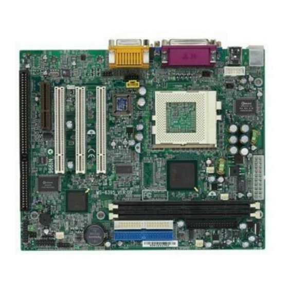
Chapter 1 Mainboard Layout Top : mouse Bottom: keyboard Power Supply Top : Parallel Port Bottom: COM Port & VGA Port D-LED CACHE Top : Game port Bottom: Line-Out Line-In PCI Slot 1 PCI Slot 2 PCI Slot 3 ISA Slot MS-6395 MICRO ATX Mainboard... -
Page 12: Quick Components Guide
Introduction Quick Components Guide The table below provides you the quick guide for setting up the system. Component Function Reference Socket 370 Installing CPU p. 2-2 DIMM1~2 Installing memory module p. 2-4 ATX Power Supply Installing power supply p. 2-6 Connecting to floppy disk drive p. -
Page 13: Key Features
Modem (Internal/External) Ring Wake Up function ● Suspend to RAM (optional) MSI Special Features The MSI special features are designed by MSI R&D which are only available in MSI mainboards. The MS-6395 mainboard is equipped with PC Alert III and T.O.P Tech III. -
Page 14: Pc Alert™ Iii
Introduction PC Alert™ III The PC Alert III is a utility you can find in the CD-ROM. The utility is just like your PC doctor that can detect the following PC hardware status during real time operation: ● monitor CPU & system temperature ●... - Page 15 Chapter 1 Features: ● Network Management - Monitoring & remote control ● Basic System Utilities - Scandisk & Defragment to maintain your HDD ● 3D Graphics Design - Enables a more friendly user interface ● Software Utilities - SoftCooler Optimized Cooling - Doctor Y2K diagnoses Y2K problems - BusRacing function adjusts F.S.B under Windows 95/98 - MoSpeed speeds up your modem transmission...
-
Page 16: D-Led
Introduction D-LED™ (optional) The D-LED™ uses graphic signal display to help users understand their system. Four LEDs embedded in the mainboard provide up to 16 combinations of signals to debug the system. The 4 LEDs can debug all problems that fail the system, such as VGA, RAM or other failures. - Page 17 Chapter 1 Processor Initialization - This will show information regarding the processor (like brand name, system bus, etc… ) Testing RTC (Real Time Clock) Initializing Video Interface - This will start detecting CPU clock, checking type of video onboard. Then, detect and initialize the video adapter. BIOS Sign On - This will start showing information about logo, processor brand name, etc…...
- Page 18 Hardware Setup Hardware Setup This chapter provides you with the information about hardware setup procedures. While doing the installation, be careful in holding the compo- nents and follow the installation procedures. For some components, if you install in the wrong orientation, the components will not work properly. Besides, please use a grounded wrist strap before handling computer components.
-
Page 19: Central Processing Unit: Cpu
Chapter 2 Central Processing Unit: CPU ® The mainboard supports Intel Celeron / Pentium III (FC-PGA) processors. The mainboard uses a CPU socket called Socket 370 for easy CPU installation. Make sure that the CPU has a Heat Sink and a cooling fan at- tached to prevent overheating. -
Page 20: Cpu Core Speed Derivation Procedure
Hardware Setup CPU Core Speed Derivation Procedure The mainboard can automatically set the CPU Host Bus Frequency Clock. CPU Clock 100MHz Core/Bus ratio then CPU core speed Host Clock x Core/Bus ratio 100MHz x 7 700MHz OVERCLOCKING This motherboard are designed to support overclocking. However, please make sure your components are able to tolerate such abnormal setting, while doing overclocking. -
Page 21: Memory Installation
Chapter 2 Memory Installation The mainboard provides 2 sockets for 168-pin, 3.3V SDRAM with 4 memory banks. To operate properly, at least one DIMM module must be installed. The mainboard supports the memory size up to 512MB. DIMM1 DIMM2 The DRAM Addressing & Size DRAM Address Size MB/DIMM... -
Page 22: Module Installation Procedures
Hardware Setup Module Installation Procedures You can install the single-sided or double-sided DIMM according to your needs. There are two notches on each DIMM. The pins on the either side of the breaks are different. Pay attention to the orientation as shown below. The module will only fit in the right orientation. -
Page 23: Power Supply
Chapter 2 Power Supply The mainboard supports ATX power supply for the power system. As the mainboard has the instant power on function, make sure that all compo- nents are installed properly before inserting the power supply connector to ensure that no damage will be done. ATX 20-pin Power Supply This connector allows you to connect to an ATX power supply. -
Page 24: Back Panel
Hardware Setup Back Panel The Back Panel provides the following connectors: Parallel Mouse Midi/Joystick COM A L-out L-in Keyboard USB Mouse Connector ® The mainboard provides a standard PS/2 mouse mini DIN connector ® ® for attaching a PS/2 mouse. You can plug a PS/2 mouse directly into this connector. -
Page 25: Keyboard Connector
Chapter 2 Keyboard Connector ® The mainboard provides a standard PS/2 keyboard mini DIN connec- ® ® tor for attaching a PS/2 keyboard. You can plug a PS/2 keyboard directly into this connector. SIGNAL DESCRIPTION Keyboard DATA Keyboard DATA No connection Ground Keyboard Clock Keyboard clock... -
Page 26: Parallel Port Connector
Hardware Setup Parallel Port Connector The mainboard provides a 25 pin female centronic connector for LPT. A parallel port is a standard printer port that also supports Enhanced Parallel Port (EPP) and Extended Capabilities Parallel Port (ECP). SIGNAL DESCRIPTION STROBE Strobe DATA0 Data0... -
Page 27: Serial Port Connectors: Com A
Chapter 2 Serial Port Connectors: COM A The mainboard has one 9-pin male DIN connector for serial port COM A. You can attach a mouse or other serial devices directly into this connector. SIGNAL DESCRIPTION Data Carry Detect Serial In or Receive Data SOUT Serial Out or Transmit Data 1 2 3 4 5... -
Page 28: Joystick/Midi Connector
Hardware Setup Joystick/Midi Connector You can connect game joysticks or game pads to this 15-pin female connector for playing game. You can also connect MIDI devices for playing or editing professional audio. Audio Port Connectors Line Out is a connector for headphone or speakers. Line In is used for external CD player, tape players or other audio devices to be recorded by your computer or played through the Line Out. -
Page 29: Connectors
Chapter 2 Connectors The mainboard provides the connectors to connect to FDD, USB, HDD, case, modem, LAN, FAN, smart card, power saving switch, IR module, CD- ROM and DVD add on card. Floppy Disk Drive Connector: FDD The mainboard provides a standard floppy disk drive connector that supports 360K, 720K, 1.2M, 1.44M and 2.88M floppy disk types. -
Page 30: Hard Disk Connectors: Ide1 & Ide2
Hardware Setup Hard Disk Connectors: IDE1 & IDE2 The mainboard has an IDE controller on the ICH chipset that provides IDE HDD/CD-ROM with PIO, Bus Master and Ultra DMA66/100 operations modes. It has two HDD connectors IDE1 (Primary) and IDE2 (Secondary). You can connect up to four hard disk drives, CD-ROM or 120MB Floppy to IDE1 and IDE2. -
Page 31: Com B Connector: Com B
Chapter 2 COM B Connector: COM B This connector is connected to a bracket containing the second serial port: COM B. COM B Chassis Intrusion Switch Connector: J1 This connector is connected to a 2-pin chassis switch. If the chassis is opened, the switch will be short. -
Page 32: Wake On Ring Connector: Jmdm1
Hardware Setup Wake On Ring Connector: JMDM1 This connector allows you to connect to a modem card with Wake On Ring function. The connector will power on the system when a signal is received through the modem card. MDM_WAKEUP 5VSB JMDM1 Wake On LAN Connector: JWOL1 This connector allows you to connect to a LAN card with Wake On... -
Page 33: Case Connector: Jfp1
Chapter 2 Case Connector: JFP1 The case connector block JFP1 allows you to connect the Power Switch, Reset Switch, Power LED, Speaker, and HDD LED. Reset Switch Power Switch Speaker Power HDD LED JFP1 2-16... - Page 34 Hardware Setup Power Switch Connect to a 2-pin push button switch. Reset Switch Reset switch is used to reboot the system rather than turning the power ON/OFF. Avoid rebooting while the HDD LED is lit. You can connect the Reset switch from the system case to this pin. Power LED The Power LED is lit while the system power is on.
-
Page 35: Fan Power Connectors
Chapter 2 Fan Power Connectors: CPUFAN/POWER_FAN/SYSFAN The CPUFAN (processor fan), PSFAN(power supply fan) and SYSFAN (system fan) support system cooling fan with +12V. It supports three pin head connector. When connecting the wire to the connector, always take note that the red wire is the positive and should be connected to the +12V, the black wire is Ground and should be connected to GND. -
Page 36: Irda Infrared Module Connector: Jir1
Hardware Setup IrDA Infrared Module Connector: JIR1 The mainboard provides one infrared (IR) connector for IR modules. This connector is for optional wireless transmitting and receiving infrared module. You must configure the setting through the BIOS setup to use the IR function. -
Page 37: Cd-In Connectors
Chapter 2 CD-In Connector This connector allows you to connect to CD-ROM audio connector. AUX Line-In Connector This connector is used for a DVD add-on card with line-in connector. Modem-In This connector is for Modem with internal voice connector. Mono_Out is connected to the Modem Speaker Out connector. -
Page 38: Front Audio Connector
Hardware Setup Front Audio Connector This connector is connected to the audio port on the front panel of your computer (if any). JGL1 2-21... -
Page 39: Jumpers
Chapter 2 Jumpers The motherboard provides the following jumpers for you to set the computer’s function. Besides jumper settings, some of the motherboard’s onboard functions are adjusted through the DIP switches. This section will mention how to change your motherboard’s function through the use of jump- ers and/or switches. -
Page 40: Bios Flash Jmper: Jp1
Hardware Setup BIOS Flash Jumper: JP1 This jumper is used to locked/unlocked BIOS Flash. This jumper should be unlock when flashing/programming the BIOS. BIOS Flash BIOS Flash Unlocked Locked Onboard Audio Jumper: JP2 This jumper is used to enable/disable the onboard soft audio codec. Enabled Disabled (default) - Page 41 Chapter 2 Front Audio Jumper: JP3 This jumper is used to set the function of onboard audio and front audio (when connected). “Close” the jumper to enable both the onboard audio port and front audio port. “Open” the jumper to disable the onboard audio port but enable the front audio port only.
-
Page 42: Slots
Hardware Setup Slots The motherboard provides one CNR (Communication and Network Riser) slot, three 32-bit Master PCI Bus Slots, and one ISA slot. PCI Slot CNR Slot ISA Slot PCI Slots The three PCI slots allow you to insert the expansion cards according to your needs. -
Page 43: Pci Interrupt Request
Chapter 2 PCI Interrupt Request The IRQ, abbreviation of interrupt request line, and pronounced I-R-Q, are hardware lines over which devices can send interrupt signals to the microprocessor. The PCI IRQ pins are typically connected to the PCI bus INTA#-INTD# pins as follows. PCI Slot1 INT A# INT B# INT C# INT D# PCI Slot2 INT B# INT C# INT D# INT A# PCI Slot3 INT C# INT D# INT A# INT B#... -
Page 44: Chapter 3 Award
Award ® BIOS Setup ® Chapter 3 Award BIOS Setup ® Award BIOS Setup ® This mainboard uses Award BIOS ROM that has a built-in Setup pro- gram to allow users to modify the basic system configuration. The information is stored in battery-backed RAM (CMOS RAM) so that it retains the Setup information when the power is turned off. -
Page 45: Entering Setup
Chapter 3 Entering Setup Power on the computer. When the below message appears briefly at the bottom of the screen during the POST (Power On Self Test), press <Del> key or simultaneously press <Ctrl>, <Alt>, and <Esc> keys to enter Setup. TO ENTER SETUP BEFORE BOOT, PRESS <CTRL-ALT-ESC>... -
Page 46: Getting Help
Award ® BIOS Setup Getting Help After entering the Setup program, the first screen you will see is the Main Menu. Main Menu The main menu lists the setup functions you can make changes to. You can use the control keys ( ? ?? ? ?? to select the item. The on-line description of the highlighted setup function is displayed at the bottom of the screen. -
Page 47: Main Menu
Chapter 3 Main Menu ® Once you enter Award BIOS CMOS Setup Utility, the Main Menu will appear on the screen. The Main Menu allows you to select from twelve setup functions and two exit choices. Use arrow keys to select among the items and press <Enter>... - Page 48 Award ® BIOS Setup Power Management Setup Use this menu to specify your settings for power management. PnP/PCI Configuration This entry appears if your system supports PnP/PCI. PC Health Status This entry shows your PC health status. Frequency/Voltage Control Use this menu to specify your settings for frequency/voltage control. Load Fail-Safe Defaults Use this menu to load the BIOS default values for the minimal/stable performance for your system to operate.
-
Page 49: Standard Cmos Features
Chapter 3 Standard CMOS Features The items in Standard CMOS Setup Menu are divided into 13 categories. Each category includes none, one or more than one setup items. Use the arrow keys to highlight the item and then use the <PgUp> or <PgDn> keys to select the value you want in each item. - Page 50 Award ® BIOS Setup Time This item allows you to set the system to the time that you specify (usually the current time). The time format is <hour> <minute> <second>. PrimaryMaster/PrimarySlave/SecondaryMaster/Secondary Slave Press PgUp/<+> or PgDn/<-> to select the hard disk drive category. The specification of hard disk drive will show on the right hand according to your selection.
- Page 51 Chapter 3 Drive A, Drive B This item allows you to set the type of floppy drivers installed. Avail- able options are: [None] , [360K, 5.25in] , [1.2M, 5.25in] , [720k, 3.5in] , [1.44M, 3.5in] and [2.88M, 3.5in]. Default value for Drive A is [1.44M, 3.5in], and for Drive B is [None].
-
Page 52: Advanced Bios Features
Award ® BIOS Setup Advanced BIOS Features CMOS Setup Utility - Copyright(C) 1984-2001 Award Software Advanced BIOS Features Item Help Anti-Virus Protection [Disabled] CPU Internal Cache [Enabled] Menu Level External Cache [Enabled] CPU L2 Cache ECC Checking [Enabled] Allows you to choose the Processor Number Feature [Enabled] VIRUS warning feature for... - Page 53 Chapter 3 CPU Internal Cache This item allows you to choose from the default of [Enabled] or choose [Disabled] to turn on or off the CPU’ s internal cache (L1 cache). Available options are [Disabled] and [Enabled]. ?Note: The internal cache is built in the processor. External Cache This item allows you to choose from the default of [Enabled] or choose [Disabled] to control the function of level 2 cache memory.
- Page 54 Award ® BIOS Setup Boot Other Device This function allows the system to try to boot from other device if the system fails to boot from the 1st/2nd/3rd boot device. Swap Floppy Drive This item allows you to choose from the default of [Disabled] or choose [Enabled] to switch the floppy disk drives between being designated as A and B.
- Page 55 Chapter 3 Typematic Rate (Chars/Sec) This item allows you to set the number of times a second to repeat a keystroke when you hold the key down. Available options are [6], [8], [10], [12], [15], [20], [24], and [30]. Default value is [6]. Typematic Delay (Msec) This item allows you to set the delay time before the key begins to repeat the keystroke while holding down the key.
- Page 56 Award ® BIOS Setup HDD S.M.A.R.T Capability This item allows you to set the HDD S.M.A.R.T capability. S.M.A.R.T is a utility that monitors your disk hardware with the goal of identifying disks that have a strong possibility of crashing. This provides you a window of opportunity to gracefully remove data from a failing disk and take it offline before your disk drive takes you offline.
-
Page 57: Advanced Chipset Features
Chapter 3 Advanced Chipset Features CMOS Setup Utility - Copyright(C) 1984-2001 Award Software Advanced Chipset Features Item Help SDRAM CAS Latency Time [Auto] SDRAM Cycle Time Tras/Trc [6/8] SDRAM RAS-to-CAS Delay Menu Level SDRAM RAS Precharge Time System BIOS Cacheable [Disabled] Video BIOS Cacheable [Disabled]... - Page 58 Award ® BIOS Setup SDRAM RAS-to-CAS Delay This item allows you to control the latency between the SDRAM active command and the read/write command. Available options are [3] and [2]. Default value is [3]. SDRAM RAS Prechange Time This item allows you to control the idle clocks after issuing a prechange command to the SDRAM.
- Page 59 Chapter 3 CPU Latency Timer This item allows you to control the GMCH’ s response to CPU defer- rable cycles. Available options are [Disabled] and [Enabled]. Default value is [Disabled]. Delayed Transaction The chipset has an embedded 32-bit posted write buffer to support delay transactions cycles.
- Page 60 Award ® BIOS Setup Paging Mode Control This item allows you to select the paging mode control. Available options are [Open] and [Close]. Default value is [Open]. RAS-to-CAS Override This items allows you to insert a timing delay between the CAS and RAS strobe signals, used when Onboard Display Cache is written to, read from, or refreshed.
-
Page 61: Integrated Peripherales
Chapter 3 Integrated Peripherales CMOS Setup Utility - Copyright(C) 1984-2001 Award Software Integrated Peripherales On-Chip Primary PCI IDE [Enabled] Item Help On-Chip Secondary PCI IDE [Enabled] IDE Primary Master PIO [Auto] Menu Level IDE Primary Slave PIO [Auto] IDE Secondary Master PIO [Auto] IDE Secondary Slave PIO [Auto]... - Page 62 Award ® BIOS Setup OnChip Primary/Secondary PCI IDE The integrated peripheral controller contains an IDE interface with sup- port for two IDE channels. Choose the default of [Enabled] to activate each channel separately. Available options are [Enabled] and [Disabled]. Default value is [Enabled].
- Page 63 Chapter 3 Init Display First This item allows you to decide to activate whether PCI Slot or AGP Slot. Available options are [PCI Slot] and [Onboard]. Default value is [PCI Slot]. AC97 Audio/AC97 Modem Set [Auto] to allow the motherboard’ s BIOS to detect whether you are using any audio/modem device or not.
- Page 64 Award ® BIOS Setup Hot Key Power ON This item allows you to set the hot key power on function while the system is turned off. Default value is [Ctrl-F1]. Onboard FDC Controller Select [Enabled] if your system has a floppy disk controller (FDC) in- stalled on the system board and you wish to use it.
- Page 65 Chapter 3 Parallel Port Mode This item allows you to set the onboard parallel port mode. Available options are [SPP], [EPP], [ECP], and [ECP+EPP]. Default value is [SPP]. Standard Parallel Port EPP : Enhanced Parallel Port ECP : Extended Capability Port EPP Mode Select This item allows you to select the type of EPP mode.
- Page 66 Award ® BIOS Setup Midi Port IRQ This item allows you to set the Midi Port IRQ. Available options are [5] and [10]. Default value is [10]. Power Status Led This item allows you to choose the type of Power Status Led. Avail- able options are [Single], [Dual], and [Blinking].
-
Page 67: Power Management Setup
Chapter 3 Power Management Setup The Power Management Setup allows you to configure you system to most effectively save energy while operating in a manner consistent with your own style of computer use. CMOS Setup Utility - Copyright(C) 1984-2001 Award Software Power Management Setup IPCA Function [Enabled]... - Page 68 Award ® BIOS Setup IPCA Function This item allows you to set ACPI (Advanced Configuration and Power Management) function. Available options are [Enabled] and [Disabled]. Default value is [Enabled]. ACPI Suspend Type This item allows you to set the ACPI suspend type you will use. Available options are [S1 (POS)] and [S3 (STR)].
- Page 69 Chapter 3 Video Off Method This item determines the manner in which the monitor is blanked. V/H SYNC+Blank This option will cause the system to turn off the vertical and horizontal synchronization ports and write blanks to the video buffer. Blank Screen This option only writes blanks to video buffer.
- Page 70 Award ® BIOS Setup HDD Power Down This item allows you to set the time period before the hard disk drive will be powered down while all other devices remain active. Available options are [Disabled] and [1/2/3/4/5/6/7/8/9/10/11/12/13/14/15 Min]. Default value is [Disabled].
- Page 71 Chapter 3 USB KB Wake-Up From S3 When set to [Enabled], pressing USB keyboard will wake up the system from shutdown in “ Suspend to RAM” mode. Available options are [Enabled] and [Disabled]. Default value is [Disabled]. CPUThermal-Throttling This item allows you to select the CPU Thermal-Throttling rate. Available options are [12.5/25.0/37.5/50.0/62.5/75.0/87.5 %].
-
Page 72: Pnp/Pci Configurations
Award ® BIOS Setup PnP/PCI Configurations This section describes configuring the PCI bus system. PCI (Personal Computer Interconnect) is a system which allows I/O devices to operate at speeds nearing the speed the CPU itself uses when communicating with its own special components. - Page 73 Chapter 3 Resource Controlled By The Award Plug and Play BIOS has the capacity to automatically configure all of the boot and Plug and Play compatible devices. However, this capability means absolutely nothing unless you are using a Plug and Play operating system such as Windows 95/98.
-
Page 74: Pc Health Status
Award ® BIOS Setup PC Health Status This section helps you to get more information about your system including CPU temperature, FAN speed and voltages. It is recommended that you contact with your motherboard supplier to get proper value about your setting of the CPU temperature. - Page 75 Chapter 3 Vcore This item shows the current system voltage. Chassis Intrusion Detect When set to [Enabled], any intrusion on the system chassis will be recorded. The next time you turn on the system, it will show a warning mes- sage on the screen.
-
Page 76: Frequency/Voltage Control
Award ® BIOS Setup Frequency/Voltage Control This section is for setting CPU Frequency/Voltage Control. CMOS Setup Utility - Copyright(C) 1984-2001 Award Software Frequency/Voltage Control Auto Detect DIMM/PCI Clk [Enabled] Item Help CPU Host/SDRAM/PCI Clk/Sst [Default] CPU Clock Ratio [Auto] Menu Level ? ? ? ? ? ? ? ? Move Enter:Select +/-/PU/PD:Value F10:Save ESC:Exit F1:General Help F5:Previous Values F6:Fail-safe Defaults F7:Optimized Defaults Auto Detect DIMM/PCI CLK... -
Page 77: Load Fail-Safe Defaults
Chapter 3 Load Fail-Safe Defaults When you select this function, a message as below will appear on the screen: CMOS Setup Utility - Copyright(C) 1984-2001 Award Software Standard CMOS Features Frequency/Voltage Control Advanced BIOS Features Load Fail-Safe Defaults Advanced Chipset Features Load Optimized Defaults Integrated Peripherals Set Supervisor Password... -
Page 78: Load Optimized Defaults
Award ® BIOS Setup Load Optimized Defaults When you select this function, a message as below will appear on the screen: CMOS Setup Utility - Copyright(C) 1984-2001 Award Software Standard CMOS Features Frequency/Voltage Control Advanced BIOS Features Load Fail-Safe Defaults Advanced Chipset Features Load Optimized Defaults Integrated Peripherals... -
Page 79: Set Supervisor/User Password
Chapter 3 Set Supervisor/User Password When you select this function, a message as below will appear on the screen: CMOS Setup Utility - Copyright(C) 1984-2001 Award Software Standard CMOS Features Frequency/Voltage Control Advanced BIOS Features Load Fail-Safe Defaults Advanced Chipset Features Load Optimized Defaults Integrated Peripherals Set Supervisor Password... - Page 80 Award ® BIOS Setup Additionally, when a password is enabled, you can also require the BIOS to request a password every time your system is rebooted. This would prevent unauthorized use of your computer. You determine when the password is required within the BIOS Features Setup Menu and its Security option.
-
Page 81: Save & Exit Setup
Chapter 3 Save & Exit Setup When you want to quit the Setup menu, you can select this function to save the data. A message as below will appear on the screen: CMOS Setup Utility - Copyright(C) 1984-2001 Award Software Standard CMOS Features Frequency/Voltage Control Advanced BIOS Features... -
Page 82: Exit Without Saving
Award ® BIOS Setup Exit without Saving When you want to quit the Setup menu, you can select this function without saving the data. A message as below will appear on the screen: CMOS Setup Utility - Copyright(C) 1984-2001 Award Software Standard CMOS Features Frequency/Voltage Control Advanced BIOS Features... -
Page 83: Glossary
Glossary Glossary Buffer A temporary storage area, usually in RAM. The purpose of most buffers is to act as a holding area, enabling CPU to manipulate data before transferring it to a device. A collection of wires through which data is transmitted from one part of a computer to another. - Page 84 DIMM Short for dual in-line memory module, a small circuit board that holds memory chips. A single in-line memory module (SIMM) has a 32-bit path to the memory chips whereas a DIMM has 64-bit path. Abbreviation of either Intelligent Drive Electronics or Integrated Drive Electronics, depending on who you ask.
- Page 85 Glossary Acronym for Peripheral Component Interconnect, a local bus standard devel- oped by Intel Corporation. Most modern PCs include a PCI bus in addition to a more general ISA expansion bus. PS/2 Port A type of port developed by IBM for connecting a mouse or keyboard to a PC. The PS/2 port supports a mini DIN plug containing just 6 pins.