
Related Manuals for MSI MS-6391


Summary of Contents for MSI MS-6391
- Page 1 845 PRO4 MICRO-STAR INTERNATIONAL MS-6391 ATX Mainboard Version 1.0 G52-MA00362...
- Page 2 Shielded interface cables and A.C. power cord, if any, must be used in order to comply with the emission limits. VOIR LA NOTICE D’INSTALLATION AVANT DE RACCORDER AU RESEAU. Micro-Star International MS-6391 Tested to comply with FCC Standard For Home or Office Use...
-
Page 3: Copyright Notice
Copyright Notice The material in this document is the intellectual property of MICRO- STAR INTERNATIONAL. We take every care in the preparation of this document, but no guarantee is given as to the correctness of its contents. Our products are under continual improvement and we reserve the right to make changes without notice. -
Page 4: Safety Instructions
Safety Instructions Always read the safety instructions carefully. Keep this User’s Manual for future reference. Keep this equipment away from humidity. Lay this equipment on a reliable flat surface before setting it up. The openings on the enclosure are for air convection hence protects the equipment from overheating. -
Page 5: Table Of Contents
Mainboard Specifications ..............1-2 Mainboard Layout ................1-4 Quick Components Guide ............... 1-5 Key Features ..................1-6 MSI Special Features ................ 1-7 PC Alert™ III ................1-7 Fuzzy Logic™ III ................ 1-9 D-LED™ ..................1-10 Chatper 2 Hardware Setup ..............2-1 Central Processing Unit: CPU ............ - Page 6 LAN Jack (RJ-45) (optional) ............ 2-13 Parallel Port Connector: LPT1 ..........2-14 Connectors ..................2-15 Floppy Disk Drive Connector: FDD1 ........2-15 Hard Disk Connectors: IDE1 & IDE2 ........2-16 Fan Power Connectors: P_FAN1/C_FAN1/S_FAN1 ..2-17 Case Connector: F_P1 & F_P2 (optional) ......2-18 Power Saving Switch Connector: JGS1 .........
- Page 7 Advanced BIOS Features ..............3-9 Advanced Chipset Features ............3-14 Integrated Peripherales ..............3-17 Power Management Setup ............. 3-22 PnP/PCI Configurations ............... 3-27 PC Health Status ................3-29 Frequency/Voltage Control ............3-31 Load Fail-Safe/Optimized Defaults ..........3-33 Set Supervisor/User Password ............. 3-34 Save &...
- Page 8 Introduction Introduction The 845 Pro4 (MS-6391) ATX mainboard is a high-performance computer mainboard based on Intel 82845 & 82801BA chipsets. The ® 845 Pro4 is designed for Intel Pentium 4 processor in the 478 pin ® ® package that delivers a high performance and professional desktop platform solution.
-
Page 9: Mainboard Specifications
Chapter 1 Mainboard Specifications Support Intel Pentium 4 processor in FC-PGA2 package ® ® Support 1.3GHz, 1.4GHz and up to 2GHz Chipset Intel 845 chipset (593 FC-BGA) ® - Support 400MHz Intel NetBurst micro-architecture bus - Support SDRAM at 133MHz operation (PC133) - 100MHz FSB - AGP 2x/4x universal slot Intel... - Page 10 Introduction On-Board Peripherals On-Board Peripherals include: - One floppy port supports two FDDs with 360KB, 720KB, 1.2MB, 1.44MB and 2.88MB. - Two serial ports (COM A + COM B) - One parallel port supports SPP/EPP/ECP mode - Four USB ports (Rear * 2/Front * 2) - One RJ-45 connector (optional) - One audio/game port Audio...
-
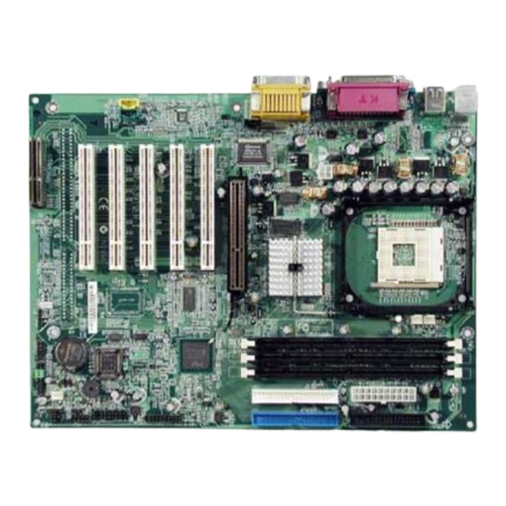
Page 11: Mainboard Layout
Codec PCI Slot 2 USB1 JGS1 USB2 (optional) PCI Slot 3 MDM_IN1 Winbond W83628F PCI Slot 4 AUX_IN1 F_P1 PCI Slot 5 JGL1 JBAT1 BATT S_FAN1 ISA Slot (optional) JWOL1 JAUDIO2 Winbond (optional) W83629D JP1(optional) JMDM1 JAUDIO1 MS-6391 ATX Mainboard... -
Page 12: Quick Components Guide
Introduction Quick Components Guide Component Function Reference Socket 478 Installing CPU p. 2-2 DIMM 1~3 Installing DIMMs p. 2-7 ATX Power Connector Installing power supply p. 2-8 JPW1 Connecting to a 12V power p. 2-8 FDD1 Connecting to Floppy disk drive p. -
Page 13: Key Features
Chapter 1 Key Features ATX Form Factor CPU: Intel Pentium 4 processor in FC-PGA2 package (Socket 478) ® ® AGP 4x support AC’ 97 audio integrated Easy to install USB PC 2 PC networking function LAN Wake Up Function Modem (Internal) Ring Wake Up Function T.O.P Tech™... -
Page 14: Msi Special Features
Introduction MSI Special Features The MSI special features are designed and developed by MSI R&D, which are only available in MSI mainboards. The MS-6391 mainboard is OPTIONALLY equipped with the following features: PC Alert™ III The PC Alert III is a utility you can find in the CD-ROM disk. - Page 15 Chapter 1 Features: Network Management - Monitoring & remote control Basic System Utilities - Scandisk & Defragment to maintain your HDD 3D Graphics Design - Enables a more friendly user interface Software Utilities - SoftCooler Optimized Cooling...
-
Page 16: Fuzzy Logic™ Iii
Introduction Fuzzy Logic™ III The Fuzzy Logic™ III utility allows users to overclock the CPU FSB (Front Side Bus) frequency in the Windows environment. Select the CPU frequency you prefer and click “Go” button to apply the frequency or click “Save” button allowing the system to run at the specified frequency each time when the system is powered on. -
Page 17: D-Led
Chapter 1 D-LED™ The D-LED™ uses graphic signal display to help users understand their system. Four LEDs em- bedded in the mainboard provide up to 16 combina- tions of signals to debug the system. The 4 LEDs can debug all problems that fail the system, such as VGA, RAM or other failures. - Page 18 Introduction D-LED Description Processor Initialization - This will show information regarding the processor (like brand name, system bus, etc…) Testing RTC (Real Time Clock) Initializing Video Interface - This will start detecting CPU clock, checking type of video onboard. Then, detect and initialize the video adapter. BIOS Sign On - This will start showing information about logo, processor brand name, etc….
-
Page 19: Hardware Setup
Hardware Setup Hardware Setup This chapter provides you with the information about hardware setup procedures. While doing the installation, be careful in holding the components and follow the installation procedures. For some components, if you install in the wrong orientation, the components will not work properly. -
Page 20: Central Processing Unit: Cpu
Chapter 2 Central Processing Unit: CPU The mainboard supports Intel Pentium 4 processor in FC-PGA2 ® ® package. The mainboard uses a CPU socket called PGA478 for easy CPU installation. When you are installing the CPU, make sure the CPU has a heat sink and a cooling fan attached on the top to prevent overheating. -
Page 21: Cpu Core Speed Derivation Procedure
Hardware Setup CPU Core Speed Derivation Procedure CPU Clock 100MHz Core/Bus ratio then CPU core speed Host Clock x Core/Bus ratio 100MHz x 14 1.4GHz 1. Overheating The issue of heat will seriously damage the CPU and system, always make sure the cooling fan can work prop- erly to protect the CPU from overheating. -
Page 22: Installing The Cpu Fan
Chapter 2 Installing the CPU Fan As processor technology pushes to faster speeds and higher performance, thermal managment becomes increasingly important. To dissipate heat, you need to attach the CPU cooling fan and heatsink on top of the CPU. Follow the instructions below to install the heatsink/ fan. - Page 23 Hardware Setup 3. Mount the fan on top of the heatsink. Press down the fan until its four clips get wedged in the holes of the retention mechanism. levers 4. Press the two levers down to fasten the fan. Each lever can be pressed down in only ONE direction.
-
Page 24: Memory Installation
Chapter 2 Memory Installation Memory Bank Configuration The mainboard supports a maximum memory size of 3GB. It provides three 168-pin unbuffered SDRAM DIMM (Double In-Line Memory Module) sockets and supports 64MB to 512MB technology. DIMM 1 ~ 3 Synchronous DRAM is a type of dynamic RAM memory chip that has been widely used starting in the latter part of the 1990s. -
Page 25: Memory Installation Procedures
Hardware Setup Memory Installation Procedures You can install memory modules in any combination as follows: Socket Memory Module Total Memory Socket 1 64MB, 128MB, 64MB ~ 1GB (Bank0 & Bank1) 256MB, 512MB, 1GB Socket 2 64MB, 128MB, 64MB ~ 1GB (Bank2 &... -
Page 26: Power Supply
Chapter 2 Power Supply The mainboard supports ATX power supply for the power system. Before inserting the power supply connector, always make sure that all components are installed properly to ensure that no damage will be caused. ATX 20-Pin Power Connector This connector allows you to connect to an ATX power supply. - Page 27 Hardware Setup JPW1 ATX Power Connector SIGNAL SIGNAL 3.3V 3.3V 3.3V -12V PS_ON SIGNAL PW_OK 5V_SB JPW1 Pin Definition ATX Power Connector Pin Definition...
-
Page 28: Back Panel
Chapter 2 Back Panel The Back Panel provides the following connectors: Mouse Paraller Port Midi/Joystick Port Keyboard USB Ports COM A COM B L-Out L-In MIC Mouse Connector The mainboard provides a standard PS/2 mouse mini DIN con- ® nector for attaching a PS/2 mouse. -
Page 29: Keyboard Connector
Hardware Setup Keyboard Connector The mainboard provides a standard PS/2 keyboard mini DIN ® connector for attaching a PS/2 keyboard. You can plug a PS/2 key- ® ® board directly into this connector. SIGNAL DESCRIPTION Keyboard DATA Keyboard DATA No connection Ground Keyboard Clock Keyboard clock... -
Page 30: Serial Port Connectors: Com A & Com B
Chapter 2 Serial Port Connector: COM A & COM B The mainboard offers two 9-pin male DIN connectors for serial port COM A and COM B. The ports are 16550A high speed communica- tion ports that send/receive 16 bytes FIFOs. You can attach a serial mouse or other serial devices directly to them. -
Page 31: Lan Jack (Rj-45) (Optional)
Hardware Setup LAN Jack (RJ-45) (optional) The mainboard provides one standard RJ-45 jack for connection to Local Area Network (LAN). You can connect a network cable to the LAN jack. SIGNAL DESCRIPTION Receive Differential Pair Receive Differential Pair Ground Ground Ground Ground LAN RJ-45 Jack... -
Page 32: Parallel Port Connector: Lpt1
Chapter 2 Parallel Port Connector: LPT1 The mainboard provides a 25-pin female centronic connector for LPT. A parallel port is a standard printer port that supports Enhanced Parallel Port (EPP) and Extended Capabilities Parallel Port (ECP) mode. SIGNAL DESCRIPTION STROBE Strobe DATA0 Data0... -
Page 33: Connectors
Hardware Setup Connectors The mainboard provides connectors to connect to FDD, IDE HDD, case, modem, LAN, USB Ports, IR module and fans. Floppy Disk Drive Connector: FDD1 The mainboard provides a standard floppy disk drive connector that supports 360K, 720K, 1.2M, 1.44M and 2.88M floppy disk types. FDD1 2-15... -
Page 34: Hard Disk Connectors: Ide1 & Ide2
Chapter 2 Hard Disk Connectors: IDE1 & IDE2 The mainboard has a 32-bit Enhanced PCI IDE and Ultra DMA 33/66/100 controller that provides PIO mode 0~4, Bus Master, and Ul- tra DMA/33/66/100 function. It has two HDD connectors: IDE1 (Primary) and IDE2 (Secondary). You can connect up to four hard disk drives, CD-ROM or 120MB Floppy to IDE1 and IDE2. -
Page 35: Fan Power Connectors: P_Fan1/C_Fan1/S_Fan1
Hardware Setup Fan Power Connectors: P_FAN1/C_FAN1/S_FAN1 The C_FAN1 (processor fan), S_FAN1 (system fan) and P_FAN1 (power supply fan) support system cooling fan with +12V. They support 3-pin head connector. When connecting the wire to the connector, always take note that the red wire is the positive and should be connected to the +12V, the black wire is Ground and should be connected to GND. -
Page 36: Case Connector: F_P1 & F_P2 (Optional)
Chapter 2 Case Connector: F_P1 & F_P2 (optional) The case connector block F_P1 allows you to connect the Power Switch, Reset Switch, Power LED, Speaker, HDD LED. The other case connector block F_P2 is compliant to Intel Front Panel I/O Connectivity Design Guide and can connect to the the Power Switch, Reset Switch, Power LED and HDD LED on the case. -
Page 37: Power Switch
Hardware Setup Power Switch Connect to a 2-pin push button switch. Reset Switch Reset switch is used to reboot the system rather than turning the power ON/OFF. Avoid rebooting while the HDD is working. You can connect the Reset switch from the system case to this pin. Power LED (F_P1) The Power LED is lit while the system power is on. -
Page 38: Hdd Led
Chapter 2 Power LED (F_P2) The Power LED is lit while the system power is on. There are two types of LEDs you can connect from the system case to the pin: 2-pin single color power LED: The power LED is not able to change its color. -
Page 39: Power Saving Switch Connector: Jgs1
Hardware Setup Power Saving Switch Connector: JGS1 Attach a power saving switch to this connector. Pressing the switch once will have the system enter the sleep/suspend state. Press any key to wake up the system. JGS1 2-21... -
Page 40: Power Saving Led Connector: Jgl1
Chapter 2 Power Saving LED Connector: JGL1 JGL1 is connected to a power saving LED. There are two types of LED that you can use: 3-pin or 2-pin (ACPI request) LED. If connected to a dual color LED, the LED light is green when system in turned on, and turns to orange color while entering the sleep state. -
Page 41: Wake On Ring/Wake On Lan Connectors
Hardware Setup Wake On Ring/Wake On LAN Connectors: JMDM1/JWOL1 Wake On Ring (JMDM1) connector allows you to connect to a modem card with Wake On Ring function; Wake On LAN (JWOL1) con- nector allows you to connect to a LAN card with Wake On LAN function. The two connectors provide system the feature to boot up when a signal is received through the modem card/local area network. - Page 42 Chapter 2 CD-In Connector This connector allows you to connect to CD-ROM audio connector. AUX Line-In Connector This connector is used for a DVD add-on card with line-in connector. Modem-In Connector This connector is for Modem with internal voice connector. Mono_Out is connected to the Modem Speaker Out connector.
-
Page 43: Irda Infrared Module Connector: Ir1 & Ir2 (Optional)
Hardware Setup IrDA Infrared Module Connector: IR1 & IR2 (optional) These connectors allow you to connect to IrDA Infrared modules. You must configure the setting through the BIOS setup to use the IR function. The difference between IR1 & IR2 is that IR2 is compliant to Intel Front Panel I/O Connectivity Design Guide. -
Page 44: Usb Front Connector: Usb1 & Usb2 (Optional)
Chapter 2 USB Front Connector: USB1 & USB2 (optional) The mainboard provides two Front USB (Universal Serial Bus) pin headers that allow you to connect optional USB ports for front panel. Different from USB1, USB2 is compliant to Intel Front Panel I/O Con- nectivity Design Guide. -
Page 45: Front Audio Connector: Jaudio1 & Jaudio2 (Optional)
Hardware Setup Front Panel Audio Header: JAUDIO1 & JAUDIO2 (optional) You can connect an optional audio connector to the Front Panel Audio Header. JAUDIO2 is compliant to Intel Front Panel I/O Connectivity Design Guide. JAUDIO1 JAUDIO2 2-27... - Page 46 Chapter 2 Description Description Active LINE Out(R) Active LINE Out(L) GND (aLO) GND (aLO) GND (+12) GND (+12) +12V (1A) (Cut Away) GND (MIC) Front LINE Out(R) LINE Next(R) Front LINE Out(L) LINE Next(L) GND (fLO) (Cut away) Line In(R) Line In(L) JAUDIO1 Pin Definition Caution!!!
-
Page 47: Jumpers
Hardware Setup Jumpers The mainboard provides the following jumpers for you to set the computer’s function. This section will mention how to change your mainboard’s function through the use of jumpers. Clear CMOS Jumper: JBAT1 There is a CMOS RAM on board that has a power supply from external battery to keep the data of system configuration. -
Page 48: Onboard Audio Jumper: Jp1 (Optional)
Chapter 2 Onboard Audio Jumper: JP1 (optional) This jumper is used to enable/disable the onboard soft audio codec. Auto Disabled (default) 2-30... -
Page 49: Slots
Hardware Setup Slots The motherboard provides one AGP slot, five 32-bit Master PCI bus slots, one ISA slot and one CNR slot. AGP Slot PCI Slot ISA Slot CNR Slot AGP (Accelerated Graphics Port) Slot The AGP slot allows you to insert the AGP graphics card. AGP is an interface specification designed for the throughput demands of 3D graphics. -
Page 50: Isa (Industry Standard Architecture) Slot (Optional)
Chapter 2 ISA (Industry Standard Architecture) Slot (optional) The ISA slot provides one 16-bit interface that are used to add expansion card to the computer. CNR (Communication & Networking Riser) Slot The CNR slot allows you to insert the CNR expansion cards. CNR is a specially designed network, audio, or modem riser card for ATX family motherboards. -
Page 51: Chapter 3 Award ® Bios Setup
Award BIOS Setup ® Chapter 3 Award BIOS Setup ® Award BIOS Setup ® This mainboard uses Award BIOS ROM that has a built-in Setup ® program to allow users to modify the basic system configuration. The information is stored in battery-backed RAM (CMOS RAM) so that it retains the Setup information when the power is turned off. -
Page 52: Entering Setup
Chapter 3 Entering Setup Power on the computer. When the below message appears briefly at the bottom of the screen during the POST (Power On Self Test), press <Del> key or simultaneously press <Ctrl>, <Alt>, and <Esc> keys to enter Setup. TO ENTER SETUP BEFORE BOOT, PRESS <CTRL-ALT-ESC>... -
Page 53: Getting Help
Award BIOS Setup ® Getting Help After entering the Setup program, the first screen you will see is the Main menu. Main Menu The Main menu lists the setup functions you can make changes to. You can use the control keys ( ↑ , ↓ ) to select the item. The on-line description of the highlighted setup function is displayed at the bottom of the screen. -
Page 54: Main Menu
Chapter 3 Main Menu Once you enter Award BIOS CMOS Setup Utility, the Main ® Menu will appear on the screen. The Main Menu allows you to select from twelve setup functions and two exit choices. Use arrow keys to select among the items and press <Enter>... -
Page 55: Power Management Setup
Award BIOS Setup ® Power Management Setup Use this menu to specify your settings of power management. PnP/PCI Configurations This entry appears if your system supports PnP/PCI. PC Health Status This entry shows your PC health status. Frequency/Voltage Control Use this menu to specify your settings of frequency/voltage control. Load Fail-Safe Defaults Use this menu to load the BIOS default values of your system for the minimal/stable performance to operate. -
Page 56: Standard Cmos Features
Chapter 3 Standard CMOS Features The items in Standard CMOS Features menu are divided into 13 categories. Each category includes none, one or more than one setup items. Use the arrow keys to highlight the item and then use the <PgUp> or <PgDn>... - Page 57 Award BIOS Setup ® Time (hh:mm:ss) This item allows you to set the system to the time that you specify (usually the current time). The time format is <hour> <minute> <second>. IDE Primary Master/IDE Primary Slave/ IDE Secondary Master/IDE Secondary Slave Press PgUp/<+>...
- Page 58 Chapter 3 Drive A/B The two items allow you to set the type of floppy drivers installed. Avail- able options are [None], [360K, 5.25 in], [1.2M, 5.25 in], [720k, 3.5 in], [1.44M, 3.5in], and [2.88M, 3.5in]. Default value for Drive A is [1.44M, 3.5in], and for Drive B is [None].
-
Page 59: Advanced Bios Features
Award BIOS Setup ® Advanced BIOS Features CMOS Setup Utility - Copyright(C) 1984-2001 Award Software Advanced BIOS Features Anti-Virus Protection [Disabled] Item Help CPU L1 & L2 Cache [Enabled] Quick Boot [Disabled] Menu Level 1st Boot Device [Floppy] 2nd Boot Device [HDD-0] Allows you to choose the 3rd Boot Device... -
Page 60: Quick Boot
Chapter 3 CPU L1 & L2 Cache Cache memory is additional memory that is much faster than the system memory. When the CPU requests data, the system transfers the requested data from the main memory into cache memory, for even faster access by the CPU. -
Page 61: Gate A20 Option
Award BIOS Setup ® Seek Floppy This function allows the system to check if floppy installed or uninstalled when booting up the computer. Available options are [Disabled] and [Enabled]. Default value is [Disabled]. Boot Up Num-Lock LED This item allows you to set the NumLock status when you boot up your computer. -
Page 62: Security Option
Chapter 3 Security Option This item allows you to limit access to the system and Setup program, or just to Setup program. When set to [Setup], the system will boot, but access to Setup program will be denied if the correct password is not entered at the prompt. - Page 63 Award BIOS Setup ® BIOS Flash Write Control The item is used to enable or disable the BIOS Flash Write Control for non-Award flash utility. Select [Enabled] when performing BIOS update with the non-Award flash utility. Ignore this option if you use the Award flash utility.
-
Page 64: Advanced Chipset Features
Chapter 3 Advanced Chipset Features CMOS Setup Utility - Copyright(C) 1984-2001 Award Software Advanced Chipset Features Item Help Configure DRAM Timing [by SPD] CAS# Latency Menu Level Prechare Delay RAS# to CAS# Delay RAS# Precharge DRAM Data Integrity Mode [Non-ECC] DRAM Frequency [Auto] Memory Hole At 15M-16M... -
Page 65: Dram Frequency
Award BIOS Setup ® RAS# to CAS# Delay This item allows you to insert a timing delay between the CAS and RAS strobe signals, used when DRAM is written to, read from, or refreshed. The setting [2] gives faster performance and [3] gives more stable performance. - Page 66 Chapter 3 AGP Aperture Size (MB) This item allows you to select the size of the Accelerated Graphics Port (AGP) aperture. Aperture is a portion of the PCI memory address range dedicated for graphics memory address space. Host cycles that hit the aperture range are forwarded to the AGP without any translation.
-
Page 67: Integrated Peripherales
Award BIOS Setup ® Integrated Peripherales CMOS Setup Utility - Copyright(C) 1984-2001 Award Software Integrated Peripherales OnChip Primary PCI IDE [Enabled] Item Help OnChip Secondary PCI IDE [Enabled] IDE Primary Master PIO [Auto] Menu Level IDE Primary Slave PIO [Auto] IDE Secondary Master PIO [Auto] IDE Secondary Slave PIO... -
Page 68: Usb Controller
Chapter 3 OnChip Primary/Secondary PCI IDE The integrated peripheral controller contains an IDE interface with support for two IDE channels. Select Enabled to activate each channel separately. Available options are [Enabled] and [Disabled]. IDE Primary/Secondary Master/Slave PIO The four IDE PIO (Programmed Input/Output) fields let you set a PIO mode (0-4) for each of the four IDE devices that the onboard IDE interface supports. -
Page 69: Ide Hdd Block Mode
Award BIOS Setup ® AC’97 Audio This item allows you to enable/disable the 845 chipset’s feature to support AC97 Audio. AC’97 Modem This item allows you to enable/disable the onboard AC97 Modem function. Onboard/CNR LAN Selection This item allows you to select using the onboard LAN connector or CNR LAN function. -
Page 70: Parallel Port Mode
Chapter 3 RxD, TxD Active This item allows you to determine the active of RxD, TxD. Available options are [Hi,Hi], [Lo,Lo], [Lo,Hi], and [Hi,Lo]. IR Transmission Delay This item allows you to enable/disable the IR transmission delay. Avail- able options are [Enabled] and [Disabled]. IR Duplex Mode This item allows you to select the IR half.full duplex function. - Page 71 Award BIOS Setup ® Onboard Midi Port The items disable or assign the address of the Midi port. Midi IRQ Select The item specifies an IRQ for the Midi port. 3-21...
-
Page 72: Power Management Setup
Chapter 3 Power Management Setup The Power Management Setup allows you to configure you system to most effectively save energy while operating in a manner consistent with your own style of computer use. CMOS Setup Utility - Copyright(C) 1984-2001 Award Software Power Management Setup IPCA Function [Enabled]... -
Page 73: Modem Use Irq
Award BIOS Setup ® IPCA Function This item allows you to set ACPI (Advanced Configuration and Power Management) function. Available options are [Enabled] and [Disabled]. Default value is [Enabled]. ACPI Standby State This item allows you to set the ACPI standby state you will use. Available options are [S1/POS] and [S3/STR]. -
Page 74: Power Button Function
Chapter 3 Suspend Time Out When enabled and after the set time of system inactivity, all devices except the CPU will be shut off. Available options are [1 Min], [2 Min], [4 Min], [8 Min], [12 Min], [20 Min], [30 Min], [40 Min], [1 Hour], and [Disabled]. -
Page 75: Power On Function
Award BIOS Setup ® CPU THRM-Throttling This item allows you to select the CPU THRM-Throttling rate. Available options are [12.5%], [25.0%], [37.5%], [50.0%], [62.5%], [75.0%], and [87.5%]. Resume by RTC Alarm This function is for setting date and time for your computer to boot up. During Disabled, you cannot use this function. -
Page 76: Reload Global Timer Events
Chapter 3 Power Again This item determines how the system will power on after a power failure. Power Off Leaves the computer in the power off state Power On Reboots the computer Last State Restores the system to the state before power failure Sleep State LED This item determines which state the Power LED will use. -
Page 77: Pnp/Pci Configurations
Award BIOS Setup ® PnP/PCI Configurations This section describes configuring the PCI bus system. PCI (Personal Computer Interconnect) is a system which allows I/O devices to operate at speeds nearing the speed the CPU itself uses when commu- nicating with its own special components. This section covers some very technical items and it is strongly recommended that only experienced users should make any changes to the default settings. -
Page 78: Resource Controlled By
Chapter 3 Resource Controlled By The Award Plug and Play BIOS has the capacity to automatically configure all of the boot and Plug and Play compatible devices. However, this capability means absolutely nothing unless you are using a Plug and Play operating system such as Windows 98. When set to[manual], you can choose specific resources by going into each of the sub menu that follows this field (a sub-menu is preceded by a “... -
Page 79: Pc Health Status
Award BIOS Setup ® PC Health Status This section helps you to get more information about your system including CPU temperature, FAN speed and voltages. It is recommended that you contact with your motherboard supplier to get proper value about your setting of the CPU temperature. CMOS Setup Utility - Copyright(C) 1984-2001 Award Software PC Health Status Item Help... -
Page 80: Power Fan
Chapter 3 Power Fan This item shows the status of power supply’s fan. CPU Fan This item shows the status of CPU’s fan. Vcore This item shows the current system voltage. CPU Critical Temperature This item allows you to set the shutdown temperature level for the processor. -
Page 81: Frequency/Voltage Control
Award BIOS Setup ® Frequency/Voltage Control This section is for setting CPU Frequency/Voltage Control. CMOS Setup Utility - Copyright(C) 1984-2001 Award Software Frequency/Voltage Control Item Help CPU Ratio Selection [x 8] Auto Detect PCI Clock [Enabled] Menu Level Spread Spectrum [Enabled] CPU FSB Clock (Mhz) [100]... - Page 82 Chapter 3 CPU FSB Clock (Mhz) This item specifies the clock frequency of CPU host bus (FSB) and pro- vides a method for end users to overclock the processor accordingly. CPU Vcore Adjust This item allows you to adjust CPU Vcore voltage. The adjustable value is up to 1.85 V.
-
Page 83: Load Fail-Safe/Optimized Defaults
Award BIOS Setup ® Load Fail-Safe/Optimized Defaults The two options on the main menu allow users to restore all of the BIOS settings to the default Fail-Safe or Optimized values. The Opti- mized Defaults are the default values set by the mainboard manufac- turer specifically for the optimal performance of the mainboard. -
Page 84: Set Supervisor/User Password
Chapter 3 Set Supervisor/User Password CMOS Setup Utility - Copyright(C) 1984-2001 Award Software Standard CMOS Features Frequency/Voltage Control Advanced BIOS Features Load Fail-Safe Defaults Advanced Chipset Features Load Optimized Defaults Integrated Peripherals Set Supervisor Password Power Management Setup Set User Password PnP/PCI Configurations Save &... - Page 85 Award BIOS Setup ® You determine when the password is required within the BIOS Features Setup Menu and its Security option. If the Security option is set to “System”, the password will be required both at boot and at entry to Setup. If set to “Setup”, prompting only occurs when trying to enter Setup.
-
Page 86: Save & Exit Setup/Exit Without Saving
Chapter 3 Save & Exit Setup/Exit without Saving When you finish the changes and want to quit the Setup program, select Save & Exit Setup. A message as below will appear on the screen: SAVE to CMOS and Exit(Y/N)? Y Type “Y”... -
Page 87: Appendix A: Usb Pc To Pc Networking Function
USB PC to PC Networking Function Appendix A: USB PC to PC Networking Function USB PC to PC Networking Function USB PC to PC is the best solution for providing the easiest network connection service to you. By connecting multiple PCs through USB PC to PC port, you can build up a local area network without any network adapter. -
Page 88: Installing Genelink Lan Driver
Appendix A Installing GeneLink™ LAN Driver Before you use the function, you need to install the GeneLink™ LAN Driver to all PCs connected via USB PC to PC cables. Step 1. Installing driver Insert the driver CD and click “USB PC to PC” button to install the driver. - Page 89 USB PC to PC Networking Function Step 3. Network Login When you restart your computer, you will be prompted for a user name and password to login your network. Please enter an unique name for your PC. Step 4. Sharing your resources and Connecting to Internet You need to manually share your resources (files, folders, drives and printers) to make them accessible for other computers.
-
Page 90: Using Usb Pc To Pc Networking Function
Appendix A Using USB PC to PC Networking Function How to share your files, folders, drives and printers Go to the file, folder, drive or printer that you want to share. Right-click your mouse pointer on the resource you want to share, you’ll see a pop-up menu. - Page 91 USB PC to PC Networking Function In “Sharing” tag, select “Share As”. Enter a name to help others recognize your sharing file or device (optional). Select “Access Type”. If you select “ Depend on Password”, your need to assign an access password for this device. Click “OK”...
- Page 92 Appendix A Note: If you want to connect your GeneLink LAN to your existing Home/Office LAN, you should use the same protocol for the two LANs. For example, if your Home/Office LAN uses TCP/IP protocol, you should also use TCP/IP protocol for your GeneLink LAN.
- Page 93 USB PC to PC Networking Function - Move your mouse pointer on Network Neighborhood icon and right-click on it. You’ll see a pop-up menu. Click here - Click on “Properties”, you’ll see a setup window as below.
- Page 94 Appendix A - Choose “TCP/IP” under Configuration tag, and then press “Properties” button. You’ll see the “TCP/IP Properties” menu. - Now you need to navigate between IP Address, Gateway, and DNS Configuration tags to specify the proper settings for “IP Address”, “Subnet Mask”, “Gateway” and “DNS Server”. If you don’t know their values, pleases consult your Network Administrator.
- Page 95 USB PC to PC Networking Function Enter a name for your computer Workgroup’s name Description of your computer - Press “OK” to complete your network configuration. Restart your computer and you’ll be ready to connect to Internet. If your existing HOME/OFFICE network is using DHCP to assign client’s IP address, your Network Sever will configure your network configuration automatically.
- Page 96 Appendix A Connecting to internet through USB PC to PC & another PC with modem If there is no existing Office/Home LAN and your computer does not have a modem, you still can connect USB PC to PC to internet through another computer with a modem installed.
- Page 97 USB PC to PC Networking Function Select Windows Setup tag and double click “Communications”. The “Communications” window appears. Check “Internet Connection Sharing” and click “OK”. A-11...
- Page 98 Appendix A The “Home Networking Wizard” starts. Click “Next”. Click “Adirect connection to my ISP using the following device”, and select “GeneLink Network Adapter” from the pull-down menu. Click “Next”. A-12...
- Page 99 USB PC to PC Networking Function Note: For the computer with a modem installed, you need to select “My Connection” instead of “GeneLink Network Adapter” on the step, and after finishing installation of “My Connection”, select “GeneLink Network Adapter” when the above window returns. Continue to click “Next”.
-
Page 100: Appendix B: Glossary
Glossary Appendix A: USB PC to PC Networking Function Glossary ACPI (Advanced Configuration & Power Interface) This power management specification enables the OS (operating system) to control the amount of power given to each device attached to the computer. Windows 98/98SE, Windows 2000 and Windows ME can fully support ACPI to allow users managing the system power flexibly. - Page 101 Appendix B A set of hardware lines within the computer system, through which the data is transferred among different components. In a PC, the term bus usually refers to a local bus that connects the internal components to the CPU and main memory. Cache A special memory subsystem that is used to speed up the data traffer.
- Page 102 Glossary DMA (direct memory access) A transfer mode between the main memory and the peripheral devices that without passing through the CPU. Using the DMA controller, data is transferred much faster. DRAM (Dynamic RAM) A most common type of computer memory. It usually uses one transistor and a capacitor to represent a bit.
- Page 103 Appendix B IEEE 1394 A new, high speed external bus standard, also known as FireWire or iLink, which supports data transfer rates of up to 400 Mbps for connect- ing up to 63 external devices. IrDA (Infrared Data Association) A group of device vendors, including computer, component and telecommunications, who have developed a standard for transmitting data via infrared light waves.
- Page 104 Glossary PnP (Plug and Play) A set of specifications that allows a PC to configure itself automatically to work with peripherals. The user can "plug" in a peripheral device and "play" it without configuring the system manually. To implement this useful feature, both the BIOS that supports PnP and a PnP expan- sion card are required.