Baumer Hubner Berlin PMG10 Mounting And Operating Instructions
Incremental encoder with magnetic sensing
Hide thumbs
Also See for Hubner Berlin PMG10:
- Mounting and operating instructions (32 pages) ,
- Operating manual (44 pages)

Related Manuals for Baumer Hubner Berlin PMG10


Summary of Contents for Baumer Hubner Berlin PMG10
- Page 1 Mounting and operating instructions PMG10 • PMG10P incremental Incremental encoder with magnetic sensing...
-
Page 2: Table Of Contents
4�2�2 Mounting to the drive shaft ���������������������������������������������������������������������������������12 4�2�3 Mounting the housing foot and the spring disk coupling to the drive shaft ���������13 4�3 Maximum permissible mounting tolerance when the Baumer Hübner K 35 spring disk coupling is used ������������������������������������������������������������������������������������������������������������14 4�4 Note when using a jaw-type coupling (for example „ROTEX®“) ����������������������������������15... - Page 3 TABLE OF CONTENTS 5. ELECTRICAL CONNECTION ����������������������������������������������������������������������������������������������16 5.1 Terminal significance ����������������������������������������������������������������������������������������������������16 5�2 Output signals ���������������������������������������������������������������������������������������������������������������16 5�3 Trigger level ������������������������������������������������������������������������������������������������������������������17 5�4 Programming interface (only PMG10P) ������������������������������������������������������������������������17 5�5 LED function displays ���������������������������������������������������������������������������������������������������17 5�6 Speed switch (option) - switching characteristics ���������������������������������������������������������18 5�7 Cable connection ����������������������������������������������������������������������������������������������������������19 5�8 Assignment connecting terminal �����������������������������������������������������������������������������������20 5.9 Assignment flange connector M23 �������������������������������������������������������������������������������22 6.
-
Page 4: Importent Notes
IMPORTENT NOTES IMPORTENT NOTES Symbol guide Warning Disregarding could result in serious injury, death or damage to property Attention Disregarding could result in damage to property or damage/malfunction of the device Information Additional information and recommendations Intended use The incremental encoder PMG10/PMG10P is a precision measurement device for the ac- quisition of speed/position information for the control of drive units and the provision of electronic output signals for downstream devices�... -
Page 5: 1�4 Maintenance And Service Life
Whenever possible, waste electrical and electronic equipment should be disposed locally at the authorized collection point� If necessary, Baumer gives customers the opportunity to dispose of Baumer products professionally� For further information see www�baumer�com�... -
Page 6: Safety And Attention Instructions
SAFETy AND ATTENTION INSTRUCTIONS SAFETY AND ATTENTION INSTRUCTIONS Safety instructions Explosion risk Spark formation can cause a fire or an explosion. » Do not use the device in areas with explosive and/or highly inflammable materials. They may explode and/or catch fire by possible spark formation. Risk of serious injuries due to rotating shafts Hair and clothes may become tangled in rotating shafts� Touching the rotating parts can cause extremely serious injuries� »... -
Page 7: 2�2 Attention Instructions For Mounting And Operation
SAFETy AND ATTENTION INSTRUCTIONS Attention instructions for mounting and operation Risk of destruction due to electrostatic charge Electronic parts contained in the device are sensitive to high voltages� » Do not touch plug contacts or electronic components� » Protect output terminals against external voltages� »... -
Page 8: Preparation
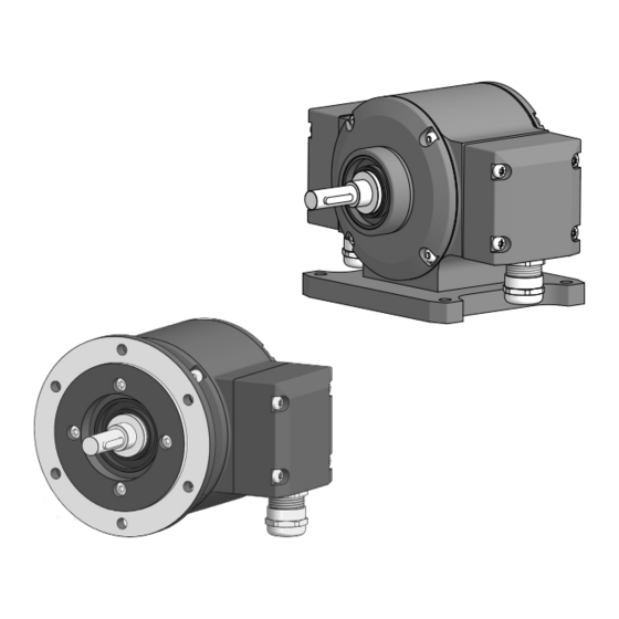
PREPARATION PREPARATION Scope of delivery EURO flange B10* Housing foot B3* Housing EURO flange B10* Radial terminal boxes* (see section Solid shaft with key [A] Incremental output 1 (option) Bearing shield [B] Incremental output 2 LED function indicators Housing foot B3* * Depending on version 8/32 MB261EN - 11196414, 21A1, Baumer_PMG10-Inc_EN_202103_MI_11196414... -
Page 9: 3�2 Required Accessory For Mounting (Not Included In Scope Of Delivery)
PREPARATION Required accessory for mounting (not included in scope of delivery) Connecting cables are required for the electrical connection� Details see section 6.2, page 25� Spring disk coupling K 35, available as accessory, see section 4.3, page 14� For mounting with EURO flange B10 Installation fitting, customized Fixing screw M6x16 mm for installation fitting, ISO 4017 For mounting with housing foot B3 Fixing screw M6x20 mm for housing foot, ISO 4017... -
Page 10: Mounting
MOUNTING EURO flange B10 4.1.1 Mounting the spring disk coupling to the device We recommend using the Baumer Hübner spring disk coupling K 35, see section 4.3, page 14, available as accessory� When other couplings are used pay attention to manufacturer‘s notes�... - Page 11 MOUNTING / EURO FLANGE B10 4.1.3 Mounting the spring disk coupling to the drive shaft 2�5 mm = 1.3 ±10 % Nm MB261EN - 11196414, 21A1, Baumer_PMG10-Inc_EN_202103_MI_11196414 11/32...
-
Page 12: 4�2 Mounting With Housing Foot B3
MOUNTING / HOUSING FOOT B3 Housing foot B3 4.2.1 Mounting the spring disk coupling to the device We recommend using the Baumer Hübner spring disk coupling K 35, see section 4.3, page 14, available as accessory� When other couplings are used pay attention to manufacturer‘s notes�... -
Page 13: 4�2�3 Mounting The Housing Foot And The Spring Disk Coupling To The Drive Shaft
MOUNTING / HOUSING FOOT B3 4.2.3 Mounting the housing foot and the spring disk coupling to the drive shaft 10 mm 2�5 mm = 1.3 ±10 % Nm 90 mm MB261EN - 11196414, 21A1, Baumer_PMG10-Inc_EN_202103_MI_11196414 13/32... -
Page 14: Coupling Is Used
Maximum permissible mounting tolerance when the Baumer Hübner K 35 spring disk coupling is used Devices with a solid shaft should be driven through the Baumer Hübner K 35 spring disk coupling (accessory), that can be pushed onto the shaft without axial loading�... -
Page 15: 4�4 Note When Using A Jaw-Type Coupling (For Example „Rotex®")
MOUNTING Note when using a jaw-type coupling (for example „ROTEX®“) Incorrect mounting of the jaw-type coupling can damage the device� Avoid blocking of both coupling halves (claws pressed together)� The device shaft must not subjected to direct axial shock� » Use a depth gauge to find and observe the correct distances (L, L1) for the device with EURO flange B10, see below. -
Page 16: Electrical Connection
ELECTRICAL CONNECTION / TERMINAL SIGNIFICANCE ELECTRICAL CONNECTION Terminal significance Voltage supply Ground Output signal channel 1 A− Output signal channel 1 inverted Output signal channel 2 (offset by 90° to channel 1) B− Output signal channel 2 inverted Zero pulse (reference signal) R− Zero pulse inverted System OK+ / error output nE−... -
Page 17: 5�3 Trigger Level
ELECTRICAL CONNECTION / TRIGGER LEVEL Trigger level Trigger level: TTL/HTL (Vin = Vout) High / Low: ≥2.5 V / ≤0.5 V (TTL) ≥Ub -3 V / ≤1.5 V (HTL) Transmission length: ≤550 m at 100 kHz (TTL) ≤350 m at 100 kHz (HTL) Output frequency: ≤600 kHz (TTL) ≤350 kHz (HTL) Programming interface (only PMG10P) Via connection SA and SB, encoder parameters such as the number of pulses for the in- cremental outputs 1 and 2 and/or the switch-off and switch-on speeds can be changed and read out�... -
Page 18: 5�6 Speed Switch (Option) - Switching Characteristics
ELECTRICAL CONNECTION / SWITCHING CHARACTERISTICS – SPEED SWITCH (OPTION) Switching characteristics – speed switch (option) The factory setting of the switching speed for the PMG10P is 6000 rpm� The PMG10 without programming interface is delivered with the individually ordered fixed swit- ching speed� Event State of the speed switch output During initialisation High resistance (overspeed) After initialisation and... -
Page 19: 5�7 Cable Connection
ELECTRICAL CONNECTION / CABLE CONNECTION Cable connection To ensure the specified protection of the device the correct cable diameter must be used� Connecting cables are not in scope of delivery and can be ordered separately as accesso- ry, see section 6.2, page 25� = 2���3 Nm TX 20 Terminal box cover Torx/slotted screw M4x32 mm Cable gland M20x1�5 mm for cable ø5���13 mm Cable shield... -
Page 20: 5�8 Assignment Connecting Terminal
ELECTRICAL CONNECTION / ASSIGNMENT CONNECTING TERMINAL Assignment connecting terminal Do not connect voltage supply to outputs! Danger of damage! Please, beware of possible voltage drop in long cable leads (inputs and out- puts)! 1x terminal box - View B (see dimensions) Incremental output II (connection reference -P) 1x terminal box - View B (see dimensions) Incremental output II + speed switch (connection reference -P) - Page 21 ELECTRICAL CONNECTION / ASSIGNMENT CONNECTING TERMINAL 2x terminal box - View B (see dimensions) Incremental output II (connection reference -M) 2x terminal box - View B (see dimensions) Incremental output II + speed switch (connection reference -M) 2x terminal box - View A (see dimensions) Incremental output I (connection reference -M) MB261EN - 11196414, 21A1, Baumer_PMG10-Inc_EN_202103_MI_11196414 21/32...
-
Page 22: Assignment Flange Connector M23
ELECTRICAL CONNECTION / ASSIGNMENT FLANGE CONNECTOR M23 Assignment flange connector M23 Do not connect voltage supply to outputs! Danger of damage! Please, beware of possible voltage drop in long cable leads (inputs and outputs)! 1x flange connector M23 - View B (see dimensions) Incremental output II (connection reference -H) Assignment 1x flange connector M23 - View B (see dimensions) - Page 23 ELECTRICAL CONNECTION / ASSIGNMENT FLANGE CONNECTOR M23 1x flange connector M23 - View B (see dimensions) Speed switch (connection reference -H) Assignment 2x flange connector M23 - View B / A (see dimensions) Incremental output II / Incremental output I (connection reference -L) View B/Inc.-outp.
- Page 24 ELECTRICAL CONNECTION / ASSIGNMENT FLANGE CONNECTOR M23 2x flange connector M23 - View B / A (see dimensions) Incremental output II + speed switch / Incremental output I (connection reference -L) View B/Inc.-outp. II + DSL View A/Inc.-outp. I 24/32 MB261EN - 11196414, 21A1, Baumer_PMG10-Inc_EN_202103_MI_11196414...
-
Page 25: Accessories
ACCESSORIES / Z-PA�SDL�1 WLAN ADAPTER: PROGRAMMING DEVICE FOR PMG10P ACCESSORIES Z-PA.SDL.1 WLAN adapter: Programming device for PMG10P The Z-PA�SDL�1 WLAN adapter is a programming device for programming and monitoring HMG10P/PMG10P series encoders� The following encoder parameters can be parameterized (depending on the version of the encoder): •... -
Page 26: Dimensions
DIMENSIONS / EURO FLANGE B12 AND TERMINAL BOX DIMENSIONS EURO flange B12 and terminal box 86.5 12.6 M20x1.5 ø7 (ø5...13) 86.5 86.5 12.6 M20x1.5 ø7 (ø5...13) 26/32 MB261EN - 11196414, 21A1, Baumer_PMG10-Inc_EN_202103_MI_11196414... -
Page 27: Euro Flange B10 And Flange Connector M23
DIMENSIONS / EURO FLANGE B10 AND FLANGE CONNECTOR M23 EURO flange B10 and flange connector M23 12.6 12.6 MB261EN - 11196414, 21A1, Baumer_PMG10-Inc_EN_202103_MI_11196414 27/32... -
Page 28: 7�3 Housing Foot B3 And Terminal Box
DIMENSIONS / HOUSING FOOT B3 AND TERMINAL BOX Housing foot B3 and terminal box 86.5 12.6 M20x1.5 ø7 (ø5...13) 86.5 86.5 12.6 M20x1.5 ø7 (ø5...13) 28/32 MB261EN - 11196414, 21A1, Baumer_PMG10-Inc_EN_202103_MI_11196414... -
Page 29: Dismounting
DISMOUNTING / EURO FLANGE B10 DISMOUNTING Risk of serious injuries Disconnect all electrical connections before dismounting� EURO flange B10 2�5 mm 10 mm 2�5 mm MB261EN - 11196414, 21A1, Baumer_PMG10-Inc_EN_202103_MI_11196414 29/32... -
Page 30: 8�2 Housing Foot B3
DISMOUNTING / HOUSING FOOT B3 Housing foot B3 10 mm 2�5 mm 2�5 mm 30/32 MB261EN - 11196414, 21A1, Baumer_PMG10-Inc_EN_202103_MI_11196414... -
Page 31: Technical Data
TECHNICAL DATA TECHNICAL DATA Technical data - electrical ratings Voltage supply: 4�75���30 VDC Short-circuit proof: Consumption w/o load: ≤100 mA Initializing time: ≤500 ms after power on Pulses per revolution: 1���131072 Phase shift: 90° ±20° Duty cycle: 40���60 % Reference signal: Zero pulse, width 90° Sensing method: Magnetic Output signals: A+, B+, R+, A−, B−, R−... -
Page 32: 9�3 Technical Data - Mechanical Design
Connection: Terminal box Flange connector M23 Weight approx�: 1�9 kg (depending on version) Baumer Hübner GmbH P�O� Box 12 69 43 · 10609 Berlin, Germany Phone: +49 (0)30/69003-0 · Fax: +49 (0)30/69003-104 info@baumerhuebner�com · www�baumer�com/motion 32/32 MB261EN - 11196414, 21A1, Baumer_PMG10-Inc_EN_202103_MI_11196414...