Baumer PMG10P Manuals
Manuals and User Guides for Baumer PMG10P. We have 9 Baumer PMG10P manuals available for free PDF download: Operating Manual, Mounting And Operating Instructions
Baumer PMG10P Operating Manual (44 pages)
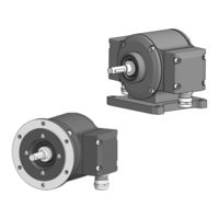
Absolute Encoder
Brand: Baumer
|
Category: Media Converter
|
Size: 2.9 MB
Table of Contents
Advertisement

Baumer PMG10P Operating Manual (44 pages)
Absolute Encoder
Brand: Baumer
|
Category: Media Converter
|
Size: 2.99 MB
Table of Contents

Baumer PMG10P Operating Manual (40 pages)
Absolute Encoder
Brand: Baumer
|
Category: Media Converter
|
Size: 2.98 MB
Table of Contents
Advertisement

Baumer PMG10P Operating Manual (40 pages)
Absolute Encoder
Brand: Baumer
|
Category: Media Converter
|
Size: 2.96 MB
Table of Contents

Baumer PMG10P Operating Manual (40 pages)
Absolute Encoder
Brand: Baumer
|
Category: Media Converter
|
Size: 2.25 MB
Table of Contents

Baumer PMG10P Operating Manual (36 pages)
Absolute Encoder
Brand: Baumer
|
Category: Media Converter
|
Size: 2.22 MB
Table of Contents
Baumer PMG10P Mounting And Operating Instructions (36 pages)
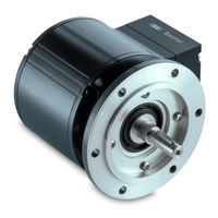
Absolute encoder SSI with magnetic sensing
Brand: Baumer
|
Category: Media Converter
|
Size: 2.97 MB
Table of Contents

Baumer PMG10P Mounting And Operating Instructions (32 pages)
Absolute encoder DeviceNet with magnetic sensing
Brand: Baumer
|
Category: Media Converter
|
Size: 2.84 MB
Table of Contents

Baumer PMG10P Mounting And Operating Instructions (32 pages)
Incremental encoder with magnetic sensing
Brand: Baumer
|
Category: Media Converter
|
Size: 2.99 MB
Table of Contents
Advertisement