Baumer HUBNER BERLIN PMG10 Operating Manual
Absolute encoder
Hide thumbs
Also See for HUBNER BERLIN PMG10:
- Mounting and operating instructions (32 pages) ,
- Mounting and operating instructions (32 pages)
Table of Contents
Advertisement
Quick Links
Advertisement
Chapters
Table of Contents

Related Manuals for Baumer HUBNER BERLIN PMG10


Summary of Contents for Baumer HUBNER BERLIN PMG10
- Page 1 Operating Manual PMG10 & PMG10P SSI EN-US Absolute Encoder...
-
Page 2: Table Of Contents
Attach coupling onto encoder shaft..................14 5.2.2 Mounting encoder onto drive shaft..................15 Maximum permitted tolerances for mounting errors when using the Baumer Hübner K 35 spring washer ..............................Notes when using a claw coupling (e.g. ROTEX®) ................18 6 Electrical installation........................... 19 Connections............................ - Page 3 Baumer Hübner List of contents LED activity indicator .......................... 23 Output switching behavior Speed switch (optional) ................23 Electrical connection with radial terminal boxes ................. 24 6.8.1 Connecting the supply cable ....................24 6.8.2 Pin assignment first terminal box ..................26 6.8.3...
-
Page 4: About This Document
In addition, the local occupational health and safety regulations and general safety regulations apply. The illustrations in this manual are examples only. Deviations are at the discretion of Baumer at all times. Warnings in this manual Warnings draw attention to potential personal injury or material damage. -
Page 5: Scope Of Delivery
SN: 7000063433231 Approvals and warranty UB= 9...30 VDC Declaration of conformity according to the prevailing country-specific directives. 2048 TTL (RS422) Default IP Address: 192.168.0.250 /24 MAC Adress: 9C:C9:50:00:A6:EE V1 | PMG10 & PMG10P SSI Operating Manual www.baumer.com Made in Germany... -
Page 6: Temperature Range For Operation And Storage
About this document Baumer Hübner We grant a 2-year warranty in line with the conditions of the German Electrical and Electronic Manufacturers' Association (ZVEI). INFO warranty seal Any breaking of the seal provided at the device will result in loss of warranty. -
Page 7: General Information
Used electrical and electronic devices may not be disposed of in household waste. The product contains valuable raw materials that can be recycled. There- fore dispose of this product at the appropriate collection point. For additional in- formation visit www.baumer.com. V1 | PMG10 & PMG10P SSI Operating Manual... -
Page 8: Transport And Storage
Transport and storage Baumer Hübner Transport and storage Transport NOTICE Material damage due to improper transport. a) Ensure maximum diligence when unloading the delivered packages as well as when trans- porting them inside the company. b) Note the information and symbols on the packaging. -
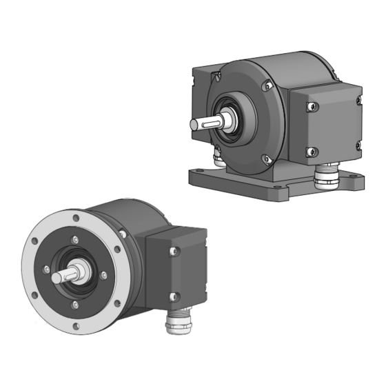
Page 9: Description
Baumer Hübner Description Description Rotary encoder Ill. 1: Description PMG10 Housing Cover LED activity indicator Housing base B3 (according to product variant) Radial flange connector: SSI, additional Radial flange connector: additional incre- incremental output 1 (optional), program- mental output 2 (option), speed switch... -
Page 10: Mounting Accessories (Not Included)
Description Baumer Hübner Mounting accessories (not included) Ill. 2: Mounting accessories Spring washer coupling K35, available as Mounting device, customer-specific (for accessory EURO flange B10 mount) Mounting screw M6x16 mm for attach- M6x20 mm screw for fastening the hous- ment device, ISO 4017 (for EURO flange... -
Page 11: Installation
Baumer recommends to use the Baumer Hübner K 35 spring disc coupling to connect the rotary encoder and the drive shaft of the following device. The Baumer Hübner K 35 spring disc cou- pling can be pushed onto the drive shaft without axial pressure. -
Page 12: Mounting Encoder Onto Drive Shaft
Instruction: a) Attach the coupling onto the encoder shaft according to the related mounting instructions. b) When using the K 35 spring washer of Baumer Hübner, consider the maximum permitted tolerances for mounting errors. c) Fasten the coupling at the specified torque (K 35: Mt = 1 Nm (plastic side), Mt = 1.3 ± 10% Nm (metal side)). -
Page 13: Ill. 4 Installing Encoder, Mounting Device And Coupling
Baumer Hübner Installation Ill. 4: Installing encoder, mounting device and coupling Drive shaft Mounting screw M6x16 mm for attach- ment device (ISO 4017) Attachment device (customized) Coupling Tools 2.5 mm 10 mm Instruction: a) Prior to installation, check the drive runout error and dimensions. -
Page 14: Mounting With Base B3
Baumer recommends to use the Baumer Hübner K 35 spring disc coupling to connect the rotary encoder and the drive shaft of the following device. The Baumer Hübner K 35 spring disc cou- pling can be pushed onto the drive shaft without axial pressure. -
Page 15: Mounting Encoder Onto Drive Shaft
Baumer Hübner Installation 5.2.2 Mounting encoder onto drive shaft DANGER Injuries caused by shaft rotation Hair and clothing may get caught in rotating shafts which may lead to serious personal injury. a) Make sure the device is idle. b) Before performing any work at the device, make sure power supply is and remains discon- nected. -
Page 16: Ill. 6 Mounting Encoder Onto Drive Shaft
Installation Baumer Hübner 90 mm Ill. 6: Mounting encoder onto drive shaft Drive shaft Coupling M6x20 mm screw for fastening the hous- Washer B6 for fastening the housing ing base (ISO 4017) base (DIN 137) Housing foot (according to product vari-... -
Page 17: Maximum Permitted Tolerances For Mounting Errors When Using The Baumer Hübner K 35 Spring
Fasten the coupling onto the shaft of the drive at a torque of 1.3 ±10 % Nm. Observe the remarks in the data sheet and the coupling assembly instructions. Maximum permitted tolerances for mounting errors when using the Baumer Hübner K 35 spring washer NOTICE Damage to the encoder ball bearings. -
Page 18: Notes When Using A Claw Coupling (E.g. Rotex®)
Installation Baumer Hübner Notes when using a claw coupling (e.g. ROTEX®) NOTICE Damage to the rotary encoder due to incorrect mounting of the claw coupling. Blocking of the two coupling halves (coupling claws lie face to face) can damage the rotary en- coder. -
Page 19: Electrical Installation
Baumer Hübner Electrical installation Electrical installation DANGER Injury by to secondary damage Encoder failure or incorrect signals may entail system control errors. a) Eliminate secondary encoder damage by the relevant safety precautions in the downstream electronics. NOTICE Sensor damage due to faulty power supply. -
Page 20: Connections
Electrical installation Baumer Hübner Connections Connection Description Operating voltage Ground connection Output signal channel 1 Output signal channel 1 inverted Output signal channel 2 (90° offset to channel 1) Output signal channel 2 inverted Zero pulse (reference signal) Zero pulse inverted... -
Page 21: Ssi Interface
Baumer Hübner Electrical installation SSI interface 6.2.1 Data transfer Clock Position Speed Data n-1...0 bit m-1...0 bit msb → lsb msb → lsb Clock frequency 100 kHz...2 MHz Monoflop time (t) 20 μs (intern) n, m Total of bits INFO No ring register operation present during ongoing triggering, i.e. -
Page 22: Output Signals Additional Incremental Output (Optional)
Electrical installation Baumer Hübner Output signals additional incremental output (optional) At positive rotating direction 90° Zero pulse+ Zero pulse- Ill. 9: Output signals with positive direction of rotation (zero pulse R+ and R- are only available at additional output II) Switching level additional output incremental (optional) -
Page 23: Led Activity Indicator
Baumer Hübner Electrical installation LED activity indicator green INC1 (additional incremental Undervoltage output 1) Overload Excess temperature INC2 (additional incremental Undervoltage output 2) Overload Excess temperature Status Internal error Speed Speed higher than switching Speed below switching speed speed (overspeed) Tab. 2: LED activity indicator... -
Page 24: Electrical Connection With Radial Terminal Boxes
Electrical installation Baumer Hübner Electrical connection with radial terminal boxes 6.8.1 Connecting the supply cable NOTICE Equipment damage due to dust or moisture Inappropriate cable diameters may entail ingress of dust or moisture. In this case, the protection class is no longer ensured causing device failure or malfunction. - Page 25 Baumer Hübner Electrical installation d) Insert the supply cables into the cable gland, let stick out approx. 50 mm of cable. e) Assign the supply cables to the terminals. f) Attach the cable gland to the terminal box. g) Mount the terminal box at the encoder. For doing so, tighten the screws with a torque of 2-3 V1 | PMG10 &...
-
Page 26: Pin Assignment First Terminal Box
Electrical installation Baumer Hübner 6.8.2 Pin assignment first terminal box NOTICE Operating voltage present at the outputs results in encoder damage. The encoder might be damaged by any operating voltage being present at the outputs. a) Make sure that no operating voltage is present at the outputs. -
Page 27: Assignment Of Connection Elements Second Terminal Box
Baumer Hübner Electrical installation 6.8.3 Assignment of connection elements second terminal box NOTICE Operating voltage present at the outputs results in encoder damage. The encoder might be damaged by any operating voltage being present at the outputs. a) Make sure that no operating voltage is present at the outputs. - Page 28 Electrical installation Baumer Hübner 27 mm 24 mm EMV ring Cable shield Second flange connector First flange connector Code Round connector M23 Supply cable (ø7-12 mm) Tools 24 mm 27 mm Crimping or soldering tool (depending on connector) Instruction: a) Push cable through inside the housing and insulate.
-
Page 29: Assignment First Flange Connector
Baumer Hübner Electrical installation 6.9.2 Assignment first flange connector NOTICE Operating voltage present at the outputs results in encoder damage. The encoder might be damaged by any operating voltage being present at the outputs. a) Make sure that no operating voltage is present at the outputs. -
Page 30: Assignment Second Flange Connector
Electrical installation Baumer Hübner 6.9.3 Assignment second flange connector NOTICE Operating voltage present at the outputs results in encoder damage. The encoder might be damaged by any operating voltage being present at the outputs. a) Make sure that no operating voltage is present at the outputs. -
Page 31: Z-Pa.sdl.1 Wlan Adapter: Programming Device For Hmg10P/Pmg10P
Baumer Hübner Electrical installation 6.10 Z-PA.SDL.1 WLAN adapter: Programming device for HMG10P/PMG10P INFO For detailed function descriptions refer to the WLAN adapter installation and operating instruc- tions. Ill. 15: Z-PA.SDL.1 WLAN adapter (ordering ref.: 11190106) The Z-PA.SDL.1 WLAN adapter is for programming and monitoring the HMG10P/PMG10P en- coder series. -
Page 32: Round Connector M23
Electrical installation Baumer Hübner 6.11.2 Round connector M23 INFO Round connectors are not included in the delivery but can be ordered individually to match the product variant (without supply cable). M23 round connector, 17-pin, soldered version, female contacts, counterclockwise (CCW), ordering designation: 11068551 Suitable for first flange connector. - Page 33 Baumer Hübner Electrical installation 62 mm L ±0.5% 80 ±5 mm ~15 mm ~15 mm ~5 mm View X 17-pin Core color Core cross-section MOVEMENT xMG10 White/Yellow 0,14 mm Black 0,14 mm White/Black 0,14 mm Brown 0,14 mm Brown/red 0,5 mm...
-
Page 34: For Encoders With Additional Incremental Output
Electrical installation Baumer Hübner 6.11.3.2 For encoders with additional incremental output Round connector M23, 17-pin with sensor cable HEK 17, 17 pins assigned (2x supply, 1x inter- nal shield, 10x signal, 4x data), female contacts, counterclockwise (CCW) Matching the first flange connector. -
Page 35: Disassembly
Baumer Hübner Disassembly Disassembly NOTICE Equipment damage due to mechanical impact Strong vibration may lead to overload by constraining force. a) Never apply force. If properly performed, all components can be uninstalled smoothly. b) Use only suitable tools to uninstall. -
Page 36: Uninstall When Using Euro Flange B10
Disassembly Baumer Hübner Uninstall when using EURO flange B10 7.1.1 Uninstall encoder from drive shaft DANGER Burns caused by heat The device heats up at high speeds. There is a risk of getting burned after use. a) Avoid overheating the device. - Page 37 Baumer Hübner Disassembly Tools 2.5 mm 10 mm Instruction: a) Disconnect all electrical connections. b) Loosen the the coupling on the drive shaft. Observe the notes in the data sheet and the coupling assembly instructions. c) Loosen the encoder from the drive's attachment device.
-
Page 38: Uninstall With Base B3
Disassembly Baumer Hübner Uninstall with base B3 7.2.1 Uninstall encoder from drive shaft DANGER Burns caused by heat The device heats up at high speeds. There is a risk of getting burned after use. a) Avoid overheating the device. b) Wear suitable protective gloves and clothing. - Page 39 Baumer Hübner Disassembly Tools 2.5 mm 10 mm Instruction: a) Disconnect all electrical connections. b) Loosen the the coupling on the drive shaft. Observe the notes in the data sheet and the coupling assembly instructions. c) Remove the encoder from the base.
-
Page 40: Technical Data
Technical data Baumer Hübner Technical data PMG10 Electrical Data Voltage supply Ub 4,75-30 V DC Short-circuit proof Operating current without load ≤ 100 mA Initializing time ≤ 500 ms after switch-on Sensing principle Magnetic Fieldbus interface Function Multiturn Steps per turn 1048576 / 20 Bit Number of turns 1048576 / 20 Bit... -
Page 41: Solid Shaft Encoder Dimensions With Euro Flange B10
Baumer Hübner Technical data PMG10 Rotor torque 1 kgcm Maximum permitted shaft load ≤ 450 N axial ≤ 650 N radial Materials Housing: aluminium alloy Shaft: stainless steel Operating temperature −40 ... +95 °C −40 ... +85 °C (speed switch with semiconduc- tor relay) Relative humidity 95 % not condensing... -
Page 42: With Radial Flange Connectors
Technical data Baumer Hübner 8.1.2 With radial flange connectors Ill. 19: Dimensions of the solid shaft encoder with EURO flange B10 with radial flange sockets (all in mm, unless specified otherwise) Solid shaft encoder dimensions with housing base B3 Ill. 20: Solid shaft encoder dimensions with housing base B3 (all in mm unless specified otherwise) Operating Manual PMG10 &... - Page 43 Baumer Hübner List of illustrations List of illustrations Ill. 1 Description PMG10..........................Ill. 2 Mounting accessories ......................... 10 Ill. 3 Attach coupling onto encoder shaft ....................11 Ill. 4 Installing encoder, mounting device and coupling ................13 Ill. 5 Attach coupling onto encoder shaft ....................14 Ill.
- Page 44 www.baumer.com/worldwide...