Table of Contents
Advertisement
Quick Links
Advertisement
Table of Contents

Related Manuals for Siemens Simatic ET 200pro FC


Summary of Contents for Siemens Simatic ET 200pro FC
- Page 3 ___________________ ET 200pro FC Foreword Fundamental safety ___________________ instructions ___________________ SIMATIC Description ___________________ Interfaces SIMATIC ET 200pro FC ET 200pro FC ___________________ Installation ___________________ Configuration / project engineering Operating Instructions ___________________ Commissioning (hardware) ___________________ Commissioning and optimization (software) ___________________ Series commissioning and...
- Page 4 Note the following: WARNING Siemens products may only be used for the applications described in the catalog and in the relevant technical documentation. If products and components from other manufacturers are used, these must be recommended or approved by Siemens. Proper transport, storage, installation, assembly, commissioning, operation and maintenance are required to ensure that the products operate safely and without any problems.
-
Page 5: Foreword
The online catalog and ordering system are available at: https://mall.automation.siemens.com/de/guest/guiRegionSelector.asp?lang=en/ Siemens offers various courses to get you started with the ET 200 and the SIMATIC S7 automation system. Information about our training courses is available on the Internet at: http://www.sitrain.com/index_en.html Information about FAQs (frequently asked questions) is available on the Internet at: http://www.automation.siemens.com/simatic (under "Support"... - Page 6 Foreword Experience required General knowledge in the field of automation engineering and drive technology is required to understand this manual. Recycling and disposal Thanks to the fact that it is low in contaminants, the ET 200 is recyclable. For environmentally-compliant recycling and disposal of your electronic waste, please contact a company certified for the disposal of electronic waste.
- Page 7 24-hour technical support is provided by four main centers worldwide. A&D Global service and support Online Service and support In the first instance for customer-support, contact should always be made with the regional (country based) sales/marketing/service organisations. http://support.automation.siemens.com ET 200pro FC Operating Instructions, 07/2016, A5E01100763B AC...
- Page 8 Tel: +86 (1064) 757 575 Fax: +86 (1064) 747 474 e-Mail: support.asia.automation@siemens.com Contact address Should any questions or problems arise while reading this manual, please contact Siemens at the following address: Siemens AG Automation & Drives A&D SD SPA PM4...
-
Page 9: Table Of Contents
Table of contents Foreword ..............................5 Fundamental safety instructions ......................13 General safety instructions ..................... 13 Safety instructions for electromagnetic fields (EMF) .............. 17 Handling electrostatic sensitive devices (ESD) ..............18 Industrial security ........................18 Residual risks of power drive systems ..................20 Description ............................ - Page 10 Table of contents Installation of the hardware information in SIMATIC Manager ..........64 5.2.1 Installation of a hardware support package (HSP) ..............64 5.2.2 Installation of a master device file (GSD) ................65 Configuring the communication ..................... 66 5.3.1 Generating a hardware configuration for PROFIBUS in the SIMATIC Manager ....66 5.3.2 Generating a hardware configuration for PROFINET in the SIMATIC Manager ....
- Page 11 Table of contents Alarm, fault, and system messages ..................... 147 Fault codes and interrupts ....................147 Diagnostics through LEDs ....................148 Diagnostics through STARTER .................... 152 Diagnostics through fieldbus ....................152 9.4.1 Diagnostics through the user program.................. 152 9.4.2 System diagnostics by means of standardized functions ............. 153 Device diagnostics ........................
- Page 12 Table of contents ET 200pro FC Operating Instructions, 07/2016, A5E01100763B AC...
-
Page 13: Fundamental Safety Instructions
Fundamental safety instructions General safety instructions DANGER Danger to life due to live parts and other energy sources Death or serious injury can result when live parts are touched. • Only work on electrical devices when you are qualified for this job. •... - Page 14 Fundamental safety instructions 1.1 General safety instructions WARNING Danger to life when live parts are touched on damaged devices Improper handling of devices can cause damage. For damaged devices, hazardous voltages can be present at the enclosure or at exposed components;...
- Page 15 Fundamental safety instructions 1.1 General safety instructions WARNING Danger to life due to fire spreading if housing is inadequate Fire and smoke development can cause severe personal injury or material damage. • Install devices without a protective housing in a metal control cabinet (or protect the device by another equivalent measure) in such a way that contact with fire is prevented.
- Page 16 Fundamental safety instructions 1.1 General safety instructions WARNING Danger of an accident occurring due to missing or illegible warning labels Missing or illegible warning labels can result in accidents involving death or serious injury. • Check that the warning labels are complete based on the documentation. •...
-
Page 17: Safety Instructions For Electromagnetic Fields (Emf)
Fundamental safety instructions 1.2 Safety instructions for electromagnetic fields (EMF) WARNING Danger to life or malfunctions of the machine as a result of incorrect or changed parameterization As a result of incorrect or changed parameterization, machines can malfunction, which in turn can lead to injuries or death. -
Page 18: Handling Electrostatic Sensitive Devices (Esd)
Siemens recommends strongly that you regularly check for product updates. For the secure operation of Siemens products and solutions, it is necessary to take suitable preventive action (e.g. cell protection concept) and integrate each component into a holistic, state-of-the-art industrial security concept. - Page 19 • Keep the software up to date. You will find relevant information and newsletters at this address (http://support.automation.siemens.com). • Incorporate the automation and drive components into a holistic, state-of-the-art industrial security concept for the installation or machine.
-
Page 20: Residual Risks Of Power Drive Systems
Fundamental safety instructions 1.5 Residual risks of power drive systems Residual risks of power drive systems When assessing the machine- or system-related risk in accordance with the respective local regulations (e.g., EC Machinery Directive), the machine manufacturer or system installer must take into account the following residual risks emanating from the control and drive components of a drive system: 1. -
Page 21: Description
The commissioning software STARTER is used for commissioning. It can be downloaded from the Siemens homepage or ordered on a data carrier. It parameterizes the frequency converter through a fieldbus or a point-to-point connection. You have the option of reading the parameters for operating the frequency converter from the EEPROM of the frequency converter or from a Micro Memory Card (MMC) that is inserted in the frequency converter. - Page 22 Description 2.1 The frequency converter ● No braking resistor required ● Robust EMC design ● Can be configured for a wide range of applications ● Powerfail-proof storage of parameter settings on either EEPROM or MMC ● Control and diagnostics using a higher-level controller (e.g. SIMATIC S7) ●...
- Page 23 Description 2.1 The frequency converter Function modules ● Vector control (speed and torque control) without encoder ● V/f control with different characteristics Protective functions ● Motor protection functions ● Frequency converter protection functions ● System protection functions Interfaces ● PROFIBUS or PROFINET through backplane bus ●...
-
Page 24: Components For Assembling A Frequency Converter
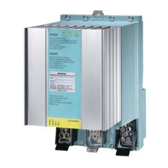
Description 2.2 Components for assembling a frequency converter Components for assembling a frequency converter General information The following section provides an overview of configuration options for the frequency converters in the ET 200pro distributed I/O system. Other general information on the ET 200pro distributed I/O system can be found in the manual entitled "ET 200pro Distributed I/O System". - Page 25 Description 2.2 Components for assembling a frequency converter Table 2- 1 Components of the standard frequency converter Illustration Components Function Rack, wide The ET 200pro bus modules, onto which the electronic modules are screwed, must be mounted on the rack. Lengths: 0.5 m, 1 m Interface module for The interface module interconnects the ET 200pro with the DP master and...
- Page 26 Description 2.2 Components for assembling a frequency converter Fail-safe frequency converter Image 2-2 Fail-safe frequency converter with F-RSM Table 2- 2 Components of the fail-safe frequency converter with F-RSM Illustration Components Function Rack, wide The ET 200pro bus modules, onto which the electronic modules are screwed, must be mounted on the rack.
- Page 27 Description 2.2 Components for assembling a frequency converter Illustration Components Function Connection modules for inter- The connection modules are mounted on the interface modules. They are face modules used to connect PROFIBUS DP, the electronics/encoder supply and the load voltage supply. Available connection modules: Direct connection: •...
- Page 28 Description 2.2 Components for assembling a frequency converter Image 2-3 Fail-safe frequency converter with F-Switch Table 2- 3 Components of the fail-safe frequency converter with F-Switch Illustration Components Function Rack, wide The ET 200pro bus modules, onto which the electronic modules are screwed, must be mounted on the rack.
- Page 29 Description 2.2 Components for assembling a frequency converter Illustration Components Function Not illus- Interface module for The interface module interconnects the ET 200pro with the IO controller and trated PROFINET IO, with bus mod- prepares the data for the electronic modules. The interface module and connection module are shipped as a compact unit.
-
Page 30: Limit / Maximum Expansion Of The Et 200Pro Modules That Can Be Connected
Description 2.3 Limit / maximum expansion of the ET 200pro modules that can be connected Limit / maximum expansion of the ET 200pro modules that can be connected Maximum expansion for each IM 154 interface module When configuring the system, please note the following: ●... -
Page 31: Overview Of The Leds
2.4 Overview of the LEDs Overview of the LEDs Status display through LEDs The SIMATIC ET 200pro FC frequency converters have a number of functions and statuses that can be displayed by means of LEDs. Standard frequency converter Fail-safe frequency converter... - Page 32 Description 2.4 Overview of the LEDs Description of the LEDs LEDs Description System failure (SF) The "System failure" LED indicates a general system error in either the software or hardware. Ready (RY) The Ready LED indicates whether the converter is ready; a control word is sent for this purpose.
-
Page 33: Interfaces
Interfaces Communication interfaces Overview The frequency converter has 3 communication interfaces. These are: ● An optical interface for commissioning the frequency converter using a PC and the RS232 interface ● A fieldbus connection Through the ET 200pro backplane bus for communicating with a higher-level control ●... -
Page 34: Optical Interface
Interfaces 3.1 Communication interfaces 3.1.1 Optical interface Description The ET 200pro FC frequency converter has a serial optical communication interface with USS protocol for commissioning using the STARTER commissioning software on a PC. RS232/optical conversion is performed in the cable between the PC and the frequency converter. -
Page 35: Mmc Interface (Micro Memory Card)
Interfaces 3.1 Communication interfaces 3.1.3 MMC interface (Micro Memory Card) Description The MMC interface can be used to back up frequency converter parameters on an external MMC and, if required, download them back onto the frequency converter. Possible fields of application for the MMC The MMC can be used as a parameter memory: ●... -
Page 36: Ptc/Kty84 Interface
Interfaces 3.2 PTC/KTY84 interface PTC/KTY84 interface The PTC/KTY84 interface can be optionally used. Description The connection for a PTC/KTY84 sensor to monitor the motor temperature is integrated in the motor plug connector. WARNING Electric shock when touching connection pins (male connections) in the motor terminal box The connections for the temperature sensor and the motor holding brake are switched to the minus potential of the DC link. -
Page 37: Interface To The Motor Holding Brake
Interfaces 3.3 Interface to the motor holding brake Interface to the motor holding brake Description A motor holding brake can be controlled using the ET 200pro FC. The electrical connection between the frequency converter and the brake is established by plugging the motor cable into the frequency converter. - Page 38 Interfaces 3.3 Interface to the motor holding brake ET 200pro FC Operating Instructions, 07/2016, A5E01100763B AC...
-
Page 39: Installation
Installation Prerequisites and maximum expansion Maximum mechanical expansion The maximum expansion of an ET 200pro is reached when one of the rules outlined below applies: Table 4- 1 Maximum mechanical expansion Features Rule Number of modules max. 16 electronic modules Width of ET 200pro max. -
Page 40: Mounting The Racks
Installation 4.2 Mounting the racks Mounting the racks The frequency converter is mounted on the wide rack. The following versions are possible: ● Rack, wide ● Rack, compact-wide ET 200pro FC Operating Instructions, 07/2016, A5E01100763B AC... - Page 41 Installation 4.2 Mounting the racks Dimensions Image 4-1 Dimensional drawing of compact-wide rack ET 200pro FC Operating Instructions, 07/2016, A5E01100763B AC...
- Page 42 Installation 4.2 Mounting the racks Image 4-2 Dimensional drawing of wide module rack ET 200pro FC Operating Instructions, 07/2016, A5E01100763B AC...
- Page 43 Installation 4.2 Mounting the racks Tools required ● Wrench or screwdriver, matching the selected fixing screws. ● Stripping tool and crimp tool for the grounding cable. Accessories required Table 4- 3 Rack and grounding cable For... you can use ... Explanation Outer fixing screws M8 cylindrical head screw according to...
-
Page 44: Mounting The Interface Module
Installation 4.3 Mounting the interface module Mounting the interface module The interface module connects ET 200pro to PROFIBUS DP/ PROFINET IO and supplies power to the electronic modules. Requirements ● Interface module for PROFIBUS DP – The terminating module is removed from the interface module. –... - Page 45 Installation 4.3 Mounting the interface module Procedure 1. Snap-mount the Interface module onto the rack, then slide it into the correct position 2. Screw-mount the Interface module onto the rack. Interface module for PROFIBUS DP (without connection module): 2 recessed head screws on the front: top and bottom, tightening torque 1.5 N/m Interface module for PROFINET IO: All recessed head screws on the front: top and bottom, tightening torque 1.5 N/m Image 4-4...
-
Page 46: Mounting The Bus Module
Installation 4.4 Mounting the bus module Mounting the bus module The bus module connects the frequency converter to the ET 200pro backplane bus. Requirements ● The interface module is mounted on the rack. ● Additional bus modules can be mounted next to the interface module Procedure 1. - Page 47 Installation 4.4 Mounting the bus module Image 4-5 Mounting the bus module for frequency converters ① Interface module ② Bus module 155 mm ET 200pro FC Operating Instructions, 07/2016, A5E01100763B AC...
-
Page 48: Mounting The Terminating Module
Installation 4.5 Mounting the terminating module Mounting the terminating module The ET 200pro station must be terminated with the terminating module. Requirements ● All bus modules are mounted on the rack. Required tools Cross-tip screwdriver, size 2 ET 200pro FC Operating Instructions, 07/2016, A5E01100763B AC... - Page 49 Installation 4.5 Mounting the terminating module Procedure 1. Mount the terminating module onto the rack. 2. Slide the terminating module to the left up against the last bus module. Note Do not screw the terminating module to the rack (2 recessed head screws at the front, torque 1.5 Nm) until all the bus modules are mounted and screwed in place.
-
Page 50: Mounting The Connection Module For Im154
Installation 4.6 Mounting the connection module for IM154 Mounting the connection module for IM154 There are various connection modules with different connection methods for IM 154 ● CM IM DP ECOFAST Cu ● CM IP DP M12, 7/8" ● CM IM DP Direct. Requirements The interface module must be mounted. - Page 51 Installation 4.6 Mounting the connection module for IM154 Procedure 1. Make the settings depending on the connection module and establish the internal connections The settings and connections of all communication modules are described in the manual "ET 200pro Distributed I/O Devices" 2.
-
Page 52: Mounting The Frequency Converters
Installation 4.7 Mounting the frequency converters Mounting the frequency converters The frequency converter is unpacked and screwed onto the bus module using 8 screws. Note When removing the device from the packaging, be sure not to touch or damage the rear plug. - Page 53 Installation 4.7 Mounting the frequency converters Requirements The bus module for the frequency converter and all the modules to the left are mounted. Tools required Cross-head screwdriver, size 2. Procedure 1. Plug the frequency converter into the bus module so that the two domes on the rear engage in the guide holes of the bus module.
-
Page 54: Wiring In The Et 200Pro System
Installation 4.8 Wiring in the ET 200pro system Wiring in the ET 200pro system Communication and auxiliary voltages are routed with standard connectors through the interface module (or power modules) and the backplane bus to the frequency converter and do not have to be considered here. The power unit of the frequency converter is designed for direct operation on TN and TT line supply systems with a grounded neutral conductor with a rated voltage of 3 AC 400 V. - Page 55 Installation 4.8 Wiring in the ET 200pro system Required tools If you use prefabricated standard cables, no tools will be needed on the frequency converter side. You can adapt the motor side to address your needs. The following tools will be required if you want to assemble the cables yourself.
- Page 56 Installation 4.8 Wiring in the ET 200pro system Image 4-11 Wiring the frequency converter in the ET 200pro system ET 200pro FC Operating Instructions, 07/2016, A5E01100763B AC...
- Page 57 Installation 4.8 Wiring in the ET 200pro system WARNING Electric shock when touching connection pins (male connections) in the motor terminal box The connections for the temperature sensor and the motor holding brake are switched to the minus potential of the DC link. Electric shock when touching the connection pins (male connections) in the motor terminal box can result in death.
- Page 58 Installation 4.8 Wiring in the ET 200pro system Motor cable Motor cables up to 10 m long are available under the following order designation: ● 6ES7194-1LA01-0AA0 (1.5 m) ● 6ES7194-1LB01-0AA0 (3.0 m) ● 6ES7194-1LC01-0AA0 (5.0 m) ● 6ES7194-1LD01-0AA0 (10.0 m). Longer lengths up to 15 m can be obtained from our service providers.
-
Page 59: Mounting A Fail-Safe Frequency Converter
Installation 4.9 Mounting a fail-safe frequency converter Mounting a fail-safe frequency converter Fail-safe applications are configured basically the same as standard applications but with the following differences: ● Mounted to the left of the frequency converter must be a module through which the safety functions of the frequency converter can be actuated, for example: –... -
Page 60: Mounting The Bus Module For F-Rsm And Mounting The Repair Switch Module
Installation 4.9 Mounting a fail-safe frequency converter 4.9.1 Mounting the bus module for F-RSM and mounting the repair switch module The Safety Local function of the F-RSM, its use, control elements and connections are SIMATIC ET 200pro Motor Starters described in detail in the manual Therefore, only the most important points concerning its use with a frequency converter will be covered here. -
Page 61: Mounting The Module For The F-Switch
Installation 4.9 Mounting a fail-safe frequency converter 4.9.2 Mounting the module for the F-Switch The function, use, control elements and connections of the F-Switch are described in detail ET 200pro Distributed I/O Devices - Fail-safe Modules in the manual Therefore, only the most important points concerning its use with a frequency converter will be covered here. - Page 62 Installation 4.9 Mounting a fail-safe frequency converter ET 200pro FC Operating Instructions, 07/2016, A5E01100763B AC...
-
Page 63: Configuration / Project Engineering
Configuration / project engineering Integrating ET 200 frequency converters into automation systems with STEP 7 General information on STEP 7 STEP 7 is the basic package for configuring and programming SIMATIC automation systems. It is part of the SIMATIC industry software. The STEP 7 basic package is available in several versions. -
Page 64: Installation Of The Hardware Information In Simatic Manager
Configuration / project engineering 5.2 Installation of the hardware information in SIMATIC Manager Installation of the hardware information in SIMATIC Manager 5.2.1 Installation of a hardware support package (HSP) The HSP (hardware support package) file defines the system environment of an ET 200pro station. -
Page 65: Installation Of A Master Device File (Gsd)
Configuration / project engineering 5.2 Installation of the hardware information in SIMATIC Manager 5.2.2 Installation of a master device file (GSD) The device description for the frequency converter is declared to HW Config in STEP 7 by installing the GSD (master device file) for use with PROFIBUS and the GSDML for use with PROFINET. -
Page 66: Configuring The Communication
Configuration / project engineering 5.3 Configuring the communication Configuring the communication The frequency converter is operated by means of PROFIdrive profile. Table 5- 1 Operation with standard telegram 1 Usable PLC Any PLC Possible fieldbus PROFIBUS DP or PROFINET IO Required blocks None Communication between frequency converter and STARTER com-... - Page 67 Configuration / project engineering 5.3 Configuring the communication Parameterizing the PROFIBUS DP interface in SIMATIC S7 The PROFIBUS DP interface is parameterized when configuring the hardware. When a CPU with integrated DP interface or a DP communication processor is selected from the hardware catalog, a PROFIBUS DP system is provided in the hardware configuration.
- Page 68 Configuration / project engineering 5.3 Configuring the communication Image 5-3 Allocating the slave address at the PROFIBUS DP The configuration should now appear as follows: Image 5-4 Configuration ET 200pro FC Operating Instructions, 07/2016, A5E01100763B AC...
- Page 69 Configuration / project engineering 5.3 Configuring the communication Inserting a converter in an ET 200pro slot From the hardware catalog select "FC 1.1/1.5 kW; standard telegram 1" and pull it onto the slot. Image 5-5 Selecting the frequency converter Image 5-6 Frequency converter in slot With this selection the user specifies which frequency converter will be used (standard or fail-safe).
- Page 70 Configuration / project engineering 5.3 Configuring the communication Address/ID Setting an address in the I/O map The start address configured here is accepted in the user program as the "LADDR" input parameter for the blocks in the user program. Image 5-7 Setting the address in the I/O map Note The input and output address area of the frequency converter must be the same.
- Page 71 Configuration / project engineering 5.3 Configuring the communication Parameter The application ID provides a unique means of identification and is assigned by the user. Note If the same application ID is entered for several frequency converters, they can be used interchangeably.
- Page 72 Configuration / project engineering 5.3 Configuring the communication Points to note when using the PROFIdrive profile The alarm mode of the ET 200pro slave must be set to DPV1. ● Double-click the ET 200pro system ● Select the "Operating parameters" tab Image 5-9 Operating parameters ●...
-
Page 73: Generating A Hardware Configuration For Profinet In The Simatic Manager
Configuration / project engineering 5.3 Configuring the communication Image 5-10 Setting the device-specific parameters 5.3.2 Generating a hardware configuration for PROFINET in the SIMATIC Manager Description The following example of an ET 200pro FC frequency converter with an "IM 154-4 PN HF" interface module will be used to demonstrate how to generate a PROFINET configuration with HW Config in the SIMATIC Manager. - Page 74 Configuration / project engineering 5.3 Configuring the communication Inserting the IO controller using the context menu of the CPU PROFINET IO interface Image 5-11 Inserting an IO Controller After the PROFINET IO system was inserted, a network must be created for it. In the context menu of the PN-IO click on "Object properties".
- Page 75 Configuration / project engineering 5.3 Configuring the communication Inserting the ET 200pro system in the IO Controller Image 5-13 Selecting the ET 200pro from the hardware catalog Specifying the device name In the PROFINET version, the address of the I/O devices is assigned via their device names. To do this, click the ET 200pro station in the HW Config tool to open its properties.
- Page 76 Configuration / project engineering 5.3 Configuring the communication The ET 200pro must then declare the name that has been selected. This can be performed in 2 different ways: ● Direct route --> The NameOfStation is written via PROFINET to the MMC of the IM in the ET 200pro: The prerequisite for this is a PC with PG functionality, which can establish an Ethernet connection with the ET 200pro.
- Page 77 Configuration / project engineering 5.3 Configuring the communication Inserting a converter in an ET 200pro slot From the hardware catalog select "FC 1.1/1.5 kW; standard telegram 1" and pull it onto the slot. Image 5-16 Selecting the frequency converter Image 5-17 Frequency converter in slot Settings for the frequency converter Double-clicking the frequency converter opens the property view with the following tabs:...
- Page 78 Configuration / project engineering 5.3 Configuring the communication Address/ID Setting an address in the I/O map The start address configured here is accepted in the user program as the "LADDR" input parameter for the blocks in the user program. Image 5-18 Setting the address in the I/O map Note The input and output address area of the frequency converter must be the same.
- Page 79 Configuration / project engineering 5.3 Configuring the communication Image 5-19 Parameter ET 200pro FC Operating Instructions, 07/2016, A5E01100763B AC...
- Page 80 Configuration / project engineering 5.3 Configuring the communication Points to note when using the PROFIdrive profile The alarm mode of the ET 200pro slave must be set to DPV1. ● Double-click the ET 200pro system ● Select the "Operating parameters" tab Image 5-20 Operating parameters ●...
-
Page 81: Creating A Fail-Safe Configuration In Simatic Manager
● S7 Distributed Safety V5.4 or higher (F Configuration Pack V5.5 SP1 or higher) ● S7 F systems V5.2 SP2 or higher The F Configuration Pack can be downloaded from the Internet (www.siemens.com/automation/service&support). ET 200pro FC Operating Instructions, 07/2016, A5E01100763B AC... - Page 82 Configuration / project engineering 5.3 Configuring the communication Procedure Once the IM154-2 HF has been positioned and parameterized in the master system, a module that can control the safety functions of the frequency converter using switch-off signals in the backplane bus is positioned to the left of the frequency converter. A fail-safe module (F-Switch or F-RSM) is then plugged in.
- Page 83 Configuration / project engineering 5.3 Configuring the communication Image 5-22 Defining the start address Group diagnostics can be activated or deactivated. Image 5-23 Specifying the diagnostics properties ET 200pro FC Operating Instructions, 07/2016, A5E01100763B AC...
- Page 84 Configuration / project engineering 5.3 Configuring the communication You can use drag-and-drop to position the fail-safe frequency converter to the right of the F- Switch or F-RSM module. The configuration sequence is identical to the one used when generating a PROFIBUS configuration in the SIMATIC Manager. Image 5-24 Configuring a frequency converter in a Safety Local environment Parameterizing module properties...
-
Page 85: Commissioning (Hardware)
Commissioning (hardware) Introduction Hardware commissioning involves the ET 200pro station and the drive components. The following procedure describes by way of example the commissioning of a minimum configuration on PROFIBUS DP, with an S7 controller as the master and STARTER software directly on the optical interface of the frequency converter. - Page 86 Commissioning (hardware) 6.1 Startup of ET 200pro Mode of operation The illustration below represents the startup routine of the ET 200pro with a frequency converter. Image 6-1 Starting up an ET 200pro with frequency converter Note The SF LED on the S7 will not necessarily light up if an error occurs on the ET 200pro FC. The S7 receives notification of an error only if diagnostic messages are enabled in the converter.
-
Page 87: Creating A Drive Configuration With Starter
Commissioning (hardware) 6.2 Creating a drive configuration with STARTER Creating a drive configuration with STARTER Procedure ● Connect STARTER to the to the RS232 interface of the frequency converter. ● Create a drive configuration and check the motor data. Checking the motor terminal box (IEC/NEMA motor) For commissioning to be successful, it is important that the interconnection in the motor terminal box (see image below) corresponds to the entry for the rated motor voltage (P0304)/rated motor current (P0305). - Page 88 Commissioning (hardware) 6.2 Creating a drive configuration with STARTER e.g.: Voltage of 230 V YY (low)/460 V Y (high) Voltage Connected to one another Circuit -T6-T7 ∆ ∆ High ∆ Entering the type plate data The following should be noted when entering the type plate data/ESB data: ●...
-
Page 89: Commissioning And Optimization (Software)
Commissioning and optimization (software) Commissioning sequence The sequence in which the software of a frequency converter in an ET 200 station is commissioned depends on how complex the drive application is, and on the automation structure. The basic drive functions and the higher-level controller are commissioned first and are then specialized, optimized and the drive application generated. - Page 90 Commissioning and optimization (software) 7.1 Commissioning sequence Table 7- 1 First commissioning and optimization Steps Description Tool 1 Commissioning and optimiz- Basic parameterization has already been carried out when STARTER at the ing the frequency convert- commissioning the hardware (quick commissioning). RS232 interface er/motor combination The motor type plate data and the frequency converter factory...
-
Page 91: Commissioning And Optimization Of The Frequency Converter And Motor Combination
Commissioning and optimization (software) 7.2 Commissioning and optimization of the frequency converter and motor combination Commissioning and optimization of the frequency converter and motor combination Description If there is still no matching parameter set for the drive, then quick commissioning including a motor data identification routine must be carried out - both for the closed-loop vector control and the V/f control. - Page 92 Commissioning and optimization (software) 7.2 Commissioning and optimization of the frequency converter and motor combination STARTER projects STARTER can be used to either create a new project or open an existing one. To create a new project in STARTER, any of the following procedures can be used: ●...
-
Page 93: Calculating The Motor And Controller Data
Commissioning and optimization (software) 7.2 Commissioning and optimization of the frequency converter and motor combination 7.2.2 Calculating the motor and controller data The internal motor and controller data are calculated using the parameter P0340, or indirectly with the help of the parameter P3900 or P1910. The function of the parameter P0340 can be used, for example, if the data of the replacement circuit or the values of the moments of inertia are known. - Page 94 Commissioning and optimization (software) 7.2 Commissioning and optimization of the frequency converter and motor combination The rating plate data represents the initialization values for the identification. This is the reason that it is necessary to have the correct input from the rating plate data when determining the data specified above.
- Page 95 Commissioning and optimization (software) 7.2 Commissioning and optimization of the frequency converter and motor combination identification time depends on the motor and increases with its size (this takes approx. 4 min. for a 200 kW motor). The motor data identification routine must be carried-out with the motor in the cold condition so that the motor resistance values saved can be assigned to the parameter of the ambient temperature P0625.
- Page 96 Commissioning and optimization (software) 7.2 Commissioning and optimization of the frequency converter and motor combination current P0320 entered. The motor data identification routine should then be re-started by calling P1900 = 2 or P1900 = 3. A step-by-step description is given in section "Quick Commissioning". Parameter settings WARNING The motor data identification routine MUST not be used for loads which are potentially...
-
Page 97: Commissioning And Optimization Of The Drive Application
Commissioning and optimization (software) 7.3 Commissioning and optimization of the drive application Commissioning and optimization of the drive application After the motor and converter combination is commissioned by quick commissioning, parameters must be adapted and set to suit the requirements of the specific application. Note According to the factory setting, parameter changes are saved in the volatile memory (RAM) of the converter. - Page 98 Commissioning and optimization (software) 7.3 Commissioning and optimization of the drive application Temperature encoder Parameters Description (parameters and factory settings in bold) Setting P0601 = 0 Motor temperature encoder 0: No encoder (→ P0610) P0601 = … 1: PTC thermistor (→ P0604) 2: KTY84 (→...
- Page 99 Commissioning and optimization (software) 7.3 Commissioning and optimization of the drive application JOG frequency Parameter Description Setting P1057 = 1 JOG Enable P1057 = 0 JOG-function disabled P1057 = 1 JOG-function enabled (default) P1058 = 5 JOG frequency right Frequency in Hz when the motor is being jogged in the clockwise direction. P1059 = 5 JOG frequency left Frequency in Hz when the motor is being jogged in the counter-clockwise direction.
- Page 100 Commissioning and optimization (software) 7.3 Commissioning and optimization of the drive application Ramp times Parameter Description Setting P1120 = 10 Ramp-up time Enter the acceleration time in seconds. P1121 = 10 Ramp-down time Enter the deceleration time in seconds. Rounding Parameter Description Setting...
- Page 101 Commissioning and optimization (software) 7.3 Commissioning and optimization of the drive application Parameters which must be set before ending the application settings The following parameters must be configured for every application. Parameters Description (parameter name and factory setting (if non-variable) in bold print) Setting P1800 = 4 Pulse frequency (kHz)
-
Page 102: Commissioning Of Communication Between The S7 Cpu And The Frequency Converter
Commissioning and optimization (software) 7.4 Commissioning of communication between the S7 CPU and the frequency converter Commissioning of communication between the S7 CPU and the frequency converter 7.4.1 Parameter settings for communication The frequency converter is operated by means of PROFIdrive profile. Table 7- 5 Standard telegram 1 Telegram... - Page 103 Commissioning and optimization (software) 7.4 Commissioning of communication between the S7 CPU and the frequency converter Table 7- 7 Parameters for flexibly interconnecting process data in the PROFIdrive profile Telegram PZD1 PZD2 STW/ZSW HSW/HIW Connection values for setpoints, master to converter r2050.00 r2050.01 Connection parameters for actual values, converter to master...
-
Page 104: Process Data Transfer In The Profidrive Profile
Commissioning and optimization (software) 7.4 Commissioning of communication between the S7 CPU and the frequency converter P0927 parameter change source Description Value Fieldbus 0: No 1: Yes Local interface 0: No 1: Yes The factory setting for all bits is 1, i.e., the parameters can be changed from all sources. 7.4.2 Process data transfer in the PROFIdrive profile 7.4.2.1... - Page 105 Commissioning and optimization (software) 7.4 Commissioning of communication between the S7 CPU and the frequency converter Value Meaning Remarks Enable setpoint The value selected on the ramp function generator input is enabled. Inhibit setpoint The value selected on the ramp function generator input is set to 0 (zero).
- Page 106 Commissioning and optimization (software) 7.4 Commissioning of communication between the S7 CPU and the frequency converter Value Meaning Remarks Fault present Drive is faulty. A fault is present in the drive; it is, there- fore, not operating and will switch back to the "Begin start interlock"...
-
Page 107: Examples
Commissioning and optimization (software) 7.4 Commissioning of communication between the S7 CPU and the frequency converter 7.4.2.2 Examples Writing PROFIdrive process data In this example, the control word STW1 and the setpoint frequency are written in PROFIdrive mode. The inputs E0.0 and E0.6 are linked to the Start/Stop bit or to the Acknowledge Fault bit of the control word STW1. - Page 108 Commissioning and optimization (software) 7.4 Commissioning of communication between the S7 CPU and the frequency converter Image 7-3 Writing PROFIdrive process data Reading PROFIdrive process data In this example, status word 1 and the instantaneous frequency are read in PROFIdrive mode.
-
Page 109: Parameter Transfer In The Profidrive Profile
PROFIdrive profile, V4.0 (with data block 47 (DS47)). ● Acyclic data exchange with the help of a SIEMENS startup tool (master of Class 2 or supervisor) (e.g. STARTER). The startup tool can acyclically access parameters and process data in the frequency converter. - Page 110 Commissioning and optimization (software) 7.4 Commissioning of communication between the S7 CPU and the frequency converter Properties of the parameter channel ● One 16-bit address for each parameter number and subindex. ● Transfer of different parameters in one access (multiple request). ●...
- Page 111 Commissioning and optimization (software) 7.4 Commissioning of communication between the S7 CPU and the frequency converter Table 7- 10 Parameter request Word Byte Byte Request header Request reference Request ID Drive object ID Qty Parameters 1. Parameter address Attribute Qty of elements Parameter number (PNU) Subindex …...
- Page 112 Commissioning and optimization (software) 7.4 Commissioning of communication between the S7 CPU and the frequency converter Description of the fields for a parameter request and response Table 7- 12 Description of the fields for parameter requests Field Data type Values Remark Request reference Unsigned 8 0x01 …...
- Page 113 Commissioning and optimization (software) 7.4 Commissioning of communication between the S7 CPU and the frequency converter Field Data type Values Remark Format Unsigned 8 0x02 Data type: integer 8 0x03 Data type: integer 16 0x04 Data type: integer 32 0x05 Data type: unsigned 8 0x06 Data type: unsigned 16...
- Page 114 Commissioning and optimization (software) 7.4 Commissioning of communication between the S7 CPU and the frequency converter Table 7- 13 Description of the fields for parameter requests Field Data type Values Remark Request ID Unsigned 8 0x01 Read request (+) Request positive, status ok 0x02 Write request (+)
- Page 115 Commissioning and optimization (software) 7.4 Commissioning of communication between the S7 CPU and the frequency converter Error Meaning Remark Additional value inf. 0x06 Invalid "Set" action (only reset is Attempt to modify with a value unequal Subindex allowed) 0 in a situation where this is not al- lowed.
-
Page 116: Examples
Commissioning and optimization (software) 7.4 Commissioning of communication between the S7 CPU and the frequency converter 7.4.3.2 Examples Writing PROFIdrive parameters In order to make use of DS47, a data block first needs to be created in Simatic Manager. This implements the data set structure using the parameter request table as a template. In this example, a data set is stored in DB47 for the purpose of changing P1082 (maximum frequency). - Page 117 Commissioning and optimization (software) 7.4 Commissioning of communication between the S7 CPU and the frequency converter Image 7-7 Request processing in OB1 Once the parameter request has been executed successfully, the request header (defined in DB47) must be mirrored in DB1 (requestID does not indicate any errors). To view the data currently stored in DB1, open DB1 in Simatic Manager and click the glasses icon.
- Page 118 Commissioning and optimization (software) 7.4 Commissioning of communication between the S7 CPU and the frequency converter The parameter response table provides information about the structure of the reply data set. Reading PROFIdrive parameters (example) In order to make use of DS47, a data block first needs to be created in SIMATIC Manager. The structure of the data set will then be implemented in it.
- Page 119 Commissioning and optimization (software) 7.4 Commissioning of communication between the S7 CPU and the frequency converter ET 200pro FC Operating Instructions, 07/2016, A5E01100763B AC...
- Page 120 Commissioning and optimization (software) 7.4 Commissioning of communication between the S7 CPU and the frequency converter Image 7-10 Example DB1 after P947 has been read out successfully with F70 pending (P947.0=70) ET 200pro FC Operating Instructions, 07/2016, A5E01100763B AC...
-
Page 121: Commissioning Of The Fail-Safe Functions
Commissioning and optimization (software) 7.5 Commissioning of the fail-safe functions Commissioning of the fail-safe functions General steps Those parameters that are marked with an asterisk ("*") offer a wider variety of setting options than the ones listed here. For information on additional setting options, please refer to the List Manual. - Page 122 Commissioning and optimization (software) 7.5 Commissioning of the fail-safe functions Table 7- 15 Parameters for fail-safe functions Parameter Description Unit Standard Min. Max. value Processor 1 (drive processor) P9601 SI enable parameter P9603 SI selection of safety source P9659 SI maximum time until test stop 8760.0 r9660 SI time remaining until test stop...
- Page 123 Commissioning and optimization (software) 7.5 Commissioning of the fail-safe functions Password for fail-safe functions Four parameters are assigned to the password protection system: ● r9760 - Shows the currently valid password for fail-safe function parameters. ● P9761 - Used to enter the password. ●...
-
Page 124: General Information On Acceptance Tests
Commissioning and optimization (software) 7.5 Commissioning of the fail-safe functions 7.5.1 General information on acceptance tests Description In order to check the safety function parameters, an acceptance test must be carried out after commissioning, after a reset and also whenever changes are made to a fail-safe parameter data set associated with safety functions (e.g., via MMC). - Page 125 Commissioning and optimization (software) 7.5 Commissioning of the fail-safe functions Functional test Used to check the individual safety functions that are implemented. ● "Safe Torque Off" (STO) ● "Safe Stop 1" (SS1) ● "Safely Limited Speed" (SLS) Completing the report Document/log the commissioning time and then sign.
-
Page 126: Performing A Reset To Factory Settings
Commissioning and optimization (software) 7.6 Performing a reset to factory settings Performing a reset to factory settings Overview All converter parameters can be restored to a defined original state by performing a reset to factory settings. The original state can be restored by resetting the parameters to factory default by means of P0970. -
Page 127: Factory Settings
Rated motor current P0305 Rated motor output P0307 Rated motor frequency P0310 Rated speed P0311 (We recommend a Siemens standard motor.) The following conditions must also be fulfilled: Control (ON/OFF command) through fieldbus P0700=6 Asynchronous motor P0300=1 Self-cooled motor P0335=0... -
Page 128: Resetting Fail-Safe Parameters To Default Values
Commissioning and optimization (software) 7.6 Performing a reset to factory settings 7.6.2 Resetting fail-safe parameters to default values Description Safe resetting to factory settings causes all fail-safe parameters to revert to their default values. Exceptions: ● r9760 SI internal password ●... -
Page 129: Series Commissioning And Operation
Series commissioning and operation Overview The operating and startup characteristics depend on the settings of the converter during commissioning. The following special operating characteristics are covered in this section: ● Transfer of frequency converter parameters to external storage media ● Simple standard commissioning of several frequency converters and the response when a frequency converter is replaced ●... -
Page 130: Transfer Of The Frequency Converter Parameter Assignment
Series commissioning and operation 8.1 Transfer of the frequency converter parameter assignment Transfer of the frequency converter parameter assignment The mechanisms by means of which parameters are transferred to external storage media play an important role both under normal frequency converter operating conditions and during standard commissioning and device replacement. -
Page 131: Parameter Transfer - Terms
Series commissioning and operation 8.1 Transfer of the frequency converter parameter assignment 8.1.2 Parameter transfer - Terms Upload "Upload" refers to the transfer of parameters from the internal memory to an external storage medium (e.g., MMC). Download "Download" refers to the transfer of parameters from an external storage medium to the frequency converter's internal memory. -
Page 132: Parameter Transfer With Mmc
Series commissioning and operation 8.1 Transfer of the frequency converter parameter assignment 8.1.3 Parameter transfer with MMC Upload from frequency converter to an MMC The frequency converter features an MMC slot, into which a memory card can be inserted. An upload of parameters from EEPROM to the MMC can only be triggered manually. Prerequisites: ●... - Page 133 Series commissioning and operation 8.1 Transfer of the frequency converter parameter assignment Download from an MMC to the frequency converter The transfer of parameters from the MMC to the frequency converter's EEPROM can be triggered manually or performed automatically. Note When making use of this download procedure, you must bear in mind the following important constraints: •...
- Page 134 Series commissioning and operation 8.1 Transfer of the frequency converter parameter assignment Manual download In the case of a manual download, all the necessary parameters (with the exception of fail- safe parameters) will be downloaded to the frequency converter. Prerequisites ●...
- Page 135 Series commissioning and operation 8.1 Transfer of the frequency converter parameter assignment Automatic download In the case of an automatic download, all parameters are transferred to the frequency converter, including the fail-safe parameters. P8458 is the parameter responsible for controlling automatic downloads on power-up. Note MMC for "automatic download"...
-
Page 136: Parameter Transfer With Pc (Starter)
Series commissioning and operation 8.1 Transfer of the frequency converter parameter assignment 8.1.4 Parameter transfer with PC (STARTER) Upload from frequency converter to the PC Parameters are uploaded from the frequency converter's RAM to a project file on a PC's hard disk using STARTER. - Page 137 Series commissioning and operation 8.1 Transfer of the frequency converter parameter assignment The parameter download is triggered via STARTER, from the project file in the frequency converter's RAM. Note When making use of this download procedure, you must bear in mind the following important constraints: •...
-
Page 138: Parameter Transfer With Plc
Series commissioning and operation 8.1 Transfer of the frequency converter parameter assignment 8.1.5 Parameter transfer with PLC Parameters can be uploaded and downloaded via fieldbus using the transfer mechanisms of data set 47. For detailed information, refer to "Commissioning and Optimization". 8.1.6 Fault codes during upload and download Fault codes... - Page 139 Series commissioning and operation 8.1 Transfer of the frequency converter parameter assignment Remedy for F00395 If fault F00395 occurs, the loaded parameter set must be checked and confirmed by clearing code F00395. The procedures are different for standard and fail-safe frequency converters. F00395 for standard frequency converter For a frequency converter without fail-safe functions, code F00395 can be cleared by means ●...
-
Page 140: Series Commissioning And Replacement Of The Frequency Converter
Series commissioning and operation 8.2 Series commissioning and replacement of the frequency converter Series commissioning and replacement of the frequency converter 8.2.1 Application ID The application ID is an important parameter for frequency converter standard commissioning and replacement. It is specified in HW Config when the frequency converter is configured (see Planning/Configuring) and saved in the PLC. -
Page 141: Series Commissioning
Series commissioning and operation 8.2 Series commissioning and replacement of the frequency converter 8.2.2 Series commissioning Overview The term series commissioning refers to the process of transferring the parameter set from one frequency converter to a number of other frequency converters in order to carry out quick commissioning of identical applications (e.g. - Page 142 Series commissioning and operation 8.2 Series commissioning and replacement of the frequency converter WARNING All the data interfaces, including the digital and analog interfaces, are reinitialized for the series commissioning. This will interfere temporarily with data transfer or will cause the digital outputs to switch over.
- Page 143 Series commissioning and operation 8.2 Series commissioning and replacement of the frequency converter Standard commissioning sequence with MMC 1. Configure all frequency converters to be involved in standard commissioning with the same application ID. 2. Commission the first frequency converter. 3.
-
Page 144: Replacing A Frequency Converter
Series commissioning and operation 8.2 Series commissioning and replacement of the frequency converter 8.2.3 Replacing a frequency converter With regard to the response of the frequency converter after a replacement it is necessary to distinguish whether an MMC is plugged in the frequency converter or not. Frequency converter without MMC After replacement, the frequency converter signals the error F00395 –... -
Page 145: Operational Performance Of The Converter
Series commissioning and operation 8.3 Operational performance of the converter Operational performance of the converter Description A normal power-up procedure refers to the converter starting up after it has been switched off and on again, or after a power failure. It can be performed with or without an MMC. Normal startup without MMC Following a load cycle or a power failure, the frequency converter reads the parameters from the EEPROM into the RAM. -
Page 146: Parameter Change During Operation
Series commissioning and operation 8.4 Parameter change during operation Parameter change during operation Parameter change during operation A frequency converter which is controlled via fieldbus also handles the transfer of parameters via fieldbus in PROFIdrive mode using data set 47. The transfer is described in the chapter entitled "Commissioning and Optimization": ●... -
Page 147: Alarm, Fault, And System Messages
Alarm, fault, and system messages Fault codes and interrupts Interrupts An interrupt does not shut down the frequency converter. The interrupt number is displayed and transferred via STARTER and the fieldbus. Interrupt numbers are stored in parameter r2110 under their code number (e.g., A0503 = 503) and can be read out from here. Interrupts cannot be acknowledged;... -
Page 148: Diagnostics Through Leds
Status LEDs are located on the front panel of the frequency converter Status display through LEDs The SIMATIC ET 200pro FC frequency converters have a number of functions and statuses that can be displayed by means of LEDs. Standard frequency converter... - Page 149 Alarm, fault, and system messages 9.2 Diagnostics through LEDs Colors The frequency converter status is displayed by means of the following range of LED colors and statuses: Description Color Status Transitional status (Flashing: 0.5 Hz) Fault LED • Standby LED Green •...
- Page 150 Alarm, fault, and system messages 9.2 Diagnostics through LEDs Standard functions LEDs Description RY/RDY Green Ready or running; bus/master connection OK Installation General fault Download from the MMC No power supply available In any state where it makes no difference whether the LED is off, on or flashing, it is listed as "Not relevant".
- Page 151 Alarm, fault, and system messages 9.2 Diagnostics through LEDs SS1 status LEDs for fail-safe functions Description RY/RDY Green Yellow SS1 parameterized relevant relevant SS1 initiated relevant relevant relevant relevant SS1 reached relevant relevant relevant relevant SLS status LEDs for fail-safe functions Description RY/RDY Green...
-
Page 152: Diagnostics Through Starter
Alarm, fault, and system messages 9.3 Diagnostics through STARTER Diagnostics through STARTER In STARTER, fault messages and alarms are presented in the detailed display in the lower part of the workbench. Additional information on each fault message can be called up through the help function. -
Page 153: System Diagnostics By Means Of Standardized Functions
Alarm, fault, and system messages 9.4 Diagnostics through fieldbus 9.4.2 System diagnostics by means of standardized functions Prerequisites 1. Diagnostics must be set in the interface module; this setting is made in the interface module's property view during configuration. 2. Diagnostics must be set in the frequency converter; this setting is made when the frequency converter is configured by selecting the parameter value "Enable diagnostics"... -
Page 154: Device Diagnostics
Alarm, fault, and system messages 9.5 Device diagnostics Device diagnostics Parameter P8820 (1 - 31) contains information about the product version for the current frequency converter which can be read via ● STARTER ● PLC using the "Read parameters" function (PROFIdrive mode) ●... -
Page 155: Technical Data
Technical data 10.1 Technical data Technical data General technical data and information about the mechanical and climatic environmental condition of the ET 200pro system is provided in the "SIMATIC ET 200pro Distributed I/O System" manual. Note Deviating from this general technical data, for the ET 200pro FC-2 inverter, the following applies: Drop test (in original package) ≤... - Page 156 Technical data 10.1 Technical data Date Unit Value Mechanical data Width Depth Height Weight Max. cable cross-section Cooling type Convection Degree of protection IP 65 Environmental condition Temperature during operation °C 0 …+55 Temperature during storage and transportation °C -40 … +70 Relative atmospheric humidity 95 (non-condensing) Filter (Class A)
-
Page 157: General Ambient Conditions
Technical data 10.2 General ambient conditions 10.2 General ambient conditions The following conditions must be taken into account when installing a frequency converter: Shocks and vibrations The frequency converter must not be dropped, exposed to sudden shocks or installed in surroundings where it might be exposed to regular vibrations. - Page 158 Technical data 10.2 General ambient conditions ET 200pro FC Operating Instructions, 07/2016, A5E01100763B AC...
-
Page 159: Dimensional Drawings
Dimensional drawings 11.1 Frequency converter Frequency converter ① Clearance for heat dissipation ② Earthing point ③ Mounting rail ④ Bus module ⑤ Frequency converter Image 11-1 Standard frequency converters ET 200pro FC Operating Instructions, 07/2016, A5E01100763B AC... -
Page 160: Bus Module
Dimensional drawings 11.2 Bus module 11.2 Bus module Bus module Image 11-2 Bus module ET 200pro FC Operating Instructions, 07/2016, A5E01100763B AC... -
Page 161: Spare Parts/Accessories
Spare parts/accessories 12.1 Spare parts/accessories Multi Media Card (MMC) The Multi Media Card (MMC) is used to save parameters from a control unit. This way it is possible to transfer the saved parameters to another control unit. For a detailed description refer to the section "Operation". - Page 162 Spare parts/accessories 12.1 Spare parts/accessories Power jumper connector Using the power jumper connector it is possible for one frequency converter to loop through up to 25 A from 3AC 400 V to another frequency converter mounted directly alongside. The common fusing of the primary supply is provided externally. Power jumper connector Order No.
-
Page 163: Appendix
Appendix Acceptance Log A.1.1 Documentation of acceptance test Overview Acceptance test No. Date Person carrying-out Table A- 1 Machine description and overview/block diagram Designation Type Serial No. Manufacturer End customer Block/overview diagram of the machine ET 200pro FC Operating Instructions, 07/2016, A5E01100763B AC... - Page 164 Appendix A.1 Acceptance Log Table A- 2 Fail-safe functions for each drive Drive No. FW version SI version Fail-safe function r0018 = r9770 = r0018 = r9770 = r0018 = r9770 = r0018 = r9770 = r0018 = r9770 = r0018 = r9770 = r0018 =...
- Page 165 Appendix A.1 Acceptance Log Table A- 3 Description of the fail-safe equipment/devices Drive No. Example: Wiring of the STO terminals (protective door, EMERGENCY STOP), grouping of the STO terminals, etc. ET 200pro FC Operating Instructions, 07/2016, A5E01100763B AC...
-
Page 166: Function Test Of The Acceptance Test
Appendix A.1 Acceptance Log A.1.2 Function test of the acceptance test Description The function test must be carried-out separately for each individual drive (assuming that the machine permits this to be done). Executing the test First commissioning Please mark Series commissioning ET 200pro FC Operating Instructions, 07/2016, A5E01100763B AC... - Page 167 Appendix A.1 Acceptance Log Function test "Safe Torque Off" (STO) This test comprises the following steps: Table A- 4 "Safe Torque Off" function (STO) Description Status Initial state Drive is "Ready to Run" (P0010 = 0) • No safety faults and alarms •...
- Page 168 Appendix A.1 Acceptance Log Function test "Safe Stop 1" (SS1) This test comprises the following steps: Table A- 5 "Safe Stop 1" function (SS1) Description Status Initial state Drive is "Ready to Run" (P0010 = 0) • No safety faults and alarms •...
- Page 169 Appendix A.1 Acceptance Log Function test "Safely-Limited Speed" (SLS) This test comprises the following steps: Table A- 6 "Safely-Limited Speed" function (SLS) Description Status Initial state Drive is "Ready to Run" (P0010 = 0) • No safety faults and alarms •...
-
Page 170: Completing The Acceptance Log
Appendix A.1 Acceptance Log A.1.3 Completing the acceptance log Parameters of the fail-safe functions Specified value checked? Control unit Checksums Drive Checksums Name Drive No. Control unit (r9798) Control unit (r9898) ET 200pro FC Operating Instructions, 07/2016, A5E01100763B AC... - Page 171 Appendix A.1 Acceptance Log Data back-up/archiving Memory medium Saved where Type Designation Date Parameters PLC program Circuit diagrams Signatures Commissioning engineer Confirms that the above listed tests and checks have been correctly carried-out. Date Name Company/department Signature Machinery construction OEM Confirms the correctness of the parameterization documented above.
-
Page 172: Esd Directives
Appendix A.2 ESD directives ESD directives A.2.1 Electromagnetic compatibility Electromagnetic compatibility (EMC) All manufacturers/assemblers of electrical units which "perform an essentially complete function and are marketed as a single unit designed for the end-user", must comply with the EMC Directive 89/336/EEC. There are three ways for the manufacturer/assembler to verify compliance: Self-certification The manufacturer declares that the European standards applicable to the electrical... -
Page 173: Definition Of Emc Environment And Emc Classes
Appendix A.2 ESD directives A.2.2 Definition of EMC environment and EMC classes Classification of EMC behavior The EMC environment and the EMC classes are defined in the EMC product standard EN 61800-3 as follows: Environment 1 An environment in which there are residential estates and facilities which are connected directly to a public low-voltage supply network without the use of an intermediate transformer. -
Page 174: Overall Behavior As Regards Emc
Appendix A.2 ESD directives A.2.3 Overall behavior as regards EMC EMC emitted interference The frequency converters were tested in accordance with the requirements regarding emitted interference for environments of Class C3 (commercial). Table A- 7 Conductor-related and radiated emitted interference EMC impact Standard Step... - Page 175 Appendix A.2 ESD directives EMC immunity The frequency converters were tested in accordance with the interference immunity requirements for environments of Class C3 (commercial). Table A- 8 EMC immunity EMC impact Standard Step Power crite- rion Electrostatic discharge EN 61000-4-2 4 kV discharge by contact (ESD) 8 kV discharge in air...
-
Page 176: Et 200S Fc Frequency Converter In The Industrial Environment
Appendix A.2 ESD directives A.2.4 ET 200S FC frequency converter in the industrial environment ET 200pro FC frequency converters with integrated Class A EMC filters are designed for use in an industrial environment, provided that the permissible cable lengths are used. Table A- 9 Use in the industrial environment Fields of application... - Page 177 Appendix A.2 ESD directives Table A- 11 Limit values for interference immunity for a drive system compliant with Category C3 EMC phenomena Basic standard Level Evaluation crite- for test proce- rion dures Voltage dips EN 61800-3-A11 30 %, 10 ms 1) 60 %, 100 ms 1) 95 %, 5 s 2) Voltage interruptions...
-
Page 178: Et 200Pro Fc Frequency Converter In General Industrial Application
Appendix A.2 ESD directives A.2.4.2 ET 200pro FC frequency converter in general industrial application Explanatory notes for general industrial application In this EMC application, the manufacturer/assembler must certify the devices used as compliant with the EMC directive for industrial environments. The limit values are in line with the generic standards EN 61000-6-4 for generic emissions (noise radiation) and EN 61000- 6-2 interference immunity in the second environment (industrial). -
Page 179: Standards
These devices are only certified for installation in industrial machines in accordance with the "Electrical Standard for Industrial Machinery" (NFPA79). ISO 9001 Siemens AG uses a quality management system that meets the requirements of ISO 9001. EC Machinery Directive 98/37/EG This directive defines basic protection goals for safety technology... - Page 180 Appendix A.3 Standards ET 200pro FC Operating Instructions, 07/2016, A5E01100763B AC...
-
Page 181: List Of Abbreviations/Acronyms
List of abbreviations/acronyms Abbreviations Abbreviations Abbreviations German English A... Warnung alarm Wechselstrom alternating current Analog-Digital-Konverter analog digital converter Analog-Digital-Konverter analog digital converter Adresse address Frequenzmodifikation frequency modification Zusätzliche Frequenzmodulation additional frequency modulation Automatisierungsgerät programmable controller Analog-Eingang analog input Analog-Eingang analog input Anforderungsidentifizierung request identification Active Line Module... - Page 182 List of abbreviations/acronyms B.1 Abbreviations Abbreviations German English BICO Binektor-Konnektor-Technologie binector connector technology BIST Testprogramm debugger Basic Line Module basic line module Binektor-Ausgang binector output Basic Operator Panel basic operator panel Kapazität capacitance C... Safety-Meldung safety message Serielles Bussystem controller area network Kommunikationsbaugruppe communication board Kommunikationsbaugruppe CAN...
- Page 183 List of abbreviations/acronyms B.1 Abbreviations Abbreviations German English DOUT Digital-Ausgang digital output Dezentrale Peripherie (verteilte E/As) decentralized peripherals DPRAM Speicher mit beidseitigem Zugriff dual ported random access memory DRAM Dynamischer Speicher dynamic random access memory DRIVE-CLiQ Drive Component Link with IQ drive component link with iq Antriebs-Zustand drive state...
- Page 184 List of abbreviations/acronyms B.1 Abbreviations Abbreviations German English Funktionsplan function diagram FREQ Frequenz frequency Baugröße A frame size A Baugröße B frame size B Baugröße C frame size C Baugröße D frame size D Baugröße E frame size E Baugröße F frame size F Firmware firmware...
- Page 185 List of abbreviations/acronyms B.1 Abbreviations Abbreviations German English Interner Spannungsschutz internal voltage protection Tippen, JOG-Betrieb jogging Kreuzweiser Datenvergleich data cross-checking Kinetische Pufferung Kinetische Pufferung kinetic buffering Proportionalverstärkung proportional gain Spezieller Temperatursensor special temperature sensor Induktivität inductance Flüssigkristallanzeige liquid-crystal display Leuchtdiode light emitting diode Länge length...
- Page 186 List of abbreviations/acronyms B.1 Abbreviations Abbreviations German English NAMUR Normenarbeitsgemeinschaft für Mess- standardization association for meas- und Regeltechnik in der chemischen urement and control in chemical indus- Industrie tries Numerische Steuerung numerical control Ruhekontakt; Öffner normally closed (contact) NEMA Normengremium in USA (United States national electrical manufacturers associ- of America) ation...
- Page 187 List of abbreviations/acronyms B.1 Abbreviations Abbreviations German English PRBS Weißes Rauschen pseudo random binary signal PROFIBUS Serieller Datenbus process field bus PROFIdrive Antriebsstandard drive standard PROFINET Serieller Datenbus process field network Stromversorgung power supply Power Stack Adapter power stack adapter Positiver Temperaturkoeffizient positive temperature coefficient Punkt zu Punkt...
- Page 188 List of abbreviations/acronyms B.1 Abbreviations Abbreviations German English Statusanzeigeeinheit staus display unit Sicherer Software-Endschalter safe software limit switch Systemfunktion System function Sicher reduzierte Geschwindigkeit safely reduced speed Sicherheitsgerichteter Ausgang safety-related output Sicherheitsgerichteter Eingang safety-related input Sicherer Halt safe standstill Safety Integrated safety integrated Sicherheitsintegritätsgrad safety integrity level...
- Page 189 List of abbreviations/acronyms B.1 Abbreviations Abbreviations German English Underwriters Laboratories Inc. underwriters laboratories inc. Universelle serielle Schnittstelle universal serial interface Unterbrechungsfreie Stromversorgung uninterruptible power supply Vektorregelung vector control Zwischenkreisspannung dc link voltage VdcN Teilzwischenkreisspannung negativ partial dc link voltage negative VdcP Teilzwischenkreisspannung positiv partial dc link voltage positive...
- Page 190 List of abbreviations/acronyms B.1 Abbreviations ET 200pro FC Operating Instructions, 07/2016, A5E01100763B AC...
-
Page 191: Glossary
Glossary Duty cycle Electrical machines run in one of the modes of operation described below. This results in the machine being subjected to different thermal loads during a duty cycle (S1 to S9). ● S1: Continuous operation ● S2: Short-time operation ●... - Page 192 Glossary ET 200pro FC Operating Instructions, 07/2016, A5E01100763B AC...
-
Page 193: Index
Index ET 200S FC frequency converter Configuration options, 24 ET 200S FC frequency converters Maximum expansion, 30 A&D Technical support, 7 America (Johnson City), 8 Asia/Pacific (Beijing), 8 Europe/Africa (Erlangen), 8 Online Service and support, 7 Fieldbus interface, 34 Ambient conditions Frequency converter Frequency converter, 157 Ambient conditions, 157... - Page 194 Index Operational performance, 145 Optical cable, 161 Parameter change during operation, 146 Parameter change using STARTER, 92 Parameter transfer, 130 Fault codes, 138 Memory media, 130 Remedy for F00395, 139 With MMC, 132 With PC (STARTER), 136 With PLC, 138 Power jumper connector, 162 PTC interface, 36 Replacement of the frequency converter, 144...