Siemens Simatic ET 200SP Equipment Manual
Hide thumbs
Also See for Simatic ET 200SP:
- System manual (320 pages) ,
- Manual (270 pages) ,
- Operating instructions manual (166 pages)
Table of Contents
Advertisement
Advertisement
Table of Contents

Related Manuals for Siemens Simatic ET 200SP


Summary of Contents for Siemens Simatic ET 200SP
- Page 3 Preface Documentation guide SIMATIC Product overview Connecting ET 200SP ET 200SP F-TM Count 1x1Vpp sin/cos HF (6ES7136-6CB00-0CA0) Parameters/address space Applications of the F-I/O module Equipment Manual Interrupts/diagnostic messages Technical specifications Response times Parameter data record V1.0, 01/2021 A5E47073911-AA...
- Page 4 Note the following: WARNING Siemens products may only be used for the applications described in the catalog and in the relevant technical documentation. If products and components from other manufacturers are used, these must be recommended or approved by Siemens. Proper transport, storage, installation, assembly, commissioning, operation and maintenance are required to ensure that the products operate safely and without any problems.
-
Page 5: Preface
This device manual complements the system manual ET 200SP distributed I/O system. General functions of the ET 200SP are described in the ET 200SP Distributed I/O System system manual (http://support.automation.siemens.com/WW/view/en/58649293). The information provided in this device manual and the system manual enables you to commission the ET 200SP distributed I/O system. - Page 6 Siemens' products and solutions undergo continuous development to make them more secure. Siemens strongly recommends that product updates are applied as soon as they are available and that the latest product versions are used. Use of product versions that are no longer supported, and failure to apply the latest updates may increase customers' exposure to cyber threats.
-
Page 7: Table Of Contents
Table of contents Preface ..............................3 Documentation guide ..........................7 ET 200SP Documentation guide ................... 7 Product overview ..........................12 Properties .......................... 12 Functions .......................... 14 2.2.1 Safety ..........................14 2.2.2 Detection of counting signals ..................... 15 2.2.3 Measured value determination ................... 16 2.2.4 Counter control and feedback .................... - Page 8 Table of contents 4.9.3 Safe Direction (SDI) ......................57 4.9.3.1 Function of Safe Direction (SDI) ..................59 4.9.3.2 Configuring SDI ......................... 59 4.9.3.3 Responding to SDI ......................60 4.10 Address space ........................60 4.11 Control and feedback interface ..................61 4.11.1 Assignment of the control interface ...................
-
Page 9: Documentation Guide
Documentation guide ET 200SP Documentation guide The documentation for the SIMATIC ET 200SP distributed I/O system is arranged into three areas. This arrangement enables you to access the specific content you require. Basic information The system manual describes in detail the configuration, installation, wiring and commissioning of the SIMATIC ET 200SP distributed I/O system. - Page 10 You can download the product information free of charge from the Internet (https://support.industry.siemens.com/cs/us/en/view/73021864). Manual Collection ET 200SP The Manual Collection contains the complete documentation on the SIMATIC ET 200SP distributed I/O system gathered together in one file. You can find the Manual Collection on the Internet (http://support.automation.siemens.com/ww/view/en/84133942).
- Page 11 • Manuals, characteristics, operating manuals, certificates • Product master data You can find "mySupport" - CAx Data on the Internet (http://support.industry.siemens.com/my/ww/en/CAxOnline). Application examples The application examples support you with various tools and examples for solving your automation tasks. Solutions are shown in interplay with multiple components in the system - separated from the focus in individual products.
- Page 12 You can find the SIMATIC Automation Tool on the Internet (https://support.industry.siemens.com/cs/ww/en/view/98161300). PRONETA With SIEMENS PRONETA (PROFINET network analysis), you analyze the plant network during commissioning. PRONETA features two core functions: • The topology overview independently scans PROFINET and all connected components.
- Page 13 You can find SINETPLAN on the Internet (https://www.siemens.com/sinetplan). Safety technology support Siemens provides online comprehensive support for your use of safety technology. A Safety Evaluation Tool assists you in determining required safety levels, Functional Examples guide you in your safety applications, Siemens training (SITRAIN) classes offer training in safety...
-
Page 14: Product Overview
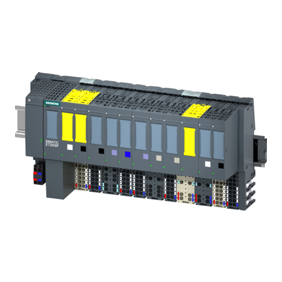
Product overview Properties Article number 6ES7136-6CB00-0CA0 Firmware version This manual describes the properties of the module with firmware version 1.00 or later. View of the module ① Module type and name ⑦ Function class ② LED for diagnostics ⑧ Electronic coding element connector (not shown) ③... - Page 15 The F-TM Count module reports events and statuses based on configured parameters and external movement operations in the SIMATIC ET 200SP distributed I/O system. It provides a SIN/COS encoder interface that can safely count up to a maximum speed of 200 kHz.
-
Page 16: Functions
• Cable (article number 6FX8008-1BD31-XXXX) sold by the meter or equivalent Article numbers are provided for those items unique to the F-TM Count module. Additional information about accessories can be found in the ET 200SP Distributed I/O System system manual (http://support.automation.siemens.com/WW/view/en/58649293). Functions 2.2.1... -
Page 17: Detection Of Counting Signals
Product overview 2.2 Functions Supported safety monitoring functions The F-TM Count module provides safety monitoring functions that may be used to monitor speed, position, and/or direction. These safety monitoring functions can be optionally enabled to report safety events if configured safety limits are exceeded. The safety monitoring functions include the following: •... -
Page 18: Measured Value Determination
Product overview 2.2 Functions 2.2.3 Measured value determination You can select one at a time from the following measured values reported: • Frequency measurement with the unit of millihertz (-800000000 to +800000000 meaning -800000.000 to +800000.000 Hz) • Period measurement with the unit of microseconds (-25000000 to +25000000 meaning -25.000000 to +25.000000 seconds) •... - Page 19 Product overview 2.2 Functions For example: the figure shows that at a frequency of 100 Hz, the percent error in the measured value is about 10 times greater at a 1 second update time as compared to a 5 second update time. Note The safety reaction time is influenced by the chosen update time when using measured values as part of your safety program (for example, at about 100 Hz, the relative error with a...
- Page 20 Product overview 2.2 Functions Examples of determining measured values Use STEP 7 device configuration to set the values for the module in the following examples. For your velocity in meters per second, you set the "Time Base for Velocity Measurement" field to the value "1 second"...
-
Page 21: Counter Control And Feedback
Product overview 2.2 Functions 2.2.4 Counter control and feedback The safety-related counter input (feedback) and output (control) data are transferred to and from the F-CPU, via the PROFIsafe protocol to ensure the configured system operates safely. Control The following commands are set by your safety program and sent from the F-CPU to the F-TM Count module: •... -
Page 22: Counter Input Diagnostics
Product overview 2.2 Functions • HSC0 Current Value • HSC0 Measured Value See also Refer to "Explanation of parameters (Page 36)" for additional information on the F-TM Count module control interface commands and feedback status and event data. 2.2.5 Counter input diagnostics Counter discrepancy The module uses multiple internal counters to monitor the single counter-module input. - Page 23 Product overview 2.2 Functions Maximum signal frequency The F-TM Count module evaluates the input frequency. When encoder signal frequency reaches the maximum frequency rating (200 kHz), a reintegratable frequency error is generated. WARNING The count value can potentially be affected when exceeding the maximum supported signal frequency.
- Page 24 Product overview 2.2 Functions A and B signal monitoring Signal monitoring evaluates the quality of the A and B signals. The following A and B signal quality faults can cause a channel diagnostic event to be generated. • Phase angle of A and B signal has shifted from 90° •...
-
Page 25: Connecting
Connecting Wiring and block diagram This section provides the block diagram of the F-TM Count 1x1Vpp sin/cos HF module with the terminal assignment. ET 200SP F-TM Count 1x1Vpp sin/cos HF (6ES7136-6CB00-0CA0) Equipment Manual, V1.0, 01/2021, A5E47073911-AA... - Page 26 The BaseUnit is not included with the delivery of the module. You can find information on wiring the BaseUnit, connecting cable shields, etc. in the Connecting section of the ET 200SP Distributed I/O System, system manual (https://support.industry.siemens.com/cs/pl/en/view/58649293). ET 200SP F-TM Count 1x1Vpp sin/cos HF (6ES7136-6CB00-0CA0) Equipment Manual, V1.0, 01/2021, A5E47073911-AA...
- Page 27 Connecting 3.1 Wiring and block diagram Pin assignment of the BaseUnit Table 3- 1 Pin assignment of BaseUnit BU15-P16+A10+2B, BU type A0 Designation Signal name View Signal Designation name SIN/COS differential encoder with or without signal N Encoder signal A Encoder signal A/ Encoder signal B Encoder signal B/...
- Page 28 Connecting 3.1 Wiring and block diagram Encoder signals/count signals The encoder must be a 1Vpp sin/cos encoder. Encoder signal names are defined by the encoder manufacturer and can differ from the signal names used in this manual. Signals herein are designated with the letters A, A/, B, B/, N and N/. A, B and N inputs are differential pairs driven by the encoder.
- Page 29 Connecting 3.1 Wiring and block diagram Wiring using the cable is shown in the following figure: NOTICE The right side of the F-TM Count module may exhibit some sensitivity to electrostatic discharge (ESD). Care should be taken to avoid exposure to ESD. If possible, it is recommended the F-TM Count module is not the last module on the right of the mounted configuration.
-
Page 30: Parameters/Address Space
You have the responsibility to ensure that no unconfigured modules are connected in a fail- safe automation system. Refer to the Configuring chapter of the SIMATIC Safety - Configuring and Programming manual (https://support.industry.siemens.com/cs/ww/en/view/54110126) for step-by-step instructions. Fail-Safe CPUs You can use any of the following F-CPUs with the F-TM Count module: •... -
Page 31: Using Step 7 (Tia Portal V17 Or Greater)
– If successful, the module is now operational. Note Refer to the SIMATIC Safety - Configuring and Programming manual (https://support.industry.siemens.com/cs/ww/en/view/54110126) for further information about PROFIsafe address identification and assignment. ET 200SP F-TM Count 1x1Vpp sin/cos HF (6ES7136-6CB00-0CA0) Equipment Manual, V1.0, 01/2021, A5E47073911-AA... -
Page 32: Using Step 7 (Tia Portal) With Gsdml (Versions Of Tia Portal Prior To V17)
If you need to configure F-modules with a GSDML file, you need the S7-FCT in order to calculate the F_iPar_CRC and assign the PROFIsafe addresses. Operating instructions and additional information for the S7-FCT V2.0 - Fail-safe Configuration Tool can be found on the Internet (https://support.industry.siemens.com/cs/ww/en/view/109763833). You can find S7-FCT on the Internet (https://support.industry.siemens.com/cs/ww/en/view/109762827). - Page 33 3. Use "Assigning the F-source address and F-destination addresses to the F-I/Os" section in the instructions for the S7-FCT V2.0 - Fail-safe Configuration Tool on the Internet (https://support.industry.siemens.com/cs/ww/en/view/109763833) to assign the PROFIsafe address (F-destination address together with F-source address) to the F-module before you put it into operation.
-
Page 34: Reinitialize On Parameterization Download
Parameters/address space 4.2 Reinitialize on parameterization download Reinitialize on parameterization download Each time parameterization of the F-module occurs, reinitialization of internal module states is required. This means that internal module states are equivalent to power-up states. Reinitializing results in the following changes in the module: •... -
Page 35: Reaction To Cpu Stop
Parameters/address space 4.3 Reaction to CPU STOP Reaction to CPU STOP You set the response of the F-TM Count module to CPU STOP for the module in the device configuration. Table 4- 1 Response of technology module to CPU STOP Option Meaning Continue count-... -
Page 36: Parameters Of The F-Tm Count
Parameters/address space 4.5 Parameters of the F-TM Count Parameters of the F-TM Count The following parameter settings are possible: Table 4- 3 Settable parameters and their default setting Parameter Value range Default setting Parameter Scope reassign- STEP 7 (TIA Portal); ment in STEP 7;... - Page 37 Parameters/address space 4.5 Parameters of the F-TM Count Parameter Value range Default setting Parameter Scope reassign- STEP 7 (TIA Portal); ment in STEP 7; GSD file Safety monitoring Measured value Frequency Channel • Frequency • Velocity • Period duration Update time 0 ms to 25000 ms 100 ms Channel...
-
Page 38: Explanation Of Parameters
Parameters/address space 4.6 Explanation of parameters Explanation of parameters 4.6.1 F-parameters Manual assignment of F-monitoring time This is a selection to enable the "Manual assignment of F-monitoring time". F-monitoring time The monitoring time of safety-related PROFIsafe communication occurring between the F- CPU and the F-I/O module. - Page 39 Specifies the symbolic name of the F-I/O DB that is created during compilation. See also S7-FCT V2.0 - Fail-safe Configuration Tool Operating Instructions (https://support.industry.siemens.com/cs/ww/en/view/109763833) SIMATIC Industrial Software SIMATIC Safety - Configuring and Programming (https://support.industry.siemens.com/cs/ww/en/view/54110126) ET 200SP F-TM Count 1x1Vpp sin/cos HF (6ES7136-6CB00-0CA0)
-
Page 40: Tm-C Parameters
Parameters/address space 4.6 Explanation of parameters 4.6.2 TM-C parameters Selection of channel activation Enables channel activation. The counter channel is always activated since there is only a single channel. Selection of operating type: Counting/Position input Enables whether to provide integer counter value. This selection is always enabled for the counter module and a counter value is always returned. - Page 41 Parameters/address space 4.6 Explanation of parameters Pulses per revolution Specifies the total number of Sin/Cos pulses per revolution of the encoder. This is used for N signal plausibility monitoring. This field is only enabled when the "Signal type" selected is sin/cos encoder (A, B, N).
- Page 42 Parameters/address space 4.6 Explanation of parameters Reaction to violation of a counting limit Specifies the reaction when either the high or low counting limit is exceeded. You can choose to either continue counting or to stop counting. If you choose to stop counting, you must close and reopen the software gate to resume counting.
- Page 43 Parameters/address space 4.6 Explanation of parameters Reaction to gate start Specifies whether the count value is set to the start value or continues with the current value when the SW gate is opened. This action occurs each time the SW gate changes from closed to open.
- Page 44 Parameters/address space 4.6 Explanation of parameters Measured value Specifies one of a possible three different engineering unit conversions as follows: • Frequency: The average number of counts per second reported in millihertz (hertz * 1000) • Period duration: The average period between two counts in microseconds (seconds * 1000000) •...
- Page 45 Parameters/address space 4.6 Explanation of parameters Standstill tolerance Specifies the acceptable standstill tolerance allowed for the SOS function measured in counts. Note The standstill tolerance selection is disabled if "Safety Function - Safe Stop" is disabled. Safety Function - Safe Direction Enables safe direction (SDI) monitoring.
- Page 46 Parameters/address space 4.6 Explanation of parameters Safety Function - Limited Speed Enables safety limited speed (SLS) monitoring only when "Velocity" is selected as the measured value. User program set "Enable Safe Speed" high to initiate SLS monitoring Module process the "Enable Safe Speed" value and SLS monitoring is started. Calculated speed exceeds the configured speed limit, "Safe Speed Event"...
- Page 47 Parameters/address space 4.6 Explanation of parameters The calculated speed is updated once per configured update time and represents the average speed over the preceding interval. When determining what update time to use, it is important to consider the update time's effect on filtering of momentary speed limit violations and the overall response time of the SLS monitoring.
- Page 48 Parameters/address space 4.6 Explanation of parameters The actual speed exceeds the configured speed limit during the "n+2" update interval. Due to the averaging of the measured value, the calculated speed never exceeds the speed limit so no safe speed event is issued by the module. Larger update times effectively filter out short speed limit violations.
-
Page 49: Behavior At The Counting Limits
Parameters/address space 4.7 Behavior at the counting limits Behavior at the counting limits "Reaction to violation of a counting limit" selections are defined as follows: • "Continue counting": After a violation of a counting limit, counting surpasses the limit and goes to either the start value or the opposite counting limit (depending upon configuration), and then continues. - Page 50 Parameters/address space 4.7 Behavior at the counting limits Examples The figure below shows an example for terminating the counting process after an overflow and setting the counter to the start value: The figure below shows an example for continuing the counting process after an overflow and setting the counter to the start value: The figure below shows an example for terminating counting after an overflow and setting the counter to the opposite counting limit:...
-
Page 51: Quadrature Evaluation Of Differential Signals
Parameters/address space 4.8 Quadrature evaluation of differential signals The figure below shows an example for continuing the counting process after an overflow and setting the counter to the opposite counting limit: Quadrature evaluation of differential signals With quadrature evaluation, the A and B signals are shifted by 90 degrees in relation to each other. -
Page 52: Safety Functions
Parameters/address space 4.9 Safety functions Safety functions This provides a quick overview of the principle mode of operation of the F-TM Count module safety functions. The description of the safety functions is based on the definition according to standard EN 61800-5-2 and some simple examples for using the function. The description of the functions is simplified, as far as possible, to clearly show essential properties and configuration options. - Page 53 Parameters/address space 4.9 Safety functions Using SOS monitoring The safe stop position is stored when SOS monitoring is initiated by turning on the "Enable Safe Stop" bit and is used for the entire SOS monitoring session. Your safety program examines the "Safe Stop Event" bit in the feedback interface and takes appropriate action during the SOS monitoring session.
-
Page 54: Function Of Sos
Parameters/address space 4.9 Safety functions 4.9.1.1 Function of SOS The SOS function monitors the count value and notifies the user if the encoder/count deviates more than a defined amount from the stopped position. SOS Selection Example of how the function can be used Example Possible solution A protective door can only be opened if a machine... -
Page 55: Example Using Sos Monitoring
Parameters/address space 4.9 Safety functions 4.9.1.2 Example using SOS monitoring The protected machine areas can be entered without having to shut down the machine as long as SOS is active. Machine stopping is monitored using an SOS tolerance window. At the instant this function becomes enabled, the current position is stored as the comparison position until SOS is disabled again. -
Page 56: Safety Limited Speed (Sls)
Parameters/address space 4.9 Safety functions 4.9.2 Safety Limited Speed (SLS) Safe speed monitoring SLS monitoring is initiated whenever the "Enable Safe Speed" bit is set in the control interface and subsequently processed by the F-TM Count module. SLS monitoring terminates whenever the "Enable Safe Speed"... -
Page 57: Function Of Safety Limited Speed (Sls)
Parameters/address space 4.9 Safety functions Using SLS monitoring SLS monitoring is initiated by turning on the "Enable Safe Speed" bit. Your safety program examines the "Safe Speed Event" bit in the feedback interface and takes appropriate action during the SLS monitoring session. Set the "Reset Safe Speed"... -
Page 58: Configuring Sls
Parameters/address space 4.9 Safety functions Examples of how the function can be used Example Possible solution The machine operator must be able to enter the • Enable SLS in the counter via your safety machine after the protective door has been opened program in the F-CPU. -
Page 59: Safe Direction (Sdi)
Parameters/address space 4.9 Safety functions 4.9.3 Safe Direction (SDI) Safe direction (SDI) monitoring SDI monitoring is initiated whenever the "Enable Safe Direction" bit is set in the control interface and subsequently processed by the F-TM Count module. SDI monitoring terminates whenever the "Enable Safe Direction"... - Page 60 Parameters/address space 4.9 Safety functions Using SDI monitoring The safe direction is stored when SDI monitoring is initiated by enabling the "Enable Safe Direction" bit and is used for the entire SDI monitoring session. While the SDI monitoring session is in progress, subsequent changes to the "Safe Direction" bit are ignored. Your safety program examines the "Safe Direction Event"...
-
Page 61: Function Of Safe Direction (Sdi)
Parameters/address space 4.9 Safety functions 4.9.3.1 Function of Safe Direction (SDI) The SDI function monitors the encoder and notifies the user if the encoder/count moves more than a defined amount in the unin- tended direction. Examples of how the function can be used Example Possible solution A protective door can only be opened if a conveyor... -
Page 62: Responding To Sdi
Parameters/address space 4.10 Address space 4.9.3.3 Responding to SDI Your safety program examines the "Safe Direction Event" bit and takes appropriate action when the bit is seen as 1. Once set, the "Safe Direction Event" bit remains set until either of the following actions occur: •... -
Page 63: Control And Feedback Interface
Parameters/address space 4.11 Control and feedback interface 4.11 Control and feedback interface 4.11.1 Assignment of the control interface Your safety program uses the control interface to influence the behavior of the F-TM Count module. Control interface The following table shows the assignment of the control interface: Byte Bit 7 Bit 6... - Page 64 Parameters/address space 4.11 Control and feedback interface Byte Control bit/value Explanations Reset Safe Direction The "Reset Safe Direction" bit is used to reset the "Safe Direction Event" bit in the feedback interface. • 0: No action • 1: Clear the "Safe Direction Event" bit As long as the "Reset Safe Direction"...
-
Page 65: Assignment Of The Feedback Interface
Parameters/address space 4.11 Control and feedback interface 4.11.2 Assignment of the feedback interface Your safety program receives current values and status information from the F-TM Count module by means of the feedback interface. Feedback interface The following table shows the assignment of the feedback interface: Byte Bit 7 Bit 6... - Page 66 Parameters/address space 4.11 Control and feedback interface Byte Feedback bit/value Explanations Reset Safe Speed Status The "Reset Safe Speed Status" bit is used to acknowledge that the mod- ule has received and reacted to the "Reset Safe Speed" bit in the control interface as follows: •...
- Page 67 Parameters/address space 4.11 Control and feedback interface Byte Feedback bit/value Explanations Underflow Event The "Underflow Event" bit is set whenever the current count value ex- ceeds the configured "Low Counting Limit". • 0: No violation of limit • 1: Low counting limit was exceeded The "Underflow Event"...
-
Page 68: Applications Of The F-I/O Module
Applications of the F-I/O module Application mode 1: A/B with N Application mode 1: A/B with N The F-TM Count module supports the following application mode: • A, B differential encoder signals • N pulse per revolution differential encoder signal The figure below is an example of the A/B with N application mode: Note The encoder may also be powered from an external source. -
Page 69: Application Mode 2: A/B Without N
Applications of the F-I/O module 5.2 Application mode 2: A/B without N Application mode 2: A/B without N Application mode 2: A/B without N The F-TM Count module supports the following application mode: • A, B differential encoder signals The figure below is an example of the A/B without N application mode: Note The encoder may also be powered from an external source. -
Page 70: Interrupts/Diagnostic Messages
Interrupts/diagnostic messages Reactions to faults Reactions to startup of the fail-safe system and to faults The fail-safe concept depends on the identification of a safe state for all process variables. The safety function requires that safe state values be applied to the fail-safe channel instead of process values (passivation of the fail-safe module or channel) in the following situations: •... - Page 71 Interrupts/diagnostic messages 6.1 Reactions to faults Reintegration of a fail-safe module A channel or module can be reintegrated after successful diagnostics determine that a fault has cleared. The F-TM Count module requires that counting faults such as N-signal, discrepancy, frequency, and A and B signal monitoring must be cleared for at least 10 seconds before allowing reintegration.
- Page 72 Do not depend on channel or module passivation to maintain safe state for more than 100 hours. Additional information on passivation and reintegration For further information about fail-safe module access, refer to the SIMATIC Safety - Configuring and Programming manual (https://support.industry.siemens.com/cs/ww/en/view/54110126). ET 200SP F-TM Count 1x1Vpp sin/cos HF (6ES7136-6CB00-0CA0) Equipment Manual, V1.0, 01/2021, A5E47073911-AA...
-
Page 73: Status And Error Display
Interrupts/diagnostic messages 6.2 Status and error display Status and error display LEDs The following figure shows you the LED displays (status and error displays) of F-TM Count module: ① DIAG (green/red) ⑤ N (green) ② A (green) ⑥ UP (green) ③... - Page 74 Interrupts/diagnostic messages 6.2 Status and error display DIAG LED The DIAG LED indicates system and module faults. Table 6- 1 Meaning of the DIAG LED DIAG Meaning Backplane bus supply of the ET 200SP is not OK Module reintegratable diagnostic event has been resolved and the module or channel is awaiting reinte- gration.
- Page 75 Interrupts/diagnostic messages 6.2 Status and error display N LED The N LED indicates the current level of the counter N pulse signal from the encoder. The N LED will show the state of the N signal only when the encoder is configured as A/B with N. The N LED will be in the ON state if the N signal is disconnected (but configured).
-
Page 76: Interrupts
Interrupts/diagnostic messages 6.3 Interrupts Interrupts Diagnostic interrupts The F-module generates a diagnostic interrupt for each diagnostics alarm described in Diagnostic messages (Page 75). The table below provides an overview of the diagnostic interrupts of the F-module. The diagnostic interrupts are assigned either to one channel or the entire F-module: Table 6- 6 Diagnostic interrupts of the F-TM Count module Diagnostic interrupt... -
Page 77: Diagnostic Messages
Interrupts/diagnostic messages 6.4 Diagnostic messages Diagnostic messages Diagnostic alarms The display of diagnostics is in plain text in STEP 7 in the online and diagnostics view. You can evaluate the error codes with your safety program. Note If you use a GSDML file for configuration, the diagnostic alarm text is only available in the project that installed the GSDML. - Page 78 Interrupts/diagnostic messages 6.4 Diagnostic messages The following diagnostics can be signaled: Table 6- 7 Diagnostics alarms, their meaning and possible remedies Diagnostics alarm Fault Meaning Solution code Overtemperature 16#0005 An excessively high temperature was • Operate the F-module within the measured in the F-module.
- Page 79 Interrupts/diagnostic messages 6.4 Diagnostic messages Diagnostics alarm Fault Meaning Solution code Mismatch of safety desti- 16#0040 The PROFIsafe driver has detected a dif- • Check the parameter assignment of nation address ferent F-destination address. the PROFIsafe address assigned to (F_Dest_Add) Checked after new parameters received.
- Page 80 Interrupts/diagnostic messages 6.4 Diagnostic messages Diagnostics alarm Fault Meaning Solution code No pulses detected 16#030A The expected number of pulses was not • Check the N signal process wiring. received within a given revolution, where • Check the parameter is set to the revolution is determined by the mod- ule receiving an active N signal event.
- Page 81 Interrupts/diagnostic messages 6.4 Diagnostic messages Diagnostics alarm Fault Meaning Solution code Failure in the input circuit 16#0313 The F-module has detected an internal • Replace defective F-module. error in the input circuits. Possible cause: • F-module is defective Internal discrepancy 16#0315 The internal counters of the F-module •...
-
Page 82: Value Status (Cq Hsc0)
You can find the assignment in section Address space (Page 60). Reference A detailed description of the evaluation and processing of the value status can be found in the SIMATIC Safety – Configuring and Programming manual (https://support.industry.siemens.com/cs/ww/en/view/54110126). ET 200SP F-TM Count 1x1Vpp sin/cos HF (6ES7136-6CB00-0CA0) Equipment Manual, V1.0, 01/2021, A5E47073911-AA... -
Page 83: Technical Specifications
Technical specifications Specifications 6ES7136-6CB00-0CA0 General information Product type designation F-TM Count, 1x1Vpp sin/cos HF Firmware version V1.0 FW update possible Product version V1.0 usable BaseUnits BU type A0 Color code for module-specific color identification CC01 plate Product function I&M data Yes;... - Page 84 Technical specifications 7.1 Specifications 6ES7136-6CB00-0CA0 Digital input functions, parameterizable Gate start/stop Counter for incremental encoder Number, max. Input voltage Type of input voltage sin/cos 1 Vpp Input delay (for rated value of input voltage) Minimum pulse width for program reactions 2.5 µs for parameterization "none"...
- Page 85 Technical specifications 7.1 Specifications 6ES7136-6CB00-0CA0 Integrated Functions Number of counters Counting frequency (counter) max. 800 kHz; with quadruple evaluation Safety monitoring functions Safe Operating Stop (SOS) Safely-Limited Speed (SLS) Safe Direction (SDI) Safe Speed Monitor (SSM) Counting functions Continuous counting Counter response parameterizable Software gate Counting range, parameterizable...
- Page 86 Technical specifications 7.1 Specifications 6ES7136-6CB00-0CA0 Highest safety class achievable in safety mode Performance level according to ISO 13849-1 Cat. 4, PL e SIL acc. to IEC 61508 SIL 3 Probability of failure (for service life of 20 years and repair time of 100 hours) Low demand mode: PFDavg in accordance with 2.00E-03 signal monitoring disabled SIL 1...
-
Page 87: Response Times
You can calculate your maximum system response time using the "SIMATIC STEP 7 Safety Advanced: F-Execution Times, F-Runtimes, F-Monitoring and Reaction Times (https://support.industry.siemens.com/cs/ww/en/view/58856512)" Excel file (RT_calculator). Use your configured individual fail-safe module timing parameters and the module characteristic parameters found in this appendix to determine the maximum response time of your system. - Page 88 Response times A.2 Response times of the F-TM Count module Maximum fault response time of the F-module input = (T * 2) + T (when moving) WCDT_i cycle signal = (T * 2) + T (when not moving or moving slower than a single count per OFDT_i cycle diagrep...
-
Page 89: Parameter Data Record
Parameter data record Parameter defaults and dependencies when configuring with GSD file When configuring the module with a GSD file, remember that the setting of some parameters are dependent on each other. F-TM Count module and encoder The following are F-TM Count module default parameters: Channel activation Count/Pos input Measuring... - Page 90 Parameter data record B.1 Parameter defaults and dependencies when configuring with GSD file Safety monitoring The following are safety monitoring default parameters: SOS enable SDI enable SLS enable Disabled Disabled Disabled SOS tolerance SDI tolerance SLS speed When SLS is enabled, a measured value other than velocity will result in a parameter error. ET 200SP F-TM Count 1x1Vpp sin/cos HF (6ES7136-6CB00-0CA0) Equipment Manual, V1.0, 01/2021, A5E47073911-AA...