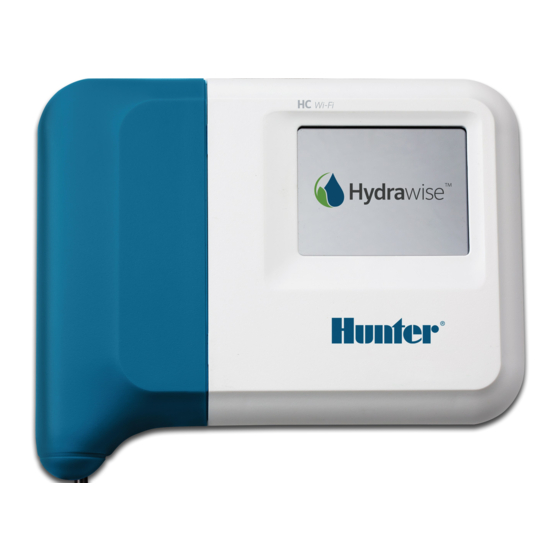
Hunter Hydrawise HC Owner's Manual
Irrigation controllers
Hide thumbs
Also See for Hydrawise HC:
- Installation manual (36 pages) ,
- Owner's manual (16 pages) ,
- Quick start manual (13 pages)
Table of Contents
Advertisement
Advertisement
Table of Contents

Summary of Contents for Hunter Hydrawise HC
-
Page 2: Table Of Contents
HC - Wire Distance (Controller to Valve) HC - Valve Wiring Solenoid Valve Wiring Connecting the Transformer HC - Controller Mounting CABLE ENTRY ENTRY FROM THE REAR OF THE CONTROLLER ENTRY VIA ¾ INCH CONDUIT MOUNTING THE CONTROLLER Copyright 2020 Hunter Industries. All Rights Reserved. -
Page 3: Hc Hydrawise - Quick Start Guide
So the master valve is a little like a backup valve or a fail-safe valve. The purpose of the master valve is to shut off the water to the Copyright 2020 Hunter Industries. All Rights Reserved. -
Page 4: How Is It Configured
With a Hydrawise controller, any one of your 6 / 12 zones can be configured to act as a master valve. The master zone is configured on the Zones & Schedules page above your Copyright 2020 Hunter Industries. All Rights Reserved. -
Page 5: Hc - Wire Distance (Controller To Valve)
Master valve. HC - Wire Distance (Controller to Valve) Below is a chart indicating the maximum wire runs that can be used when installing Hunter AC solenoids and valves. Copyright 2020 Hunter Industries. All Rights Reserved. -
Page 6: Hc - Valve Wiring
Refer to the diagram below when connecting your solenoid valves to the controller. Please click on the link below for the downloadable version of the controller to valve wiring diagram. Hydrawise Controller Connection Diagram Copyright 2020 Hunter Industries. All Rights Reserved. -
Page 7: Solenoid Valve Wiring
1. Use the plug pack supplied and connect the wires to the red AC terminal blocks on the unit marked as 24V. Polarity of the wiring is not important. 2. Turn the power on. The power indicator will light up. Copyright 2020 Hunter Industries. All Rights Reserved. -
Page 8: Hc - Controller Mounting
2. Insert plastic anchor so it is flush with the surface of the wall. 3. Screw 1 inch screw into plastic anchor leaving the head protruding about 1/8 inch (4 mm). 4. Slide the controller case over the screw head. Copyright 2020 Hunter Industries. All Rights Reserved. - Page 9 Rear cable entry point (remove with knife) Conduit cable entry point (remove with knife) Wall mounting screw hole Power indicator Expansion module cable entry Go to previous screen Go to home screen STEPS 1-5 Copyright 2020 Hunter Industries. All Rights Reserved.


