Sony LIB-D81 Product Description Manual
Ait autoloader
Hide thumbs
Also See for LIB-D81:
- Operating instructions manual (56 pages) ,
- Quick start quide (24 pages)

Related Manuals for Sony LIB-D81


Summary of Contents for Sony LIB-D81
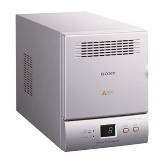
- Page 1 AIT Autoloader Product Description Manual Version 2.0 - March 2003 LIB-D81 Sony Corporation 200305001...
- Page 2 This document contains proprietary information which is protected by copyright. All rights reserved. No part of this document may be photocopied, reproduced or translated to another language without prior written consent of Sony. The information contained in this document is subject to change without notice.
-
Page 3: Table Of Contents
Table of Contents Chapter 1 Introduction 1.1. Overview..............8 1.2. References ............9 Chapter 2 Specifications 2.1. Physical Specifications........10 2.1.1. Dimensions............10 2.1.2. Weight..............11 2.2. Product Features and Functions ......12 2.2.1. Front ..............12 2.2.2. Rear ..............13 2.2.3. Interior (Front) ............ 14 2.2.4. - Page 4 Chapter 3 Installation 3.1. Overview..............22 3.2. Unpacking ............22 3.3. Package Contents ..........23 3.4. Preparing the Host Computer ......23 3.5. Installing the AIT Autoloader......24 3.6. Connecting the Power Cable......25 3.7. Connecting to the Host Computer ....25 3.8. Setting the DIP Switches ........27 3.9.
- Page 5 Chapter 7 SCSI Interface 7.1. Logical Characteristics ........50 7.1.1. Arbitration............50 7.1.2. Selection Response Time ........50 7.1.3. RESELECTION Time-out Procedure (Non-Queued) ............50 7.1.4. ATTENTION Condition ........50 7.1.5. RESET Condition ..........51 7.2. Message ..............52 7.2.1. Supported Messages..........52 7.3.
- Page 6 8.10.4. VOLUME LIST service action ....... 101 8.10.5. ELEMENT LIST service action ..... 101 8.10.6. Medium Auxiliary Memory Attribute Data ..102 8.10.7. ATTRIBUTE ID values ........103 8.10.8. Device Common Attributes ......104 8.10.9. Medium Common Attributes ......104 8.10.10.
- Page 7 8.22.5. Buffer ID ............135 8.22.6. Buffer Offset ........... 135 8.22.7. Parameter List Length........135 Appendix A.1. ASC & ASCQ in Alphabetical Order ....136 A.2. ASC & ASCQ in Numerical Order ....138 A.3. SCSI Commands (OP CODE Order) ....140 A.4. Cleaning the Air Filter........140 A.5.
-
Page 8: Chapter 1 Introduction
Chapter 1.1. Overview The LIB-D81 is a desktop AIT (Advanced Intelligent Tape) automatic loader (hereafter, “AIT autoloader”) with a built-in AIT drive. Up to 8 cartridges can be inserted in the AIT autoloader. The unit can also be connected to and used with a workstation or server. -
Page 9: References
1.2. References Please refer to the following documents for additional information: • Small Computer System Interface (SCSI-1), ANSI X3.131-1986 The ANSI authorized standard for SCSI implementation, available through ANSI • Enhanced Small Computer Systems Interface (SCSI-2) ANSI S319.2/86-109 (Revision 10H, or above), available through ANSI •... -
Page 10: Chapter 2 Specifications
Specifications Chapter Physical, environmental and performance specifications of the LIB-D81. 2.1. Physical Specifications 2.1.1. Dimensions +1.5 Height 224.0 mm (8.9 in) Width 170.0 ± 1.0 mm (6.7 in) Depth 350.0 ± 1.0 mm (13.8 in) Chapter 2 Specifications... -
Page 11: Weight
Rubber feet Rubber fett 265mm / 10.433 inch 38mm / 1.496 inch 0.039 170± 1mm / 6.7 – inch Rubber feet Rubber feet 0.039 350±1mm / 8.9 – inch 2.1.2. Weight • LIB-D81: 7.0 kg (15.4 lb.) Chapter 2 Specifications... -
Page 12: Product Features And Functions
2.2. Product Features and Functions 2.2.1. Front AIT LIBRARY LIB-D81 CLEAN DOOR ERROR WARNING CLEANING A Ventilation Holes Be careful not to block the ventilation holes. If the ventilation holes are blocked, the AIT autoloader may overheat, resulting in damage. -
Page 13: Rear
2.2.2. Rear A Setup DIP Switches and DIP Switch Cover Used to set up the AIT autoloader. Remove the screws and cover to access the DIP switches. For details, see “Setting the DIP Switches” (page 27). B Ventilation Holes Please be careful not to block the ventilation holes. If the ventilation holes are blocked, the AIT autoloader may overheat, resulting in damage. -
Page 14: Interior (Front)
2.2.3. Interior (Front) AIT LIBRARY LIB-D81 CLEAN DOOR ERROR WARNING CLEANING A Front Door B Air Filter Periodically clean the air filter with a vacuum cleaner (we recommend monthly cleaning). For details about how to replace the air filter, see “Cleaning the Air Filter”... -
Page 15: Ait Drive (Front)
2.2.4. AIT Drive (Front) BUSY TAPE STATUS A Cartridge Slot Used to insert and eject AIT cartridges from the AIT drive. B STATUS LED Lights when the cartridge in the drive is write-protected. It flashes in the following situations. Drive needs cleaning Repetitive long on, short off. -
Page 16: Environmental Specifications
2.3. Environmental Specifications Note The specifications which apply when media is present may be different than these. 2.3.1. Temperature and Humidity Range Temperature Operating 5°C to 40°C (T < 10°C/h) Non-Operating (mech.) -40°C to 60°C (T < 20°C/h) Non-Operating (tape) -40°C to 45°C (T <... -
Page 17: Acoustic Noise
: No operation failure : No damage 2.3.7. Orientation The LIB-D81 can be installed in three different mounting positions as shown in the figure below. Each position has a maximum tolerance of ±3 degrees. Also, set the autoloader horizontally so that its front and sides are inclined by no more ±3 degrees in any... -
Page 18: Performance Specifications
For this time, use the catalog value. (30 sec (typical)) 2.4.5. Mean Time To Repair The Mean Time To Repair (MTTR) of the LIB-D81 is 30 minutes. Since at the field level the entire drive is considered a Field Replaceable Unit (FRU) the time to replace the drive with a new one is less that 30 minutes. -
Page 19: Mean Swaps Between Failures
• TÜV EN 60950 • IEC 60950 2.6. Installation Requirements Note Do not move the LIB-D81 while it is operating. It may cause malfunctions. 2.6.1. Power Requirements 100 to 120 V ± 10% 0.7 A (50/60 Hz) 200 to 240 V 0.35 A (50/60 Hz) -
Page 20: System Structure
AIT autoloader to a host computer equipped with an Ultra 160 SCSI LVD/SE interface. The autoloader is controlled through the host computer. Computer Ethernet (example) LIB-D81 68-pin cable SCSI AIT LIBRARY LIB-D81 Host computer CLEAN DOOR ERROR SCSI peripheral devices WARNING... -
Page 21: Cleaning Cartridge
AIT-3 Drive AIT-3 mark AIT-1 mark AIT-2 mark Caution Do not use 8 mm video tapes sold at stores. An 8 mm video tape looks a lot like an AIT cartridge, but has different specifications. Do not use any other cartridges other than AIT cartridges. -
Page 22: Overview
Installation Chapter 3.1. Overview This chapter explains general procedures for positioning the AIT autoloader, connecting it to the host computer and turning on the AIT autoloader. This chapter also explains initial setup. Installation and setup procedures may vary depending on your system. 3.2. -
Page 23: Package Contents
3.3. Package Contents After opening the box, make sure that all the following items are present. Contact your dealer if anything is missing. • LIB-D81 (1) • Power cable (1) • SCSI terminator (1) • Cleaning cartridge (1) • Quick Start Guide (1) •... -
Page 24: Installing The Ait Autoloader
3.5. Installing the AIT Autoloader The autoloader weighs about 7 kg (15.4 lb.) and has the following dimensions. Before installing the autoloader, make sure that the surface is appropriate. Note Install the AIT autoloader on a horizontal surface near an AC power outlet. Also leave a gap of about 150 mm (5.9 in.) behind the rear of the unit to allow air to circulate. -
Page 25: Connecting The Power Cable
3.6. Connecting the Power Cable Make sure that the power switch on the rear of the AIT autoloader is in the off position (a is depressed). Connect one end of the power cable to the power supply connector and the other end to the power outlet. - Page 26 • When connecting the Wide SCSI cable, turn off all of the connecting devices, including the AIT autoloader and the host computer. • When connecting the AIT autoloader as the last device on the SCSI bus, be sure to attach the provided terminator. •...
-
Page 27: Setting The Dip Switches
3.8. Setting the DIP Switches By setting the DIP switches at the back of the AIT autoloader, you can: • Supply power to the SCSI terminator (on by default) When you are using several SCSI devices, you can set the AIT autoloader to supply power to the SCSI terminator. - Page 28 2 MAINTENANCE (on) 0: Warning messages are not displayed when specific parts reach the end of their service life or when in need of cleaning (weekly). 1: Warning messages are displayed when specific parts reach the end of their service life or when in need of cleaning (weekly). 3 LOADER SEL (off) 0: The autoloader option function is not active.
-
Page 29: Setting The Scsi Id
3.9. Setting the SCSI ID Use the SCSI ID switches at the back of the AIT autoloader to set the AIT drive and/or AIT autoloader SCSI ID. The default settings of the switches are as follows. Use the upper switch to set the AIT drive SCSI ID and the lower switch to set the AIT autoloader SCSI ID. -
Page 30: Connecting Scsi Peripheral Devices
3.10. Connecting SCSI Peripheral Devices SCSI peripheral devices can be connected to the SCSI connectors of the AIT autoloader. The SCSI configuration of the autoloader is as shown below. Connect the devices according to the system environment. AIT drive SCSI ID : 0 SCSI connectors Loader controller SCSI ID : 1... - Page 31 The message display changes as follows and the startup process begins. (Startup takes several minutes.) During startup, the following appears on the message display. Moves gradually up and down during the elevator check. Indicates the startup phase, from 0 to 3. When startup is complete, the message display indicates the number of cartridges in the AIT autoloader.
-
Page 32: Turn Off The Power
3.11.2. Turn Off the Power Press the power switch on the rear of the AIT autoloader to turn it off. Caution Do not turn off the AIT autoloader when it is in use or there is a cartridge in the AIT drive, as this could damage data. -
Page 33: Inserting Cartridges
3.12.2. Inserting Cartridges Insert cartridges into the AIT autoloader as outlined below. On the front of the AIT autoloader, press the DOOR button. [o P] flashes on the message display. The AIT autoloader is preparing to open the front door. Wait until the display stops flashing, which may take up to a minute. - Page 34 Make sure that you insert cartridges in the right direction, and push them in the AIT autoloader until you hear a click. Slot in the AIT autoloader are numbered 1 to 8, from the highest slot down. (Slot numbers match SCSI element numbers.) AIT LIBRARY LIB-D81 CLEAN DOOR ERROR...
-
Page 35: Setting Application Software
3.14. SCSI 68-pin Connector Figure 3-6 illustrates SCSI 68-pin connector, and Table 3.14.1 shows the assignments for the pins of the connector. Figure 3-6: Non-Shielded SCSI Device Connector LIB-D81 supports only Low-Voltage-Differential SCSI Configuration as shown Table 3.14.1. Chapter 3 Installation... - Page 36 -BSY +BSY -ACK +ACK -RST +RST -MSG +MSG -SEL +SEL -C/D +C/D -REQ +REQ -I/O +I/O -DB(8) +DB(8) -DB(9) +DB(9) -DB(10) +DB(10) -DB(11) +DB(11) Table 3.14.1 : LIB-D81 SCSI Signals (Low-Voltage-Differential Type BUS P Cable ignal Assignment) Chapter 3 Installation...
-
Page 37: Overview
Basic Usage Chapter 4.1. Overview This chapter explains the control panel, basic settings, handling cartridges, element address assignments, and Maintenance. 4.2. Control Panel You can use the control panel to display information about the AIT autoloader and clean the AIT drive. This section explains the operation of the control panel and the information displayed by the message display. -
Page 38: Message Display
4.2.2. Message Display The message display displays the current number of cartridges in the AIT autoloader, the AIT autoloader’s operational status, as well as warning and error messages. Left of the display ERROR WARNING CLEANING Right of the display Normal display •... -
Page 39: Errors
High internal temperature The ERROR/WARNING LED lights orange and the [0 6] code appears on the message display. Suspend operation or lower ambient temperature. When the AIT autoloader internal temperature returns to normal levels, the ERROR/ WARNING LED goes out. It is possible for the air filter to become clogged with dust or other particles. -
Page 40: Disaster Recovery Function
Example: Problem with the autoloader [L ] and [XX], where “XX” is the error code, appear alternately on the message display. Example: Problem with the drive [d ] and [XX], where “XX” is the error code, appear alternately on the message display. -
Page 41: Assigned Element Addresses
4.6. Assigned Element Addresses An element is a physical location where a cartridge is kept. Applications use element addresses to differentiate between the elements of the AIT autoloader. In AIT autoloader, the element addresses are assigned to the cartridge slots and the AIT drive as illustrated below. -
Page 42: Storing
• If the AIT autoloader is used in a high-humidity environment or a location that is subject to wide variations in temperature, condensation may prevent the cartridge read/write operation. • If the cartridge does not need to be written to or read from, do not insert or eject it too often. -
Page 43: Overview
Operating the AIT Autoloader Chapter 5.1. Overview This chapter explains how to eject and change cartridges. 5.2. Using Cartridges This section explains how to eject and change cartridges. For information about how to prepare and insert cartridges, see “Inserting Cartridges” (page 33) in Chapter 3, “Installation”. 5.2.1. - Page 44 The AIT autoloader is preparing to open the front door. Wait until the display stops flashing, which may take up to a minute. Flashing display Steady display When the display stops flashing, the front door unlocks. Note To prevent the front door from opening during operation, it automatically locks when it is closed.
- Page 45 Eject the cartridge from the slot as illustrated below. AIT LIBRARY LIB-D81 DOOR CLEAN ERROR WARNING CLEANING Caution The AIT autoloader contains a large number of wires and parts. Do not touch any part other than the slots inside the AIT autoloader as this may lead to damage and/or injury.
-
Page 46: Overview
Cleaning the AIT Drive Chapter 6.1. Overview To guarantee the best performance of your AIT autoloader at all times, we recommend that you clean the AIT drive weekly with a cleaning cartridge. By default, the "2 Maintenance" DIP switch on the back of the AIT autoloader is set to ON. - Page 47 CL/8 (the lowest slot). For details about how to insert a cartridge into a slot, see “Setting Cartridges” (page 32) in Chapter 3, “Installation”. Cleaning cartridge AIT LIBRARY LIB-D81 DOOR CLEAN ERROR WARNING...
- Page 48 On the front of the AIT autoloader, press the CLEAN button for at least three seconds. [C L] flashes on the message display and cleaning starts. Flashing display When cleaning ends, the cleaning cartridge is returned to slot CL/8 and the CLEANING LED goes out.
- Page 49 If there is no cartridge in slot CL/8 The ERROR/WARNING LED lights and [0 3] appears on the message display. ERROR WARNING CLEANING If there is an AIT cartridge in slot CL/8 The ERROR/WARNING LED lights and [0 4] appears on the message display.
-
Page 50: Chapter 7 Scsi Interface
SCSI Interface Chapter 7.1. Logical Characteristics 7.1.1. Arbitration The autoloader does not support Disconnect-Reconnect mode page 02h. 7.1.2. Selection Response Time The autoloader responds to a selection within 200 µs. Note This specification does not apply after reset or after turning on the autoloader. 7.1.3. -
Page 51: Reset Condition
7.1.5. RESET Condition The autoloader never applies a bus reset. RESET Handling When a reset condition occurs, the autoloader carries out the following processes: a) Hardware initialization b) Internal parameter initialization c) Position measurement d) Building cassette data UNIT ATTENTION Condition When a BUS DEVICE RESET message, hard reset, or power-on reset occurs, the autoloader issues a UNIT ATTENTION condition to each LUN and initiator. -
Page 52: Message
7.2. Message 7.2.1. Supported Messages The autoloader supports the following messages. Code Description Direction TASK COMPLETE EXTENDED MESSAGE SAVE DATA POINTER RESETORE POINTERS DISCONNECT INITIATOR DETECTED ERROR ABORT MESSAGE REJECT NO OPERATION MESSAGE PARITY ERROR BUS DEVICE RESET IGNORE WIDE RESIDUE 80-C0h IDENTIFY Table 7.2.1.1 : Message Description... - Page 53 Code Extended Message MODIFY DATA POINTER SYNCHRONUS DATA TRANSFER REQUEST Reserved WIDE DATA TRANSFER REQUEST PARALLEL PROTOCOL REQUEST 05-ffh Reserved Table 7.2.1.3 : Extended Message Code MODIFY DATA POINTER: Not supported. SYNCHRONOUS DATA TRANSFER REQUEST determines the format of the parameter for synchronous data transfers. The values are shown in the following table.
- Page 54 WIDE DATA TRANSFER REQUEST Perform negotiation of data width in data transfers. Byte Extended Message(01h) Extended Message Length(02h) WIDE DATA TRANSFER REQUEST(03h) TRANSFER WIDTH EXPONENT(m) Table 7.2.1.6 : WIDE DATA TRANSFER Message Format Responding SCSI device WDTR response Implied agreement TRANSFER WIDTH EXPONENT = 1 16-bit data transfer TRANSFER WIDTH EXPONENT = 0...
- Page 55 The autoloader performs the following processing depending on the setting of protocol option bits QAS_REQ, DT_REQ, and U_REQ. QAS_REQ DT_REQ IU_REQ Description Use ST DATA IN and ST DATA OUT phases to transfer data Use DT DATA IN and DT DATA OUT phases with data group transfers (not supported) Use DT DATA IN and DT DATA OUT phase with information unit transfers (not supported)
- Page 56 05h: INITIATOR DETECTED ERROR The INITIATOR DETECTED ERROR message from the host to the autoloader indicates that an error (such as a parity error) has occurred. Note that the autoloader does not hinder retry processing. After moving to the STATUS phase, a CHECK CONDITION is reported.
-
Page 57: Status
Number of Bytes to Ignore: Indicates the number of invalid bytes in the data transfer. Only 01h (DB15-8) is supported. 80-C0h: IDENTIFY The IDENTIFY message is returned to connect the host and the autoloader logical unit. Byte IDENTIFY DISCPRIV Table 7.2.1.12 : IDENTIFY Message Format When the IDENTIFY bit is 1, this message is an IDENTIFY message. -
Page 58: Multi-Initiator
In addition to the autoloader commands above, the following commands also issue this status. Log Select Mode Select Mode Sense Prevent/Allow (Prevent<>0) Read Attribute Read Buffer Receive Diagnostic Send Diagnostic Test Unit Read Write Buffer 7.4. Multi-Initiator 7.4.1. Reset Handling The autoloader reports valid standard INQUIRY data to an INQUIRY command for all multi-initiators one second after reset. -
Page 59: Chapter 8 Scsi Commands
SCSI Commands Chapter The autoloader supports the following commands. Section Command name Operation code INITIALIZE ELEMENT STATUS INQUIRY LOG SELECT LOG SENSE MODE SELECT (6) MODE SENSE (6) MOVE MEDIUM POSITION TO ELEMENT PREVENT/ALLOW MEDIUM REMOVAL 8.10 READ ATTRIBUTE* 8.11 READ BUFFER 8.12 READ ELEMENT STATUS... -
Page 60: Initialize Element Status Command (07H)
8.1. INITIALIZE ELEMENT STATUS command (07h) The INITIALIZE ELEMENT STATUS command directs the autoloader to initialize all elements and related states. This command is issued, for example, after the status is changed by an operator and is used to initialize the internal state. -
Page 61: Inquiry Command (12H)
Peripheral device type RMB(1) Device-type modifier(00h) ISO version(0) ECMA version(0) ANSI-approved version(2) AENC TrmIOP Reserved(0) Response data format(2) Additional length (1Fh) Reserved(0h) Reserved(0h) RelAdr WBus32 WBus16 Sync Linked Reserved CmdQue SftRe (MSB) Vendor identification "SONY" (LSB) Chapter 8 SCSI Commands... - Page 62 Byte (MSB) Product identification "LIB-D81" (LSB) (MSB) Product revision level (LSB) Table 8.2.1.1 : Standard INQUIRY data format The Peripheral Qualifier and Peripheral device-type fields indicate the connected logical unit devices. The autoloader only supports logical unit 0. Therefore, when LUN is zero, 08h is returned; when LUN is not zero, 7fh is returned.
- Page 63 The ISO and ECMA version values are defined by the International Organization for Standardization and the European Computer Manufacturers Association. The ANSI-approved version field indicates the implementation version defined by the International Standard. This field is set to 02h. Code Description The device might or might not comply to an ANSI-approved standard.
-
Page 64: Vital Product Data
This field contains "SONY". The Product identification field contains an ASCII 16-byte product name as determined by the vendor. This field contains "LIB-D81". The Product revision level field contains an ASCII production revision level as determined by the vendor. - Page 65 The product serial number field contains an ASCII serial number as determined by Sony. If the number of digits is less than a certain value, ASCII "0" (30h) characters are added. If the serial number is invalid, this field is filled with ASCII spaces (20h).
- Page 66 Byte Description 00--15 00 83 00 34 02 01 00 24 53 4f 4e 59 20 20 20 20 ...4..."SONY 16--31 41 75 74 6f 6c 6f 61 64 65 72 20 4c 49 42 2d 44 Autoloader LIB-D 32--47 38 31 20 20 31 32 33 34 35 36 37 38 01 02 00 08 81 12345678..
-
Page 67: Command Support Data
SCSI standard. The data format conforms to the definition in Table 8.2.3.1. 100b Reserved. 101b The autoloader supports the tested SCSI operation code in Sony- specific manner. The data format conforms to the definition in Table 8.2.3.1. 110b Reserved. -
Page 68: Log Select Command (4Ch)
For example, the CDB Usage map of the autoloader INQUIRY command is 12h, 03h, FFh, 00h, FFh, 00h. Note: The first byte is the Operation Code, but the remaining bytes are the Usage map. 8.3. LOG SELECT Command (4Ch) The LOG SELECT command allows access to the autoloader statistics. Parameters in Log Page determine how the LOG DATA is processed. -
Page 69: Log Sense Command (4Dh)
To set the Current threshold value to its default value, set the PC field to 10b, the Parameter List Length to 0, and issue the LOG SELECT command. (Note that the host cannot set the Current threshold value to an arbitrary value using the LOG SELECT command.) To set the Current cumulative values to default values, set the PC field to 11b, the Parameter List Length to 0, and issue the LOG SELECT command. - Page 70 When the SP bit is 0, the autoloader executes the specified LOG SENSE command, but does not save Log Parameters. The Page Control (PC) field specifies the type of parameter values. The values specified in the Page Control field are shown in Table 8.4.2. The parameters returned by the LOG SENSE command are determined as follows.
- Page 71 Each Log Parameter comprises a 4-byte Parameter Header, followed by one or more bytes of Parameter Data. The Parameter Code field indicates the Log Parameter(s) of the Log Page to be transferred. The DU, DS, TSD, ETC, TMC, and LP fields indicate Parameter control references.
-
Page 72: Upported
8.4.1. upported page code The Log Page Codes supported by the autoloader are shown in Table 8.4.1.1. Page code Description Supported log pages Non-medium error page TapeAlert page Autoloader Statistics Log page State Log page History Log page Table 8.4.1.1 : Log page codes 8.4.2. -
Page 73: Tapealert Page
Non-medium error event parameter codes supported by the autoloader are shown in Table 8.4.3.2. Parameter code Description 0000h Non-medium error count 0001h - 7FFFh Reserved 8000h Reserved 8001h Pick & Place Error counts 8002h Elevator Error counts 8003h Fan Error counts 8004h Drive Loading Error counts 8005h... - Page 74 The autoloader returns error details to the host with the following flags. Each flag is cleared to zero by the following events. - Autoloader is restarted - Autoloader is restored by a recovery operation - Host reads an Alert Log Page There are three types of TapeAlert flags.
- Page 75 Flag Type Required Host Message Cause Autoloader General environmental conditions inside the Autoloader temperature limits Temperature Limits autoloader are outside the specified temperature exceeded. range. The autoloader supports this flag. Autoloader Voltage The voltage supply to the autoloader is outside Autoloader voltage limits exceeded.
- Page 76 Flag Type Required Host Message Cause Autoloader Offline The autoloader has been manually turned offline Autoloader manually turned offline and is unavailable for use. Autoloader Drive A drive inside the autoloader has been taken Autoloader turned internal drive Offline offline. offline This is for information purposes only.
-
Page 77: Autoloader Statistics Log Page
8.4.5. Autoloader Statistics Log page This page (page code 30h) returns autoloader robotics operation counts. Byte Reserved(0h) Page code (30h) Reserved(0h) (MSB) Page length (n-3) (LSB) Supported page list Table 8.4.5.1 : Autoloader Log page Mechanical Movement parameter codes supported by the autoloader are shown in Table 8.4.5.2. -
Page 78: History Log Page
The Digital Sensor Parameters supported by the autoloader are shown in Table 8.4.6.2. Parameter code Description 0000h Reserved 0001h Sensor1 (Gap) 0002h Sensor2 (Pass) 0003h Sensor3 (Cartridge) 0004h Sensor4 (Picker Forward) 0005h Sensor5 (Picker Reverse) 0006h Sensor6 (Hand Lower) 0007h Sensor7 (Door Lock) 0008h Sensor8 (Door Close) -
Page 79: Mode Select(6) Command (15H)
Parameter code Description 0000h - 00FFh The history log pointer 0100h - FFFFh Reserved Table 8.4.7.2 : History log parameter codes The History Log Page format is shown in Table 8.4.7.3. Byte (MSB) Parameter Code (LSB) DU(0) DS(1) TSD(0) ETC(0) TMC(0) Reserved LP(1) -
Page 80: Parameter List Header
A Save Pages (SP) bit of 0 directs the autoloader not to save the transferred data to non-volatile memory during the DATA OUT phase. An SP bit of 1 directs the autoloader to save all Mode Pages (including the Mode Pages sent) to non- volatile memory during the DATA OUT phase when performing the specified MODE SELECT processing. - Page 81 The Mode Parameter Block Descriptor to be transferred is as follows. Byte Density code(00h) (MSB) Number of blocks(0000h) (LSB) Reserved(0h) (MSB) Block length(0000h) (LSB) Table 8.5.1.3 : Mode parameter block descriptor The Density Code for the autoloader is 0. The Number of Blocks field for the autoloader is 0. The Block Length for the autoloader is 0.
-
Page 82: Information Exceptions Control Page
8.5.2. Information Exceptions Control Page The Information Exceptions Control Page defines how the autoloader controls particular Informational Exception condition operations and controls how they are returned. Byte PS(0) RSRVD(0) Page Code(1Ch) Page Length(0Ah) Perf(0) Reserved(0) DExcpt Test Reserved LogErro(0) Reserved(0) MRIE (MSB) Interval Timer(00000000h) -
Page 83: Configuration Page
The Return/Count/Test Flag Number field has two different applications. When the TEST bit is 0, the MODE SELECT command indicates the Report Counter in this field. Because the Report Counter field is not supported by the autoloader, the command terminates with a CHECK CONDITION status, and the sense key is ILLEGAL REQUEST when the TEST bit is 0. -
Page 84: Mode Sense(6) Command (1Ah)
8.6. MODE SENSE(6) Command (1Ah) The MODE SENSE(6) command allows the autoloader return held parameters to the host. This command is used in parallel with MODE SELECT(6). Byte Operation code (1Ah) Logical unit number(0h) Reserved Reserved(0h) Page code Reserved(0h) Allocation length Control(0h) Table 8.6.1 : MODE SENSE(6) command When the Disable Block Descriptors (DBD) bit is 0, the MODE SENSE data... -
Page 85: The Mode
8.6.1.2. Changeable values When the PC field is 01b, the autoloader returns a mask indicating changeable Mode Parameters. In this mask, Mode Parameter changeable fields are all 1 and the Mode Parameter unchangeable fields are all 0. Note A request to change an unchangeable Mode Parameter with the MODE SELECT command results in an error. -
Page 86: Mode Parameters
When the Page Code is 3Fh, the autoloader returns all the implemented Mode Pages to the host. Mode Page 00h is returned after all the other Mode Pages. Note Mode Pages are returned in Page Code order except for Mode Page 00h. 8.6.3. - Page 87 8.6.3.1. Device capabilities page The Device Capabilities Page (Table 8.6.3.1.1) defines the characteristics of the Element Types implemented by the autoloader. This information tells the host what functions are allowed to the MOVE MEDIUM command. Byte PS(0) RSRVD(0) Page code (1Fh) Parameter length (12h) Reserved(0h) StorDT...
- Page 88 An XX<>YY bit of 1 indicates that a setting of Element Type XX as Source Element Address and Destination Element Address 2 (when each has the same Address inserted), and settings of Element Type YY as Destination Element Address 1 as a function of the EXCHANGE MEDIUM command is possible. Because the autoloader does not support the EXCHANGE MEDIUM command, the XX<>YY bits are all 0.
- Page 89 8.6.3.2. Element address assignment page The Element Address Assignment Page indicates the assignment of Element Addresses supported by the autoloader. The Element Address Assignment Page also returns the number of each Element Type supported by the autoloader. This page (Element Address Assignment Page) also returns page data in response to a request from the host during Becoming Ready.
- Page 90 Elements indicates the number of internal autoloader Import Export Elements. Because the autoloader is not equipped with Import Export Elements, it is 00h. The First Data Transfer Element Address field indicates the Address of the first internal autoloader Data Transfer Element. In the case of the autoloader, it is 52h.
- Page 91 8.6.3.3. Transport geometry parameters page The Transport Geometry Parameter Page indicates whether there is a Medium Transport Element shared by the autoloader robotics, and whether there is a mechanism to invert a tape cartridge. One Transport Geometry Descriptor contains the information for Medium Transport Elements starting from the First Medium Transport Element.
- Page 92 8.6.3.4. Information Exceptions Control Page The Information Exceptions Control Page allows the autoloader to operate particular Informational Exception conditions and controls their return. Byte PS(1) Reserved Page Code(1Ch) Page Length(0Ah) Perf(0) Reserved(0) DExcpt Test(0) Reserved LogErro(0) Reserved(0) MRIE (MSB) Interval Timer(00000000h) (LSB) (MSB) Report Counter/Test Flag Number...
- Page 93 The Return/Count/Test Flag Number field has two different applications. When the TEST bit is 0, the MODE SELECT command indicates the Report Counter in this field. Because the Report Counter field is not supported by the autoloader, the command terminates with a CHECK CONDITION status, and the sense key is ILLEGAL REQUEST when the TEST bit is 0.
-
Page 94: Move Medium Command (A5H)
The Parity bit specifies whether to check the SCSI bus parity. The specifications are as follows. 0: Do not check the SCSI bus parity. 1: Check the SCSI bus parity (default). Maximum Parity Retries specifies the maximum number of retries after a parity error occurs in the Command Out Phase, Message Out Phase, or Data Out Phase. -
Page 95: Position To Element Command (2Bh)
MEDIUM SOURCE ELEMENT EMPTY in the former case and MEDIUM DESTINATION ELEMENT FULL in the latter case. If the Source Element Address and Destination Element Address are the same, and there is no cartridge in the Element, the command is terminated with a CHECK CONDITION. -
Page 96: Prevent Allow Medium Removal Command (1Eh)
terminated with a CHECK CONDITION. The sense key is ILLEGAL REQUEST and ASC/ASCQ is INVALID ELEMENT ADDRESS. When the Invert bit is 1, the Transport Element is inverted and moved to the specified element. Because the autoloader does not support the inversion function, the Invert bit is always 0. -
Page 97: Read Attribute Command (8Ch)
8.10. READ ATTRIBUTE Command (8Ch) The READ ATTRIBUTE command is used for an application to read the contents of the Medium auxiliary Memory (MAM). Byte Operation code (8Ch) Reserved(0) Service Action MSB) Element address (LSB) Element Type Code Volume Number(0) Reserved(0) Partition Number(0) (MSB) - Page 98 The ELEMENT TYPE CODE indicates the type of the specified Auxiliary Memory address. The Element Type Code values are as follows. 1 Medium Transport Element (autoloader picker, etc.): no hold function 2 Storage Element (autoloader slot, etc.) 3 Import/Export Element (autoloader I/O port, etc.): not supported 4 Data Transfer Element (tape drive, etc.) Note that 4 (Data Transfer Element) returns the value of the slot immediately prior to inserting a cartridge in the drive.
-
Page 99: Attribute Values Service Action
8.10.1. ATTRIBUTE VALUES service action This service action returns the Attribute values for which the PARTITION NUMBER and VOLUME NUMBER can be specified in the READ ATTRIBUTE command, starting with the FIRST ATTRIBUTE ID. The Attributes are returned in number order. The following table shows the format of the returned information as a result of the ATTRIBUTE VALUES service action. -
Page 100: Partition List Service Action
The AVAILABLE DATA area indicates the following number of data bytes. Even if the application does have sufficient space to accept this data, the AVAILABLE DATA area information is not changed. The autoloader reports a 2-byte ATTRIBUTE ID for each valid Attribute. Byte (MSB) AVAILABLE DATA(6) -
Page 101: Volume List Service Action
8.10.4. VOLUME LIST service action This service action reports the number of Volumes supported by the autoloader. The CDB VOLUME NUMBER, PARTITION NUMBER, and FIRST ATTRIBUTE ID areas are ignored. The following table shows the format of the information reported as a result of this service action. Byte (MSB) AVAILABLE DATA(2) -
Page 102: Medium Auxiliary Memory Attribute Data
The FIRST ELEMENT ADDRESS area indicates the first Element of the type shown by ELEMENT TYPE CODE within the autoloader. The NUMBER OF ELEMENTS area indicates the total number of ELEMENTs in the table above within the autoloader. The following is an example of the data reported by the autoloader. Byte (MSB) AVAILABLE DATA(0Ah) -
Page 103: Attribute Id Values
The FORMAT area shows the data format of the specified Attribute. Formats are as follows. Value Name Description BINARY The attribute contains binary data. ASCII ASCII attributes shall contain only graphic code(i.e., code values 20h through 7Eh),shall be left- aligned(place any unused bytes at the end of the field (highest offset) and the unused bytes shall be filled with space characters(20h) TEXT... -
Page 104: Device Common Attributes
8.10.8. Device Common Attributes The autoloader does not support this ATTRIBUTE. 8.10.9. Medium Common Attributes These Attributes are written in the MAM at manufacture. Therefore, these Attributes are read-only. Attribute Name #Byte Format 0400h MEDIUM MANUFACTURER ASCII 0401h MEDIUM SERIAL NUMBER ASCII 0402h MEDIUM LENGTH... -
Page 105: Read Buffer Command (3Ch)
8.11. READ BUFFER Command (3Ch) In combination with the WRITE BUFFER command, the READ BUFFER command is used to perform diagnostics such as testing the autoloader memory and SCSI INTEGRITY. Byte Operation code (3Ch) Logical unit number(0h) Reserved Mode Buffer ID(00h) (MSB) Buffer offset (LSB) -
Page 106: Data Mode (0010B)
The Buffer Capacity field contains the number of valid bytes of the autoloader internal buffer. This value is not affected by the Allocation Length set in the CDB or by the number of bytes actually written using the WRITE BUFFER command. -
Page 107: Echo Buffer Descriptor Mode (1011B)
8.11.4. Echo buffer descriptor mode (1011b) In this mode, the Echo Buffer Descriptor information is returned. The Buffer Offset area is a reserved. The Allocation Length area must be set to at least 4. Byte Reserved EBOS(1) Reserved Reserved (MSB) Buffer capacity (0400h) (LSB) Table 8.11.4.1 : Echo Buffer Descriptor... -
Page 108: Element Status Data
The Element Type Code field is set when selecting an element in respect to the information returned by this command. When this field is 0, information for all elements is returned. The definition of the Element Type Code is shown in table.8.12.2. -
Page 109: Element Status Page
The First Element Address Returned field is set to the smallest Element Address agreeing with the requested Element Address in the CDB. The Number of Elements Available field is set to the number of elements agreeing with the requested Element Address in the CDB. If the Allocation Length is sufficient, the status of these elements is also returned. -
Page 110: Medium Transport Element Descriptor
8.12.3. Medium transport element descriptor Table 8.12.3.1 indicates the contents of the Medium Transport Element Descriptor. Byte (MSB) Element address(00h) (LSB) Reserved Except Reserved Full Reserved Additional sense code Additional sense code qualifier Reserved SValid Invert Reserved (MSB) Source storage element address (LSB) Primary volume tag information (Field omitted if PVolTag = 0) -
Page 111: Storage Element Descriptor
When the VolTag bit is 1, the Primary volume tag information field is the Volume Tag of the media present in the element. If the value of the Primary volume tag information exceeds 36 bytes, the less significant bytes are discarded. -
Page 112: Data Transfer Element Descriptor
8.12.6. Data transfer element descriptor Table 8.12.6.1 specifies the contents of the Data Transfer Element Descriptor. Byte (MSB) Element address (LSB) Reserved(0h) Access Except Reserved Full Reserved(0h) Additional sense code Additional sense code qualifier Not bus ID valid LU valid Logical unit number Reserved Reserved... -
Page 113: Receive Diagnostic Results Command (1Ch)
Address. The Tape Drive in the autoloader supports only LUN=0, therefore this is always 0. When the S/N bit is 1, the Tape Drive Serial Number field is the drive serial number (10 bytes). Other fields are the same as described in section 8.12.3. 8.13. -
Page 114: Diagnostic
8.13.2. Diagnostic Page Format In a Page (80h, 81h, and 82h) supported by the autoloader, the diagnostics results are returned according to the following Page format. Byte Page Code (80h, 81h, 82h) Reserved (MSB) Parameter List Length(02h) (LSB) Requested Test Count Completed Test Count Table 8.13.2.1 : Diagnostic Page Format The Page Code indicates the Page Code of this page. -
Page 115: Logical Unit Release
8.14.1. Logical unit release When the Element bit is 0, the command releases a valid autoloader or element reservation in the logical unit specified by the host. 8.14.2. Element release When the Element bit is 1, the command releases the reservation of the element requested by the host that matches the reservation ID. -
Page 116: Request Sense Command (03H)
The returned data is as shown in the following table. Byte (MSB) LUN List Length(00 00 00 08h) (LSB) Reserved(0h) Reserved(0h) Reserved(0h) Reserved(0h) (MSB) LUN(00 00 00 00 00 00 00 00) (LSB) Table 8.15.2 : LUN reporting parameter list format 8.16. - Page 117 For Error Codes 70h (current errors), the sense data contents are shown in table 8.16.2. Byte Valid Error code (70h) Segment number(00h) Reserved ILI(0) Reserved Sense key (MSB) Reserved (00h) (LSB) Additional sense length (0Ah) (MSB) Reserved (00h) (LSB) Additional sense code Additional sense code qualifier Field replaceable unit code SKSV...
-
Page 118: Sense-Key Specific
The autoloader does not support the Field Replaceable Unit Code field, therefore it is always 0. The Sense-key Specific field is described below. 8.16.1. Sense-key specific When the Sense-Key Specific Valid (SKSV) bit is 1, the Sense-Key Specific field contains SKSV contents. The autoloader supports the Sense-Key Specific Valid bit and Sense-Key Specific field. -
Page 119: Sense Key And Sense Code Definitions
If the Sense Key is other than ILLEGAL REQUEST and the SKSV bit is 0, the Sense-key Specific field is as shown in table 8.16.1.2. Byte SKSV(0) Reserved Runtime Error Code Status Byte(00h) Table 8.16.1.2 : Error Code and Status Bytes Runtime Error Code: This field is set to an autoloader-specific internal code, distinct from the Sense Key, ASC, and ASCQ shown in table 8.16.2.1. - Page 120 Sense key ASC/ASCQ Description HARDWARE ERROR. Indicates that the autoloader detected a non-recoverable hardware failure (for example, controller failure, device failure, parity error, etc.) while performing the command or during a self test. 06h 00h NO REFERENCE POSITION FOUND 08h 00h LOGICAL UNIT COMMUNICATION FAILURE 15h 01h MECHANICAL POSITIONING ERROR...
-
Page 121: Request Volume Element Address Command (B5H)
Sense key ASC/ASCQ Description DATA PROTECT. BLANK CHECK. VENDOR-SPECIFIC. COPY ABORTED. ABORTED COMMAND. Indicates that the autoloader aborted the command. The initiator may be able to recover by trying the command again. 2Ch 00h COMMAND SEQUENCE ERROR 3Fh 0Fh ECHO BUFFER OVERWRITTEN 43h 00h MESSAGE ERROR 45h 00h... - Page 122 In response to the SEND VOLUME TAG command, the autoloader returns multiple Elements matching the Volume Tag Template in Element Address order. Once the Element Address information is returned, the next REQUEST VOLUME ELEMENT ADDRESS command issued causes a new Element Address to be returned.
-
Page 123: Element Status Page
The Send Action Code indicates a function specified by the SEND VOLUME TAG command. In this command, results are returned based on the Send Action Code. 8.17.1. Element status page The Element Status Page is defined in the following table. Each Element Status Page includes an 8-byte header and one or more succeeding Element Descriptor Blocks. -
Page 124: Storage Element Descriptor
8.17.2. Storage element descriptor The Storage element descriptor is shown below. Byte (MSB) Element address (LSB) Reserved Access Except Reserved Full Reserved Additional sense code Additional sense code qualifier Reserved SValid Invert Reserved (MSB) Source element address (LSB) Primary volume tag information (Field omitted if PVolTag = 0) Reserved (field moved up if Primary Volume... -
Page 125: Data Transfer Element Descriptor
The Source Storage Element Address area is set to the address of the Storage Element where the media was before being moved. This area is valid when the Svalid bit is 0. The Primary Volume Tag Information area is provided to identify the media in the Element. -
Page 126: Reserve Command (16H)
The SCSI Bus Address field is the SCSI Address of the Data Transfer Element (Tape Drive) supported by the autoloader and specified by the Element Address. The Logical Unit Number field is the Logical Unit Number in the Data Transfer Element (Tape Drive) supported by the autoloader and specified by the Element Address. -
Page 127: Element Reservation
8.18.2. Element reservation Reservation Identification provides a means for the host to reserve each element. Reservation Identification is used by the RELEASE command when releasing the reservation. When the Element bit is 1, the autoloader performs reservation request processing as follows. a) Verifies that the Element List includes valid Element Addresses. -
Page 128: Third Party Reservation
When a host reserves a Medium Transport Element, the autoloader returns RESERVATION CONFLICT status in response to the following commands from another host: • Initialize Element Status • Log Select • Mode Select • Mode Sense • Move Medium • Read Attribute •... - Page 129 When the Self-test (SelfTest) bit is 1, the autoloader performs self-diagnostic processing as programmed. If the self-diagnostic ends without problems, the command terminates with a GOOD status. However, if the self-diagnostic discovers a problem, the command terminates with a CHECK CONDITION status.
- Page 130 The Test Parameter format is as follows. Byte Page Code Reserved(0h) (MSB) Page Length(04h) (LSB) Test Parameter1 Test Parameter2 Reserved(0h) Test Count Table 8.19.3 : Test Parameter Format Test Parameters are as follows. Page Test Parameter 1 Test Parameter 2 Code Reserved(0h) Reserved(0h)
-
Page 131: Send Volume Tag Command (B6H)
8.20. SEND VOLUME TAG command (B6h) The SEND VOLUME TAG command transmits a Volume Tag template to search the Elements in the autoloader for an Element having the specified Volume Tag information. The function of this command is specified in the Send Action Code area. - Page 132 The Send Action Code area specifies the function executed by this command. Of the functions shown in the following table, only 5h (Translate - search primary tags - ignore sequence numbers) is supported by the autoloader. Code Description Translate - search all defined volume tags Translate - search only primary volume tags Translate - search only alternate volume tags Reserved...
-
Page 133: Test Unit Ready Command (00H)
The following are examples of valid templates. Template Matches 1234?678 12340678 12349678 and so on 12*45678 12------ (Search for information starting with 12. 45678 is ignored.) 8.21. TEST UNIT READY Command (00h) The TEST UNIT READY command provides a means of checking whether the autoloader is Ready. -
Page 134: Write Buffer Command (3Bh)
8.22. WRITE BUFFER Command (3Bh) The WRITE BUFFER command is used in parallel with the READ BUFFER command to performs an autoloader memory and SCSI Bus Integrity test. Byte Operation code (3Bh) Logical unit number(0h) Reserved Mode Buffer ID(0h) (MSB) Buffer offset (LSB) (MSB) -
Page 135: Data Mode (0010B)
8.22.3. Data mode (0010b) The DATA OUT phase is Buffer Data in the Data Mode. The data is written to the autoloader buffer from the start position specified by Buffer Offset. The host sets the Offset to comply with the autoloader boundary specifications. If the autoloader Buffer Offset specifications are not met, the command is terminated with a CHECK CONDITION status. -
Page 136: Appendix
Appendix A.1. ASC & ASCQ in Alphabetical Order ASC and ASCQ Assignments alphabetical order BYTE Description AUXILIARY MEMORY READ ERROR BAR CODE READER FAILURE CHANGED OPERATING DEFINITION COMMAND PHASE ERROR COMMAND SEQUENCE ERROR DATA PHASE ERROR DIAGNOSTIC FAILURE ON COMPONENT NN DRIVE FAILURE DRIVE FAILURE: SCSI ID DRIVE MEDIUM REMOVAL PREVENTED... - Page 137 BYTE Description INVALID COMMAND OPERATION CODE INVALID ELEMENT ADDRESS INVALID FIELD IN CDB INVALID FIELD IN PARAMETER LIST INVALID MESSAGE ERROR LOG PARAMETERS CHANGED LOGICAL UNIT COMMUNICATION FAILURE LOGICAL UNIT FAILED SELF-CONFIGURATION LOGICAL UNIT IS IN PROCESS OF BECOMING READY LOGICAL UNIT NOT READY, AUXILIARY MEMORY NOT ACCESSIBLE LOGICAL UNIT NOT READY, CAUSE NOT REPORTABLE...
-
Page 138: Asc & Ascq In Numerical Order
A.2. ASC & ASCQ in Numerical Order ASC and ASCQ Assignments numerical order BYTE Description I/O PROCESS SEQUENCE ERROR NO ADDITIONAL SENSE INFORMATION LOGICAL UNIT IS IN PROCESS OF BECOMING READY LOGICAL UNIT NOT READY, CAUSE NOT REPORTABLE LOGICAL UNIT NOT READY, INITIALIZING COMMAND REQUIRED LOGICAL UNIT NOT READY, MANUAL INTERVENTION REQUIRED... - Page 139 BYTE Description DIAGNOSTIC FAILURE ON COMPONENT NN MESSAGE ERROR INTERNAL TARGET FAILURE SELECT OR RESELECT FAILURE SCSI PARTY ERROR INITIATOR DETECTED ERROR MESSAGE RECEIVED INVALID MESSAGE ERROR COMMAND PHASE ERROR DATA PHASE ERROR LOGICAL UNIT FAILED SELF-CONFIGURATION OVERLAPPED COMMANDS ATTEMPTED DRIVE MEDIUM REMOVAL PREVENTED MEDIA LOAD OR EJECT FAILED MEDIUM REMOVAL PREVENTED...
-
Page 140: Scsi Commands (Op Code Order)
A.3. SCSI Commands (OP CODE Order) The following is a list of the supported SCSI Commands and page index: PARA SCSI COMMAND OP CODE PAGE Test Unit Ready Request Sense Initialize Element Status Inquiry Mode Select Reserve Release Mode Sense Receive Diagnostic Results Send Diagnostic Prevent/Allow Medium Removal... -
Page 141: Troubleshooting
Close the front door. Turn on the AIT autoloader. A.5. Troubleshooting Before contacting a Sony Service center, please check the following. If the problem persists, contact a Sony Service center. The AIT autoloader does not work • Verify that the power is on. - Page 142 • Verify that the write-protect tab of the cartridge is in the write-enable position. t “Preparing Cartridges” (page 32) in Chapter 3, “Installation”. • Only use Sony AIT cartridges. Verify that the AIT drive supports the cartridges. • If a cartridge has been used for a long time or very frequently, replace it with a new cartridge.
- Page 143 2 When you are certain that [o P] on the message display has stopped flashing, open the front door and eject the cartridge. The front door does not open If pressing the DOOR button fails to unlock the front door, perform the following.
-
Page 144: Transporting The Ait Autoloader
• Remove all the cables such as the power cable, the SCSI cable, the terminator, and the network cable. A.7. Hardware Specifications A.7.1. Hardware AIT Drive LIB-D81/A1: SDX-400C/L (1) LIB-D81/A2: SDX-500C/L (1) LIB-D81/A3: SDX-700C/L (1) Number of drives that can be installed One drive... -
Page 145: Capacity
Power consumption AIT-1 Model 40 W (Max) AIT-2 Model 40 W (Max) AIT-3 Model 45 W (Max) External Dimensions 170 (W) × 224 (H) × 350 (D) mm (6.7 (W) × 8.8 (H) × 13.8 (D) in.) Mass 7 kg (15.4 lb.) A.7.2. -
Page 146: About The Scsi Bus
• Initiator This is a host computer system that functions as an initiator program of commands. The system consists of the application software, the operating system, the device driver and the SCSI adapter card. • Bus By connecting the SCSI cables to the SCSI adapter card, the autoloader and other devices, a path (or a bus) is created for transferring commands. -
Page 147: Error Code List
A.10. Error Code List When the AIT autoloader generates an error, an error code appears on the message display. The following is the list of error codes that can appear on the message display. If a message from the list appears on the message display, contact customer service. - Page 148 Error code Description Display Logged Failed reselection. Reselection — retried but gave up. REQ/ACK handshake timeout or controller chip interruption — timeout at the SCSI interface. Reports a unit attention event. — An as yet unsupported LUN specified at the SCSI —...
- Page 149 Error code Description Display Logged The pulse of the last notch is [L ] and [8 2] appear determined to be ±3 mm out of alternately on the message position when the elevator is in display. movement. The pass sensor fails to [L ] and [8 3] appear change even if space between alternately on the message...
- Page 150 Error code Description Display Logged Detected an empty slot. [L ] and [A 0] appear alternately on the message display. Cannot perform the GET [L ] and [A 1] appear operation because the picker alternately on the message contains a cartridge. display.
-
Page 151: Other Messages
Error code Description Display Logged Detected a picker reverse [L ] and [F 4] appear sensor anomaly. alternately on the message display. Detected an elevator lower [L ] and [F 5] appear sensor anomaly. alternately on the message display. Detected a door lock sensor [L ] and [F 6] appear anomaly. -
Page 152: When Problems Occur
A.11.2. When problems occur When problems occur, the ERROR/WARNING or CLEANING LED lights or flashes, and one of the following codes appears on the message display. ERROR WARNING CLEANING Lit/Flashing Code Description Remedy [L ] and [X X] appear alternately Restart the system and verify if the Loader error. - Page 153 Notes 1 To begin cleaning the AIT drive, insert the cleaning cartridge in slot CL/8 and press the CLEAN button for at least three seconds. 2 If you are unable to open the front door, it may be locked from your backup software.
- Page 154 For information about the AIT autoloader, refer to your reseller. Sony Corporation...