Advertisement
Quick Links
Advertisement

Related Manuals for Pulse Crossclimb


Summary of Contents for Pulse Crossclimb
- Page 1 Crossclimb Owners Manual EU / US 215H...
- Page 2 NOT suitable for Medical/Therapeutic purposes. Ensure equipment is checked regularly for signs of damage and wear. Do not use equipment if faulty or damaged, repair using only genuine PULSE FITNESS parts fitted by an authorised person. SERIOUS INJURY MAY OCCUR IF THESE PROCEDURES ARE NOT FOLLOWED.
- Page 3 WARNING: Allow a distance of 0.6m (2ft.) between the widest part of the Independent Stepper and other objects on either side. Provide at least 1m (3.28ft.) between the front of the PULSE FITNESS Crossclimb (Seated Independent Stepper) to any other objects.
- Page 4 Use this product for its intended use as described in this manual. Do not use attachments that have not been recommended by PULSE FITNESS, as such attachments may cause injury. Read all warnings on each product prior to starting a workout.
- Page 5 (which may take upto approximately 2 minutes). Note: If any of the Consoles do not light up, contact PULSE FITNESS' Global Service Team. Use only the power supply provided by PULSE FITNESS in order to ensure against unsafe...
- Page 6 Grounding Instructions This PULSE FITNESS product must be properly grounded. If the unit malfunctions or breaks down, proper grounding provides a path of least resistance for the electric current, which reduces the risk of shock to anyone touching or using the equipment.
- Page 7 When satisfied, securely fasten the locknut against the feet strut. WARNING - When installing or adjusting any piece of Pulse Fitness equipment, DO NOT leave any adjustment devices projecting which could cause injury to any third party.
- Page 8 On/Off Switch The Seated Independent Stepper is delivered with a separate power cable which has a moulded plug already fitted and plug-in external power supply adaptor. Plug the cable out of the adaptor into the input socket at the front of the Seated Independent Stepper , then plug the power cable into the adapter and into a suitable mains socket and then switch on the power.
- Page 9 Product Registration Once the machine has been assembled, find the product SERIAL NUMBER located on the rating plate. SERIAL NUMBER * Refer to the SERIAL NUMBER and MODEL NAME when calling for service (Located on the front page of this manual).
- Page 10 Product Specification PULSE FITNESS Crossclimb (Seated Independent Stepper) specifications: Designed use: Heavy/Commercial. Drive: Internal self tensioning poly V belt. Resistance : 30-450W Power: Generator brake. ‘Quick’ controls featuring handlebar resistance adjustments: Series 2 & 3 (10.1"/18.5"). 40 Resistance levels: Series 1, 2 & 3 (10.1"/18.5").
- Page 11 Product Specification Console Screen: Series 1 - 17.8cm / 7" Integrated High Contrast Colour Display. 16:9 Aspect Ratio. 512x300 Resolution. Series 2 - 25.7cm / 10-1/8" Integrated High Contrast Colour Display. 16:9 Aspect Ratio. 512x300 Resolution Series 3 Mini - 25.7cm / 10-1/8" Integrated High Contrast Capacitive Multi-Touch Colour Display.
- Page 12 Product Specification selectable/management programmable language. Series 2 - Profile display with level indicator, Track display with level indicator (pacer mode only), Time elapsed/remaining (depending on program), Distance elapsed/remaining (depending on program), SPM, Calories used, Watts, Heart rate, METs, User selectable/management programmable units (imperial/metric), User selectable/management programmable language.
- Page 13 The Crossclimb allows the user independent control of both speed level and resistance. The exercise resistance can be controlled with the + and - buttons positioned on the ends of the handgrips.
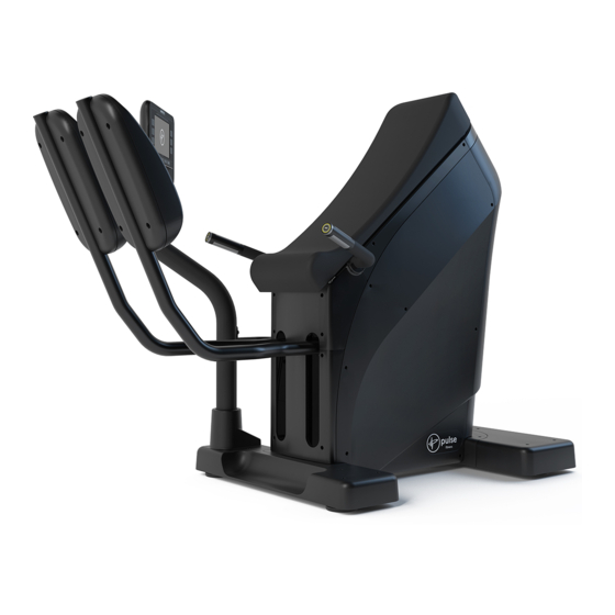
- Page 14 Machine Overview Console Stand Console Upholstery Resistance Adjuster Hand Sensor Hidden Transport Wheels Pedal Levelling Foot Pedal Arm...
- Page 15 Installation Instructions To install the machine, perform the following steps*: 1. Be careful unwrapping the machine and do not use a knife as it could damage the surface of the machine. 2. When moving the machine, a sufficient number of personnel should be used to prevent the equipment from collision, or to avoid injuries caused by personnel shortage.
- Page 16 Assembly Step 1 Steps Description Specifications Main Body Rear Leg Assembly Plain Washer Φ24*Φ13*2.5 Cap Head Socket Screw M12*65 Procedure: Connect the rear leg assembly. Loosely fix both bolts and washers, to line up the assemblies, then tighten. Note: This is a two person procedure. Tools Required : 10mm Allen Key...
- Page 17 Assembly Step 2 Steps Description Specifications Main Body Plain Washer Φ24*Φ13*2.5 Cap Head Socket Screw M12*65 Front Leg Assembly Procedure: Connect the front leg assembly. Loosely fix both bolts and washers, to line up the assemblies, then tighten. Note: This is a two person procedure. Tools Required : 10mm Allen Key...
- Page 18 Wiring Assembly Step 1 Steps Description Specifications Splice PCB 100-118-* Comms Comms Power Power COMMS POWER Procedure: Once the front leg is connected you will need to connect the Comms and Power cables to the Splice PCB.
- Page 19 Wiring Assembly Step 1 cont. Steps Description Specifications Splice PCB 100-118-* COAX NETWORK HANDPULSE Comms Comms Power Power Procedure: Then you will need to unravel the Network, Coax and Handpulse Cables and thread them through the console pipe.
- Page 20 Wiring Assembly Step 1 cont. Steps Description Specifications Splice PCB 100-118-* POWER COMMS Comms Comms Power Power Procedure: Next you need to make sure that the Power and Comms cables are fitted from the splice PCB and threaded through the console pipe. Note: This must all be connected BEFORE any mouldings are fitted onto the front leg, or you won’t be able to access the PCB without removing all mouldings..
- Page 21 Procedure: Connect the handlebars, make sure not to trap the hand-pulse sensor cables. The cables should pass through the connection hole and pass out thought the large hole situated on the main frame. Loosely fix both bolts and washers, to line up the assemblies, then add washers and nyloc bolts.
- Page 22 Wiring Assembly Step 2 Steps Description Specifications Interface PCB 100-244-* QUICK HAND Quick Quick CONTROL PULSE Hand Hand Control Control Pulse Pulse [+/-] [+/-] Ribbon Cable Ribbon Cable Procedure: Connect the Handpulse and Quick Control cables to the Interface PCB. Make sure that...
- Page 23 Assembly Step 4 Steps Description Specifications Main Body RH Leg Assembly LH Leg Assembly Plain Washer Φ21*Φ8*1.25 Spring Washer Φ18Φ8*2.2 Cap Head Socket Screw M8*30 Procedure: Insert the leg assembly Insert screws, check alignment and tighten. Note: This is a two person procedure. Tools Required : M8 Allen Key...
- Page 24 Assembly Step 5 Steps Description Specifications Main Body Pozi Pan Head Screw M5*20 Upper Front Cover Procedure: Slide the upper front cover into position. Insert screws, check alignment and tighten. Tools Required : Phillips Screwdriver...
- Page 25 Assembly Step 6 Steps Description Specifications Main Body Pozi Pan Head Screw M5*20 Lower Front Cover Procedure: Slide the lower front cover into position. Insert screws, check alignment and tighten. Tools Required : Phillips Screwdriver...
- Page 26 Wiring Assembly Step 3 Procedure: Thread the cables through the console pole. Make sure that you secure these at the top via an elastic band or cable tie to prevent them from slipping back down the neck. Make sure that the cables are not pulled tight, as you do not want to pull the plugs out of the sockets.
- Page 27 Assembly Step 7 Steps Description Specifications Main Body Plain Washer Φ21*Φ10.5*1.25 Cap Head Socket Screw M10*30 Front Foot Cover Console Pole Procedure: Slide the console pole cover up the console pole, so that it is out of the way of the bolt hole, making sure that the console cables do not get trapped and are threaded through the large hole and threaded underneath the front foot cover.
- Page 28 Assembly Step 8 Steps Description Specifications Main Body Front Foot Cover Pozi Pan Head Screw M5*20 Procedure: Slide the front foot cover into position over the front leg assembly. Insert screws, check alignment and tighten. Tools Required : Phillips Screwdriver...
-
Page 29: Table Of Contents
Assembly Step 9 Steps Description Specifications Main Body Plain Washer Φ21*Φ10.5*1.25 Cap Head Socket Screw M12*65 Console Pole Stabiliser Large Flat Washer Φ15*Φ5.3*1 21 22 Cap Head Socket Screw M5*20 Procedure: Attach the console pole stabiliser bar into position . insert screws, check alignment and tighten. - Page 30 Assembly Step 10 Steps Description Specifications Main Body Console* Socket Button Head Screw M6*10 Procedure: Attach the console to the console pole. Be careful not to trap any cables. The console can be wired once the console is connected in position. Tools Required : 4mm Allen Key.
- Page 31 Assembly Step 11 Steps Description Specifications Main Body Pozi Pan Head Screw M5*20 Rear Foot Cover Procedure: Fit the rear foot cover into position. Insert screws, check alignment and tighten. Note: Only fit the rear foot cover moulding once the machine is in the final location within the environment.
- Page 32 Assembly Step 12 Steps Description Specifications Main Body Pozi Pan Head Screw M5*15 Storage Tray Assembly Procedure: Fit the storage tray assembly. Make sure that it is in a straight alignment before fully tightening screws. Tools Required : Phillips Screwdriver...
- Page 33 Additional Wiring Information Steps Description Specifications Ribbon Extension PCB 100-247-* Ribbon Cable Comms Ribbon Cable Procedure: To replace the ribbon cable, use fingernails to open the clips to connect the ribbon to the PCB. Push clips closed to lock the ribbon in position.
- Page 34 Additional Wiring Information Steps Description Specifications LCB Assembly w/relay 100-283-* LCB Interface 100-198-* Cat5/RJ45 Female 100-287-* Connector with Panel Kit Round Rocker Switch 100-135-* Chassis mount 5 PIN DIN 100-185-* socket (NiPt) Coaxial Female- 100-254-* Female Adaptor...
- Page 35 Parts List Description Image Specifications Main Body Rear Leg Assembly Plain Washer Φ24*Φ13*2.5 2,2,4 Cap Head Socket Screw M12*65 Front Leg Assembly Cap Head Socket Screw M12*85 Nyloc Nut RH Handlebar Assembly LH Handlebar Assembly...
-
Page 36: Plain Washer Φ21*Φ10.5*1.25
Parts List Description Image Specifications RH Leg Assembly LH Leg Assembly Plain Washer Φ21*Φ10.5*1.25 Spring Washer Φ18Φ8*2.2 Cap Head Socket Screw M10*30 Pozi Pan Head Screw M5*20 3.5.4 Upper Front Cover... -
Page 37: Console Pole Stabiliser
Parts List Description Image Specifications Lower Front Cover Front Foot Cover Console Pole Console Pole Stabiliser Large Flat Washer Φ15*Φ5.3*1 Cap Head Socket Screw M5*20 Console Socket Button Head Screw M6*10 Rear Foot Cover... - Page 38 Parts List Description Image Specifications Pozi Pan Head Screw M5*20 Storage Tray Assembly 240-G29-* Plain Washer Φ21*Φ8*1.25 Cap Head Socket Screw M8x30...
- Page 39 Console Guide Using the Console Console 3.5 Console 5.0 (Series 1) (Series 2) Console 8.0 Console 6.0 (Series 3 10.1") (Series 3 18.5") For details on how to use each of the Series 1, 2 & 3 (10.1"/18.5") Consoles, refer to documents: 135-1379-* Series 1 (Console 3.5 CV) 135-1299-* Series 2 (Console 5.0 CV) 135-1300-* Series 3 (Console 6.0 CV) Cirrus V1...
- Page 40 Gym Wipes are large, durable pre-moistened wipes to use on the equipment before and after workouts. Use Gym Wipes on the equipment for at least 2 minutes for general disinfection purposes. Contact PULSE FITNESS Global Service Team to order these cleaners +44 (0)1260 294600 or email: global.service@pulsefitness.com. Compatible Cleaners DO NOT use water based solutions (on the following): Clean the display console, all exterior surfaces and the frame with a mild, non-abrasive silicon based household cleaner.
- Page 41 Clean the Console and all exterior surfaces with an appro WARNING: Failure to carry out maintenance on the equipment as per this manual could result in serious injury and void your warranty. Please ensure all publications supplied with PULSE FITNESS equipment are read and understood.
- Page 42 1. Verify the symptom and review the operating instructions. The problem may be unfamiliarity with the product and its features and workouts. 2. Locate and write down the serial number of the unit which is located on the front of the unit near the foot rail. 3. Contact Pulse Fitness Global Services Team.
- Page 43 Maintenance Schedule Daily Maintenance 1. Clean the frame with a silicone polish. 2. Clean with a mild soapy solution, handlebars and upholstery where applicable. 3. Clean the panels by spraying with cleaning foam, then wipe with a dry cloth. 4. General function test.
- Page 44 Maintenance Schedule Monthly Maintenance days 1. Vacuum around and under the machine. 2. Check loose fittings. 3. Check mains cables are not damaged.
- Page 45 Maintenance Schedule Return Spring 1. Remove side panel. 2. Internal mechanism and damaged spring. Replace spring to correct location, 4. Reattach side panel.
- Page 46 Failure to carry out maintenance on the equipment in this manual could result in serious injury and void your warranty. Please ensure all publications supplied with PULSE FITNESS equipment are read and understood. Replacement of defective components should be carried out IMMEDIATELY and/or keep the defective equipment out of use until repaired.
- Page 47 Company Addresses Global Corporate Headquarters Address: Pulse Fitness Ltd., Radnor Park, Greenfield Road, Congleton, Cheshire, CW12 4TW, England, United Kingdom Sales/Marketing: Tel: +44 (0)1260 294600 Fax: +44 (0)1260 299282 Email: info@pulsefitness.com Service: Tel: +44 (0)1260 294600 Email: global.service@pulsefitness.com Corporate Website: www.pulsefitness.com...
- Page 48 Pulse Fitness reserve the right to make changes to its products and services, where it considers necessary. © 2018 Pulse Fitness Ltd., a division of the Pulse Group of companies. All rights reserved. Pulse Fitness, is a registered trademark. Gym Wipes® is a registered trademark of The 2XL Corporation. PureGreen 24 is a trademark of Pure Green, LLC. Any use of these trademarks, without the express written consent of Pulse Fitness or the corresponding companies is forbidden.