Miele G 1 Series Technical Information
Hide thumbs
Also See for G 1 Series:
- Operating instructions manual (76 pages) ,
- Manual (46 pages) ,
- Operating instructions manual (76 pages)

Related Manuals for Miele G 1 Series


Summary of Contents for Miele G 1 Series
- Page 1 TECHNICAL INFORMATION G 1xxx and G 2xxx Dishwashers (All US Models) © 2012 Miele USA...
-
Page 2: Table Of Contents
G 1xxx/G 2xxx Technical Information Table of Contents A Warning and Safety Instructions ................12 1 General Information .................... 12 2 Touch Current Measurement ................12 3 Risk of Injury Due to Sharp Edges and Protruding Parts ........13 4 ... - Page 3 G 1xxx/G 2xxx Technical Information 3.7 G 2670 (Excella with Incognito) .............. 38 3.8 G 2872 (LaPerla II with Incognito) ............39 3.9 G 2830 (LaPerla with Navitronic) ............40 3.10 G 2832 (LaPerla II with Navitronic) ............41 4 ...
- Page 4 G 1xxx/G 2xxx Technical Information 4.2 Basket Guide Removal ................73 4.3 Toekick Removal ..................74 4.4 Steam Condenser Removal ..............74 4.5 Fan Removal ..................75 4.6 Connection Box Removal ............... 75 050 ...
- Page 5 G 1xxx/G 2xxx Technical Information 4.13 Removing the Circulation Pump ............106 4.14 Removing the Circulation Pump Housing Cap (with Ring Heater) ..107 4.15 Slide Shutter Removal (Excella/LaPerla) ..........108 4.16 D rive Removal (Excella/LaPerla) ............108 4.17 ...
- Page 6 G 1xxx/G 2xxx Technical Information 3.9 Fault Indications ................... 138 3.10 Fault Indication in Models with Software ID -769 ........138 3.11 Fault Code F01: Water/Heating NTC or Leads Short-Circuited .... 139 3.12 Fault Code F02: Water/Heating NTC or Leads Open-Circuited ....
- Page 7 G 1xxx/G 2xxx Technical Information 4.2.10 Excella - G 2630/G 2670 ..............197 4.2.11 Excella - G 2732 ................200 4.2.12 LaPerla - G 283x/G 2872 ..............203 4.2.13 Activating Dealer Demo Mode (Excella/LaPerla) ......207 ...
- Page 8 14 F11 Drainage Fault; Non-Return Valve ............. 237 15 G 2143; G 2472 Lower Spray Arms ..............237 16 Miele Policy on Dishwasher Detergent Requirements ........238 17 Dishwasher Detergents and Phosphates ............239 ...
- Page 9 G 1xxx/G 2xxx Technical Information Figure 020-5: Door Lock Latch, Position 1 ................52 Figure 020-6: Door Lock Latch, Position 2 ................53 Figure 020-7: Door Lock Latch, Position 3 ................54 Figure 020-8: Door Lock Latch, Intermediate Opening Position ..........55 Figure 020-9: Door Lock Latch, Intermediate Closing Position ..........
- Page 10 G 1xxx/G 2xxx Technical Information Figure 050-27: Filter Combination Lock/Unlock Positions ........... 115 Figure 050-28: Combination Filter Locking Clip (Unlocked) ..........116 Figure 050-29: Combination Filter Locking Clip (Locked) ........... 116 Figure 050-30: Filling the Salt Container in the Sump ............118 Figure 050-31: SIT Screws and Plug ..................
- Page 11 G 1xxx/G 2xxx Technical Information Table 080-10: Rinse Aid Settings, G 1202 ................173 Table 080-11: Service Programming Mode, G 1262 ............176 Table 080-12: Water Hardness Settings, G 1262 ............... 177 Table 080-13: Rinse Aid Settings, G 1262 ................177 Table 080-14: Service Programming Mode, G 1470/G 2470 ..........
-
Page 12: Warning And Safety Instructions
G 1xxx/G 2xxx Technical Information Warning and Safety Instructions General Information Danger! The low voltage produced in the electronic is not fully electrically isolated from the power supply. If power supply connection is via a reversible plug, and if this is reversed, then the live (phase) voltage is not applied to terminal [1] or [L] at the terminal block. -
Page 13: Risk Of Injury Due To Sharp Edges And Protruding Parts
Modification History When? Who? What? 2/17/2012 Jessica Naples Tech service bulletins added 8/22/2011 Jessica Naples Fault code F 78 corrected (page 160) Miele WaterProof System guarantee deleted 4/26/2011 Jessica Naples (page 79) 6/10/2010 Jessica Naples Updated 3/11/2010 Jessica Naples Updated... -
Page 14: C Technical Data
G 1xxx/G 2xxx Technical Information Technical Data Data Sheets Inspira, Inspira II Features Model G 1180 G 1182 G 2180 G 2182 G 2120 G 2140 G 2142 Width 24” Height Built-in 31.7” (adj. + 2.6”) 33.3” (adj.+ 2.6”) Sensor technology ECO sensor III Sensor softener Spray arm sensing... -
Page 15: Diamante, Diamante Plus
G 1xxx/G 2xxx Technical Information Diamante, Diamante Plus Features Model G 2143 G 2150 G 2183 Width 24” Height Free-standing Built-in 33.3” (adj.+ 2.6”) Sensor technology ECO sensor III Sensor softener Spray arm sensing None SensorDry Noise level 46dB 48dB 44dB Heater rating 1300W... -
Page 16: Optima, Optima Ii
G 1xxx/G 2xxx Technical Information Optima, Optima II Features Model G 1202 G 1262 G 147x G 2420 G 243x G 247x Width 18” 24” Height Free-standing 31.7” (adj. + 2.6”) Built-in 31.7” (adj. + 2.6”) 33.3” (adj. + 2.6”) Sensor technology Autosensor Sensor softener... -
Page 17: Excella, Excella Ii
G 1xxx/G 2xxx Technical Information Excella, Excella II Features Model G 2630 G 2670 G 2732 Width 24” Height Free-standing Built-in 33.3” (adj. + 2.6”) Sensor technology Autosensor Sensor softener Spray arm sensing Middle, bottom SensorDry Noise level 42dB Heater rating 1300W MPPW Circulation pump type... -
Page 18: Laperla, Laperla Ii
G 1xxx/G 2xxx Technical Information LaPerla, LaPerla II Features Model G 2830 G 2832 G 2872 Width 24” Height Free-standing Built-in 33.3” (adj. + 2.6”) Sensor technology Autosensor Sensor softener Spray arm sensing Middle, bottom SensorDry Noise level 42dB 41dB 40dB Heater rating 1300W... -
Page 19: Advanta
G 1xxx/G 2xxx Technical Information Advanta Features Model G 2020 G 2170 Width 24” Height Free-standing Built-in 33.3” (adj. + 2.6”) Sensor technology ECO sensor III Sensor softener Spray arm sensing None SensorDry Noise level 48dB Heater rating 1300W Circulation pump type MPEH (without slide shutter) Electrical connection 120VAC;... -
Page 20: Door Springs
G 1xxx/G 2xxx Technical Information Door Springs Summary Springs are always installed in pairs of the same tensile strength. Color Tensile Strength (lbs (N)) Length (in. (mm)) Orange Approx. 52 (230) 5.9 (150) Blue Approx. 65 (290) 6.2 (157) Uncolored Approx. -
Page 21: Door Springs Supplied As Spare Parts
G 1xxx/G 2xxx Technical Information Door Springs Supplied as Spare Parts Max. Front Panel Model Width Spring Color Weight [lbs (kg)] G 118x VI 24" Green 33.0 (15) G 1202 KST 18” Uncolored 27.5 (12.5) G 1202 EDST 18" Uncolored 25.3 (11.5) G 1262 VI 18”... -
Page 22: Hard-Wired Electrical Connection
G 1xxx/G 2xxx Technical Information Hard-Wired Electrical Connection Connect L1 (black) to L on the terminal block, N (white) to N on the terminal block, and GND to the ground connector. Note: Hardwiring the dishwasher should only be done if required by electrical code. Do not cut the plug off the power supply cord/plug and connect it directly to the house wiring under any circumstances. -
Page 23: D Layout Of Electrical Components
4 Salt LED and optical interface Touchtronic This series of Miele dishwashers is operated by pushing a single button – no separate temperature or drying selections – just turn the machine on, select a program and Miele does the rest. All models include a diverse group of wash programs for multiple cleaning needs. -
Page 24: Figure D-3: G 2120, G 214X, G 2150 Fascia Panel
G 1xxx/G 2xxx Technical Information Figure D-3: G 2120, G 214x, G 2150 Fascia Panel 1 Program selection LEDs 5 Intake/Drain LED 2 Program selection button 6 Rinse aid LED 3 Start/Stop button 7 Salt LED 4 Program sequence LEDs 8 On/Off button Figure D-4: G 2143 Fascia Panel 1 Program selection LEDs... -
Page 25: Incognito
Neither seen nor heard, the Miele Incognito Series OCI (Optical cycle Indicator) allows you to see the progress of the dishwasher cycle by way of a red light, which is steady or flashing depending on the status of the cycle. -
Page 26: Navitronic
G 1xxx/G 2xxx Technical Information Figure D-12: G 2670 Fascia Panel 1 Cursor buttons 4 i (Information) button 7 PC interface 2 C (clear) button 5 On button 8 Optical interface 3 Delay start button 6 Off button 9 RemoteVision Figure D-13: G 2872 Fascia Panel 1 Cursor buttons 4 i (Information) button... -
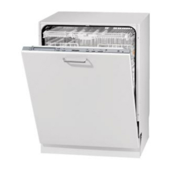
Page 27: Appliance Overviews
G 1xxx/G 2xxx Technical Information Appliance Overviews Integrated Models, Salt Container in Sump Figure D-15: Integrated Model with Salt Container in Sump 1 Upper spray arm (not visible) 7 Filter combination 2 Cutlery tray (model-dependent) 8 Data tag 3 Upper basket 9 Child safety lock in door handle (model-dependent) 4 Middle spray arm 10 Rinse aid reservoir... -
Page 28: Fully Integrated Models, Salt Container In Sump
G 1xxx/G 2xxx Technical Information Fully Integrated Models, Salt Container in Sump Figure D-16: Fully Integrated Model with Salt Container in Sump 1 Upper spray arm (not visible) 7 Filter combination 2 Cutlery tray (model-dependent) 8 Data tag 3 Upper basket 9 Optical interface 4 Middle spray arm 10 Rinse aid reservoir... -
Page 29: Integrated Models, Salt Container In Door
G 1xxx/G 2xxx Technical Information Integrated Models, Salt Container in Door Figure D-17: Integrated Model with Salt Container in Door 1 Upper spray arm (not visible) 7 Filter combination 2 Cutlery tray (model-dependent) 8 Data tag 3 Upper basket 9 Child safety lock in door handle (not visible) 4 Middle spray arm 10 Rinse aid reservoir 5 Air inlet for drying (model-dependent) -
Page 30: Fully Integrated Models, Salt Container In Door
G 1xxx/G 2xxx Technical Information Fully Integrated Models, Salt Container in Door Figure D-18: Fully Integrated Model with Salt Container in Door 1 Upper spray arm (not visible) 7 Filter combination 2 Cutlery tray 8 Data tag 3 Upper basket 9 Optical interface 4 Middle spray arm 10 Rinse aid reservoir... -
Page 31: Fully Integrated Models, No Salt Container (Slimline)
G 1xxx/G 2xxx Technical Information Fully Integrated Models, No Salt Container (Slimline) Figure D-19: Fully Integrated Model without Salt Container 1 Upper spray arm (not visible) 7 Filter combination 2 Cutlery tray 8 Data tag 3 Upper basket 9 Optical interface 4 Middle spray arm 10 Rinse aid reservoir 5 Air inlet for drying (model-dependent) -
Page 32: Component Layouts
G 1xxx/G 2xxx Technical Information Component Layouts G 2020 (Advanta with Novotronic) Figure D-20: G 2020 Component Layout Salt reed switch, B8/2 Turbidity sensor, B3/10 Salt container Main switch, S2 Reactivation solenoid, Y38 Heater pressure switch, B1/13 Wash-water hardness solenoid, Y5 Circulation pump (MPEH), M6 Heater relay, K1/1 Terminal block, X3/1... -
Page 33: G 1202, G 2120, G 214X, G 2150 (Optima Slimline, Inspira, Diamante With Touchtronic)
G 1xxx/G 2xxx Technical Information G 1202, G 2120, G 214x, G 2150 (Optima Slimline, Inspira, Diamante with Touchtronic) Figure D-21: G 1202, G 2120, G 214x, G 2150 Component Layout Salt float switch, B8/2 Main switch, S2 Salt container Heater pressure switch, B1/13 Reactivation solenoid, Y38 Circulation pump (MPEH), M6... -
Page 34: G 2420, G 243X (Optima Full-Size With Touchtronic)
G 1xxx/G 2xxx Technical Information G 2420, G 243x (Optima Full-Size with Touchtronic) Figure D-22: G 2420, G 243x Component Layout Salt float switch, B8/2 Turbidity sensor, B3/10 Salt reservoir Main switch, S2 Reactivation solenoid, Y38 Heater pressure switch, B1/13 Wash-water hardness solenoid, Y5 Circulation pump (MPEH), M6 Sensor softener, 10N1... -
Page 35: G 2630, G 2732 (Excella With Touchtronic)
G 1xxx/G 2xxx Technical Information G 2630, G 2732 (Excella with Touchtronic) Figure D-23: G 2630, G 2732 Component Layout Salt float switch, B8/2 Main switch, S2 Salt reservoir Heater pressure switch, B1/13 Reactivation solenoid, Y38 Slide shutter, M24 and B3/12 Wash-water hardness solenoid, Y5 Circulation pump (MPEW or MPPW), M6 Heater relay, K1/1... -
Page 36: G 1262, G 2170, G X18X (Optima Slimline, Advanta, Diamante, Inspira With Incognito)
G 1xxx/G 2xxx Technical Information G 1262, G 2170, G x18x (Optima Slimline, Advanta, Diamante, Inspira with Incognito) Figure D-24: G 1262, G 2170, G x18x Component Layout Salt float switch, B8/2 (not G 1262) Main switch, S2 Salt container (not G 1262) Heater pressure switch, B1/13 Reactivation solenoid, Y38 Circulation pump (MPEH), M6... -
Page 37: G X47X (Optima Full-Size With Incognito)
G 1xxx/G 2xxx Technical Information G x47x (Optima Full-Size with Incognito) Figure D-25: G x47x Component Layout Salt float switch, B8/2 Turbidity sensor, B3/10 Salt container Main switch, S2 Reactivation solenoid, Y38 Heater pressure switch, B1/13 Wash-water hardness solenoid, Y5 Circulation pump (MPEH), M6 Sensor softener, 10N1 Terminal block, X3/1... -
Page 38: G 2670 (Excella With Incognito)
G 1xxx/G 2xxx Technical Information G 2670 (Excella with Incognito) Figure D-26: G 2670 Component Layout (US only) 1 Salt float switch, B8/2 15 Main switch, S2 2 Salt container 16 Heater pressure switch, B1/13 3 Reactivation solenoid, Y38 17 Slide shutter, M24 and B3/12 4 Wash-water hardness solenoid, Y5 18 Circulation pump (MPEW), M6 5 Sensor softener, 10N1... -
Page 39: G 2872 (Laperla Ii With Incognito)
G 1xxx/G 2xxx Technical Information G 2872 (LaPerla II with Incognito) Figure D-27: G 2872 Component Layout Brine valve, Y60 RemoteVision, 3N1 Reactivation solenoid, Y38 Main switch, S2 Wash-water hardness solenoid, Y5 Salt float switch, B8/2 Sensor softener, 10N1 Heater pressure switch, B1/13 Heater relay, K1/1 Slide shutter, M24 and B3/12 Middle and bottom spray arm sensors,... -
Page 40: G 2830 (Laperla With Navitronic)
G 1xxx/G 2xxx Technical Information G 2830 (LaPerla with Navitronic) Figure D-28: G 2830 Component Layout 1 Brine valve, Y60 Main switch, S2 2 Reactivation solenoid, Y38 Salt float switch, B8/2 3 Wash-water hardness solenoid, Y5 Heater pressure switch, B1/13 4 Sensor softener, 10N1 Slide shutter, M24 and B3/12 5 Bottom spray arm sensor, 5N1... -
Page 41: G 2832 (Laperla Ii With Navitronic)
G 1xxx/G 2xxx Technical Information 3.10 G 2832 (LaPerla II with Navitronic) Figure D-29: G 2832 Component Layout Brine valve, Y60 RemoteVision, 3N1 Reactivation solenoid, Y38 Turbidity sensor, B3/10 Wash-water hardness solenoid, Y5 Main switch, S2 Sensor softener, 10N1 Salt float switch, B8/2 Bottom spray arm sensor, 5N1 Heater pressure switch, B1/13 Heater relay, K1/1... -
Page 42: Data Tag
G 1xxx/G 2xxx Technical Information Data Tag Figure D-30: Data Tag Location Figure D-31: Data Tag Information Model Numbering Figure D-32: Model Numbering... -
Page 43: Casing
G 1xxx/G 2xxx Technical Information Casing... -
Page 44: Service
G 1xxx/G 2xxx Technical Information Service Side Panel Removal 1. Remove the appropriate retaining screws (Figure 010-1, Item 1). 2. Use needlenose pliers to press in the retainer on the corner piece (Figure 010-1, Item 2). 3. Remove the side panel. Figure 010-1: Side Panel Removal... -
Page 45: Drip Pan Removal
G 1xxx/G 2xxx Technical Information Drip Pan Removal Warning! Before tilting the machine onto its back, open the salt container cap briefly, then close it firmly (this empties the water diverter). Then pump all water out of the cabinet. 1. Lay the dishwasher on its back. Ensure that the intake and drain hoses are not crushed. -
Page 46: Figure 010-3: Opening The Hinge Bracket
G 1xxx/G 2xxx Technical Information Figure 010-3: Opening the Hinge Bracket 7. Disconnect the ground connection. 8. Remove the cable clip from its guide. Warning! Machines with salt container in door: As there is brine in the salt container, have a means for collecting it on hand (bucket and cloth). 9. -
Page 47: Figure 010-5: Side Hinge Retaining Screw
G 1xxx/G 2xxx Technical Information Figure 010-5: Side Hinge Retaining Screw... -
Page 48: Door
G 1xxx/G 2xxx Technical Information Door... -
Page 49: Function
G 1xxx/G 2xxx Technical Information Function Door Handle and Door Lock (Novotronic/Touchtronic/Navitronic) To open the door, press the release catch inside the door grip. See Figure 020-1. Figure 020-1: Door Handle Release Note: If the door is opened during operation, the dishwasher will stop running. Once the door is closed the program will restart. -
Page 50: Door Lock (Incognito)
G 1xxx/G 2xxx Technical Information Door Lock (Incognito) The door lock is integrated in the electronic’s holder. Comfort Door Closing Aid (LaPerla II) The door lock latch on the machine is motorized. This is used to close the door automatically after it has been manually placed in the slightly open position (AutoClose function) and also to further improve drying performance with the Drying plus function by opening the door automatically at the end of a wash program. -
Page 51: Figure 020-4: Door Lock Latch
G 1xxx/G 2xxx Technical Information 1 Plug 1 2 Plug 2 Figure 020-4: Door Lock Latch The door lock latch can be set to 3 different positions via a DC motor (M23) (power supply approximately 16V, 10W). Positioning is controlled via the control-power module (SLT). -
Page 52: Figure 020-5: Door Lock Latch, Position 1
G 1xxx/G 2xxx Technical Information Position 1 - Door closed, latch completely retracted: To close the door, the door lock is locked and the latch is completely retracted. See Figure 020-5. Figure 020-5: Door Lock Latch, Position 1 1, 2, 3 Latch positions 1, 2, 3 4 Plug 2 5 Plug 1 S4 Door switch (supply voltage 120VAC), closed... -
Page 53: Figure 020-6: Door Lock Latch, Position 2
G 1xxx/G 2xxx Technical Information Position 2 - Door open, latch at mid-setting, loading/unloading position: If the door is opened, the door lock latch is moved from position 1 to position 2. The latch then extends by approximately 2.6 inches (6 centimeters) so that the door can be automatically closed again. -
Page 54: Figure 020-7: Door Lock Latch, Position 3
G 1xxx/G 2xxx Technical Information Position 3 - Drying, latch completely extended, Drying plus position: After the end of the wash sequence, the latch extends by approximately 3.5 inches (9 centimeters), but the door lock remains locked. See Figure 020-7. Figure 020-7: Door Lock Latch, Position 3 1, 2, 3 Latch positions 1, 2, 3 4 Plug 2... -
Page 55: Figure 020-8: Door Lock Latch, Intermediate Opening Position
G 1xxx/G 2xxx Technical Information Intermediate position, opening: Figure 020-8: Door Lock Latch, Intermediate Opening Position 1, 2, 3 Latch positions 1, 2, 3 4 Direction of latch movement 5 Plug 2 6 Plug 1 S4 Door switch (supply voltage 120VAC), open S80 Door movement switch (low voltage), open S24 Door contact switch (supply voltage 120VAC), closed M23 Door-locking motor (DC motor);... -
Page 56: Figure 020-9: Door Lock Latch, Intermediate Closing Position
G 1xxx/G 2xxx Technical Information Intermediate position, closing: Figure 020-9: Door Lock Latch, Intermediate Closing Position 1, 2, 3 Latch positions 1, 2, 3 4 Direction of latch movement 5 Plug 2 6 Plug 1 S4 Door switch (supply voltage 120VAC), open S80 Door movement switch (low voltage), open S24 Door contact switch (supply voltage 120VAC), open M23 Door-locking motor (DC motor);... -
Page 57: Combination Dispenser
G 1xxx/G 2xxx Technical Information Note: After a power failure, manual adjustment of the latch shaft, or servicing, it is possible that no clear position can be recognized. Irrespective of whether the control shaft is in an intermediate position or the position switch has not activated, the motor will be activated in the opening direction until a clear position is identified. -
Page 58: Fault Repair
G 1xxx/G 2xxx Technical Information Fault Repair Door Can’t Be Closed Cause: Locking bolt is in the wrong position (fully integrated models). Remedy: Activate the door lock emergency release; see Section 020-4.8. Cause: Incorrectly installed stopper at end of top basket guide. Remedy: Remove the stopper and install it correctly. -
Page 59: Service
G 1xxx/G 2xxx Technical Information Service Removing the Combination Dispenser 1. Remove the door outer panel. See Section 030-4.3. 2. Disconnect all dispenser plug connections. 3. Remove the retaining screws (Figure 020-11, Item 1). 4. Release the retaining clips (2 on top, 1 on bottom) and press out the dispenser assembly. -
Page 60: Bottom Door Seal Removal
G 1xxx/G 2xxx Technical Information 1. Open the door. 2. Loosen the flat round screw. 3. Adjust the locking plate as necessary. 4. Tighten the screw. Note: Adjust the locking plate so that the door seal is not excessively crushed and not under excess pressure when the door is closed (see Figure 020-12, Item A). -
Page 61: Door Lock Removal (Touchtronic/Novotronic/Navitronic)
G 1xxx/G 2xxx Technical Information Figure 020-13: Re-Installing the Door Seal Door Lock Removal (Touchtronic/Novotronic/Navitronic) 1. Remove the outer door panel (Section 030-4.3). 2. Remove the retaining screw (Figure 020-14, Item 1). 3. Press down the retaining lugs with a screwdriver (Figure 020-14, Item 2). 4. -
Page 62: Door Switch Replacement (Touchtronic/Novotronic/Navitronic)
G 1xxx/G 2xxx Technical Information Note: During reassembly, ensure that: 1. The protective foil is NOT pushed to one side or torn. 2. The foil tongue is positioned between the retaining bracket and door lock. 3. The foil is positioned under the plug area when the retaining bracket is re- installed. -
Page 63: Comfort Door Closing Aid (Ctsh) Removal (Laperla Ii)
G 1xxx/G 2xxx Technical Information Comfort Door Closing Aid (CTSH) Removal (LaPerla II) 1. Remove the top insulating mat. 2. Open the door. 3. Disconnect the plug connections. 4. Release the snap clip. 5. Pull the CTSH with adjustable door lock latch below the top door seal through towards the back. -
Page 64: Front Panel
G 1xxx/G 2xxx Technical Information Front Panel... -
Page 65: Service
G 1xxx/G 2xxx Technical Information Service Custom Door Panel (GDU) Removal 1. Remove the screw caps from the sides of the door (2 per side). 2. Support the panel while loosening the 4 screws; see Figure 030-1. 3. Lift/remove the panel from the appliance. Important: 1. -
Page 66: Door Outer Panel Removal
G 1xxx/G 2xxx Technical Information Door Outer Panel Removal Warning! Take care to hold and support the door outer panel when removing it. 1. Open the door and remove the countersunk screws (Figure 030-3, Item 2) around the inner edge. 2. -
Page 67: Lower Access Cover Plate Removal
G 1xxx/G 2xxx Technical Information Lower Access Cover Plate Removal 1. Remove the cover plate retaining screws; see Figure 030-4, Item 2. 2. Remove the cover plate. Figure 030-4: Lower Access Cover Plate Removal Connecting Strip Removal 1. Remove the drip pan; see Section 010-4.2. 2. -
Page 68: Inner Cabinet
G 1xxx/G 2xxx Technical Information Inner Cabinet... -
Page 69: Function
G 1xxx/G 2xxx Technical Information Function Cabinet Construction The inner cabinet is constructed of stainless steel (1.4301) welded onto four (4) vertical U-section sub-frames. The cabinet is sound- and heat-insulated with bitumen and/or mineral wool matting. Drying System Depending on model and production time frame, G 1xxx/G 2xxx machines may be equipped with version 1 or version 2 of recirculation Turbothermic drying. -
Page 70: Fan
G 1xxx/G 2xxx Technical Information condensation form, which deposit on the coldest places in the circuit. For dehumidification of the cabinet, moist air is extracted above the cutlery tray (front right) and directed into a condenser. This condenser is located in the right outer wall of the appliance and cool air from the exterior flows around it, thereby cooling the moist, warm cabinet air more quickly. -
Page 71: Fault Repair
G 1xxx/G 2xxx Technical Information sheeting, which serve as condensation surfaces. The second impeller transports the water vapor in the appliance to the condensation surfaces. In Version 2, a split-pole motor (approximately 19 watts) drives one impeller, which transports cool air to the outer surface of the right side panel. Fault Repair Condensation Forms on Adjacent Cabinets Symptom:... -
Page 72: Noises During Drying Cycle
G 1xxx/G 2xxx Technical Information Noises during Drying Cycle Symptom: After the fan is switched on, there may be noises during the drying cycle. Cause: Fan impeller not firmly mounted. Remedy: Replace the fan (see Section 040-4.5). Service Door Seal Replacement 1. -
Page 73: Basket Guide Removal
G 1xxx/G 2xxx Technical Information Basket Guide Removal 1. Open the door. 2. Remove the top basket. Warning! The basket guide must not be levered off in the area of the bolts (see Figure 040-4). This could result in damage to the cabinet walls. 3. -
Page 74: Toekick Removal
G 1xxx/G 2xxx Technical Information wall and the basket guide and remove the clip upwards. 5. Remove the basket guide. Note: If the clip is damaged during removal, it must be replaced. The clip can be ordered under mat. no. 01107900. Toekick Removal 1. -
Page 75: Fan Removal
G 1xxx/G 2xxx Technical Information Fan Removal 1. Remove the right side panel; see Section 010-4.1. 2. Remove the drip pan; see Section 010-4.2. 3. Remove the right-side toekick; see Section 040-4.3. 4. Disconnect all electrical connections to the fan. 5. -
Page 76: Figure 040-8: Connection Box
G 1xxx/G 2xxx Technical Information Figure 040-8: Connection Box Note: Position of the power cord may vary by model. -
Page 77: Water Paths
G 1xxx/G 2xxx Technical Information Water Paths... -
Page 78: Function
G 1xxx/G 2xxx Technical Information Function Water Circulation Figure 050-1: Water Paths - Diagram 1 Water intake solenoid Y2 13 Drain pump M8 2 Ball valve 14 Salt container 3 Water diverter 15 Ion replacement 4 Softener reactivation water reservoir 16 Reactivation solenoid Y38 5 Turbidity sensor B3/10 17 Intake from salt container... -
Page 79: Waterproof System (Wps)
G 1xxx/G 2xxx Technical Information WaterProof System (WPS) The WaterProof System (WPS) consists of a number of interdependent safety features to provide protection against water leakage. 1. Protection against solenoid valve leakage: Each water intake is controlled by an inlet valve. If this valve cannot close properly due to some defect or blockage by a foreign object, a second inlet valve ensures that the water supply is shut off. -
Page 80: Waterproof System Flow Rate Restrictor
G 1xxx/G 2xxx Technical Information WaterProof System Flow Rate Restrictor Figure 050-2: Flow Rate Restrictor 1 Rubber seal 2 Filter 3 Restrictor Water Diverter Water is taken into the appliance via the inlet valve and the water diverter, through the ion exchanger water softener into the sump. The water softener resin container is at the bottom of the water diverter. -
Page 81: Figure 050-3: Water Diverter
G 1xxx/G 2xxx Technical Information Detail View of Valves, Intakes and Outlets Figure 050-3: Water Diverter Flow meter B3/4 Water intake from salt container Ball valve Connection to inlet valve Softener reactivation water reservoir Reactivation valve Overflow EGS (water softener) valve Non-return device Water outlet to sump Vent... -
Page 82: Water Diverter Without Egs
G 1xxx/G 2xxx Technical Information 2.4.1 Water Diverter without EGS Figure 050-4: Water Diverter without EGS Water outlet to sump EGS valve not activated Reactivation valve Connection to inlet valve... -
Page 83: Water Diverter With Egs
G 1xxx/G 2xxx Technical Information 2.4.2 Water Diverter with EGS Figure 050-5: Water Diverter with EGS Water outlet to sump EGS valve activated Reactivation valve Connection to inlet valve... -
Page 84: Reactivation
G 1xxx/G 2xxx Technical Information 2.4.3 Reactivation Figure 050-6: Reactivation Water outlet to sump EGS valve Reactivation valve open Connection to inlet valve Note: Since machine no. 79575776 (6/5/07), the two connections between the water diverter and the salt container have each been fitted with 2 seals (O- rings);... -
Page 85: Water Softener Programming
G 1xxx/G 2xxx Technical Information 2.4.4 Water Softener Programming If your tap water hardness is above 8 grains per gallon (140 ppm), the water should be softened. If the water softener is needed (for select models only): The water softener sets automatically to the local water hardness. May use 3-in-1 tabs (these tabs contain detergent, rinse aid, and water softener salt). -
Page 86: Sensor Softener
G 1xxx/G 2xxx Technical Information system is not active as standard in all wash programs, but this can be programmed as an option if required. Sensor Softener If there is a break in data transfer between the sensor softener and the electronic module, the control activates an emergency program. -
Page 87: Mpeh Circulation Pump (No Slide Shutter Or Frequency Converter)
G 1xxx/G 2xxx Technical Information Warning! The 3 in 1 function may not be selected if the water hardness level is above 26 grains per gallon. The detergent manufacturer’s instructions must be followed. Note: When selecting 2 in 1 or 3 in 1, impulses dispense rinse aid (1 milliliter) to slowly empty the dispensing chamber. -
Page 88: Mpew Circulation Pump (With Slide Shutter, No Frequency Converter)
G 1xxx/G 2xxx Technical Information This pump is equipped with a winding changeover, which increases the torque at the moment it is switched on (higher starting torque). In this state the main winding is connected directly, and the auxiliary winding connected indirectly via the capacitor, to the power supply. -
Page 89: Mppw Circulation Pump (With Frequency Converter & Slide Shutter)
G 1xxx/G 2xxx Technical Information By monitoring the speed in this way and thus controlling additional water intake precisely can reduce energy and water consumption. The potential savings are approximately 15 percent water and 19 percent energy. Note: This system has an additional advantage. Good wash results are also ensured if the dishwasher load includes items with less than ideal shape (e.g., deep cups) as the controlled additional water intake will replace the water that may be trapped in such pieces. -
Page 90: Figure 050-10: Mppw Circulation Pump Voltages
G 1xxx/G 2xxx Technical Information Figure 050-10: MPPW Circulation Pump Voltages Note: These voltages can also be measured when the pump is not activated. The MPPW pump can be adjusted in various ways, enabling improved noise levels to be attained. Higher speeds can shorten program duration, if required;... -
Page 91: Heater Elements
G 1xxx/G 2xxx Technical Information Load sensing: Unlike the MPEW circulation pump, the MPPW version does not have a Hall sensor (B3/9) to measure speed of rotation. Instead of utilizing the Hall effect, the load is registered by monitoring the circulation pump current consumption as follows: During the water intake block, a certain fixed basic quantity of water is taken into the machine. -
Page 92: Ntc Temperature Sensor R30
G 1xxx/G 2xxx Technical Information Heater relay Heater pressure switch Heater element Electronic Figure 050-11: Heater Pressure Switch 2.14 NTC Temperature Sensor R30 Temperature sensor R30 (NTC resistor) is located in the bottom area of the sump. The electronic constantly monitors the current wash water temperature via the resistance of this sensor. -
Page 93: Turbidity Sensor (Eco Sensor Iii, Autosensor), B3/10
G 1xxx/G 2xxx Technical Information Temperature Sensor R30 Resistance Values Temperature (°F (°C)) Resistance (kΩ) 32 (0) 35.979 41 (5) 28.519 50 (10) 22.766 59 (15) 18.281 68 (20) 14.774 77 (25) 11.982 86 (30) 9.787 95 (35) 8.048 104 (40) 6.653 113 (45) 5.523... -
Page 94: Figure 050-12: Turbidity Sensor Circuit
G 1xxx/G 2xxx Technical Information accurately registered in the following measuring process. A photoelectric barrier switch (infrared (IR) diode opposite a phototransistor) acts as a turbidity sensor. Depending on the turbidity (transparency) of the water, a certain current flows through the phototransistor. This current is measured and processed by the electronic which then initiates the appropriate action. -
Page 95: Spray Arms
G 1xxx/G 2xxx Technical Information The flow rate is approximately 4 gallons (15 liters) per minute. In order to compensate for residues on the sensor and aging of the optical system, the turbidity sensor must be recalibrated regularly. This process is carried out automatically by the electronic and cannot be modified in any way. -
Page 96: Filter Combination With Microfine Filter
G 1xxx/G 2xxx Technical Information The maximum spray arm speed is approximately 50 revolutions per minute. Therefore, the next pulse can be registered at the earliest approximately 1.2 seconds after the start of the monitoring time. If a fault is indicated, the indication will remain active even after the door has been opened. -
Page 97: Drain Pump
G 1xxx/G 2xxx Technical Information suds flow through the microfine filter. Soil that is retained by the microfine filter either collects there or falls onto the filter cap where it will eventually be flushed out by the drain pump. The crown coarse filter (Figure 050-15, Item 1) is attached to the filter combination handle. -
Page 98: Fault Repair
G 1xxx/G 2xxx Technical Information Fault Repair Jammed Circulation Pump Symptom: With long intervals between wash cycles or at first commissioning (if the period of time between manufacture and installation was long), the axial face seal of the circulation pump can jam. As a result of this, the circulation pump will not run (see Fault Code F14, Section 080-3.16). -
Page 99: Foreign Object In Drain System
G 1xxx/G 2xxx Technical Information Foreign Object in Drain System Symptom: The drain pump or the non-return valve is blocked by a foreign object. Cause: Dishes were not, or were inadequately, cleaned. Remedy: Install the ring for the microfine filter, mat. no. 5672961 (refer to Figure 050-16). Figure 050-16: Microfine Filter Trap Note: Once the ring is installed, cleaning the filter has to be done in shorter... -
Page 100: Poor Drying Results
G 1xxx/G 2xxx Technical Information Poor Drying Results Symptom: Combination products are being used, and the “2in1” or “3in1” function is selected. Over time, the drying results deteriorate. Cause: All rinse aid remnants were flushed from the combi-dispenser (for background information, see Section 050-2.8). Thus only the rinse aid components of the combination product are available for the drying cycle. -
Page 101: Figure 050-17: Waterproof System
G 1xxx/G 2xxx Technical Information Figure 050-17: WaterProof System 2. Remove the restrictor (Figure 050-17, Item 3) with needlenose pliers (Figure 050-18). Figure 050-18: Removing the WaterProof System Restrictor 3. Install the new (green) restrictor using a suitable metric 5-millimeter socket wrench to press it firmly into place (Figure 050-19). -
Page 102: Waterproof System (Wps) Removal
G 1xxx/G 2xxx Technical Information Figure 050-19: Replacing the WaterProof System Restrictor 4. Re-install the filter and the seal. WaterProof System (WPS) Removal Note: Should the intake hose or water valves require replacement, the WPS must be replaced as a complete assembly. Individual replacement of the parts is not possible. -
Page 103: Removing The Middle Spray Arm
G 1xxx/G 2xxx Technical Information 2. Remove the top basket. 3. Unscrew the screw connection and remove the spray arm. Removing the Middle Spray Arm 1. Remove the top basket. 2. Unscrew the screw connection and remove the spray arm. Removing the Bottom Spray Arm 1. -
Page 104: Removing The Water Diverter With Resin Chamber
G 1xxx/G 2xxx Technical Information Figure 050-20: Spray Arm Sensor 4.10 Removing the Water Diverter with Resin Chamber 1. Unscrew the water diverter vent connection inside the cabinet. 2. Unscrew the salt container cap. - Page 105 G 1xxx/G 2xxx Technical Information 3. Remove the sealing ring. 4. Empty the salt container. 5. Close the opening with the service cap (mat. no. 06224660). 6. Unscrew the locknut. 7. Remove the left side panel (Section 010-4.1). Warning! The appliance must not be tilted onto its right side, as this would cause water to run into the fan.
-
Page 106: Removing Egs Solenoid Y5
G 1xxx/G 2xxx Technical Information 4.11 Removing EGS Solenoid Y5 1. Remove the left side panel (see Section 010-4.1). 2. Remove the drip pan. See Section 010-4.2. 3. Remove the connecting strip. See Section 030-4.5. 4. Remove the left toekick. See Section 040-4.3. 5. -
Page 107: Removing The Circulation Pump Housing Cap (With Ring Heater)
G 1xxx/G 2xxx Technical Information Important! During reassembly of the circulation pump ensure: 1. A new sealing ring is installed 2. The sealing ring is seated correctly in the pump housing cap 3. The pump housing cap is evenly seated 4. -
Page 108: Slide Shutter Removal (Excella/Laperla)
G 1xxx/G 2xxx Technical Information Warning! To prevent leakage problems, pay attention to the following during reassembly: 1. Check that the sealing ring is seated correctly in the pump housing cap. 2. When installing the pump housing cap, ensure that it is correctly seated. Line up the groove on the cap with the notch on the housing (if applicable). -
Page 109: Pump Impeller Removal
G 1xxx/G 2xxx Technical Information 2. Pump housing cap removal (Section 050-4.14). Slide shutter removal (Section 050-4.15). 4. Remove the drive retaining screws (Figure 050-23, Item 1). Figure 050-23: Drive Cam Warning! When re-installing, check that the O-ring is seated correctly on the drive cam. Before re-installing the slide shutter in the pump housing, make sure that the double tooth on the drive cog wheel points to the arrow on the housing. -
Page 110: Pump Capacitor Removal
G 1xxx/G 2xxx Technical Information 4.19 Pump Capacitor Removal 1. Remove the circulation pump; see Section 050-4.13. 2. Use a socket wrench to release the nut on the capacitor holder. 3. Remove the capacitor. 4. Disconnect its plug connections. 4.20 Removing the Heater Pressure Switch 1. -
Page 111: Removing The Sump
G 1xxx/G 2xxx Technical Information Figure 050-24: Removing the Drain Pump Note: When installing, apply a little water or soap solution to the pump seal as a lubricant. After installation, check all the pump fastening points. 4.23 Removing the Sump 1. -
Page 112: Removing The Ntc Temperature Sensor
G 1xxx/G 2xxx Technical Information Note: When installing, the following should be noted: 1. Install the sealing ring on the metal flange on the cabinet. 2. Apply liquid detergent as a lubricant to the outer surface of the seal. 3. Apply liquid detergent as a lubricant to the inside of the sump. 4. -
Page 113: Dismantling The Filter Combination
G 1xxx/G 2xxx Technical Information 6. Remove the drip pan. See Section 010-4.2. 7. Pull off the float switch. 8. Disconnect its plug connections. 4.27 Dismantling the Filter Combination Note: During reassembly, a locking piece must be installed to prevent the filter combination from falling apart;... -
Page 114: Filter Combination Assembly (New Microfine Filter And Handle)
G 1xxx/G 2xxx Technical Information 4.28 Filter Combination Assembly (New Microfine Filter and Handle) Note: During assembly, the dishwasher is used as a guide. If a new microfine filter and handle (crown coarse filter) are used, a locking piece is not required. 1. -
Page 115: Filter Combination Assembly (With Locking Piece)
G 1xxx/G 2xxx Technical Information Figure 050-27: Filter Combination Lock/Unlock Positions 4.29 Filter Combination Assembly (with Locking Piece) Note: During assembly, the dishwasher is used as a guide. 1. Install the microfine filter in the sump. Ensure that the lug is positioned towards the rear of the machine. -
Page 116: Figure 050-28: Combination Filter Locking Clip (Unlocked)
G 1xxx/G 2xxx Technical Information Figure 050-28: Combination Filter Locking Clip (Unlocked) Figure 050-29: Combination Filter Locking Clip (Locked) -
Page 117: Salt Container (In Sump) Removal
G 1xxx/G 2xxx Technical Information 4.30 Salt Container (in Sump) Removal 1. Remove the salt container cap from the cabinet interior. 2. Remove as much brine as possible from the salt container using a pump or cloth. 3. Remove the sealing ring. 4. -
Page 118: Filling The Salt Container In The Sump
G 1xxx/G 2xxx Technical Information 4.31 Filling the Salt Container in the Sump 1. Remove the lower basket and unscrew the salt container lid. Note: When opening the salt container, water will run out. Open the container only to refill salt. 2. -
Page 119: Salt Container In Door (Sit) Removal
G 1xxx/G 2xxx Technical Information 4.32 Salt Container in Door (SIT) Removal 1. Remove the door outer panel. See Section 010-4.1. 2. Remove the SIT retaining screws (see Figure 050-31, Item 1). 3. Remove the connection plug (reed switch) on the SIT (see Figure 050-31, Item 2). -
Page 120: Brine Valve (Y60) Removal
G 1xxx/G 2xxx Technical Information Note: When re-installing, the following must be complied with in order to prevent leakage problems: 1. Re-install the outer rubber seal. 2. Hook the guide clip in the bottom left area of the SIT behind the spacing strip. -
Page 121: Figure 050-32: Opening The Salt Container
G 1xxx/G 2xxx Technical Information Figure 050-32: Opening the Salt Container Note: When opening the salt container, water will run out. Open the container only to refill salt. 3. Before adding salt for the first time, fill the salt container with 2 quarts (2 liters) of water. -
Page 122: Water Level Check
G 1xxx/G 2xxx Technical Information Figure 050-34: Filling the Salt Container in the Door Warning! Inadvertently filling the salt container with dishwashing detergent will damage the water softener. Warning! Only use water softener salt specially formulated for dishwashers. Other salts may contain insoluble additives which can impair the water softener. 4.35 Water Level Check 1. -
Page 123: Electronic
G 1xxx/G 2xxx Technical Information Electronic Novotronic and Touchtronic Incognito Navitronic... -
Page 124: Function
G 1xxx/G 2xxx Technical Information Function General Operation 2.1.1 Novotronic Controls 1. Make sure that the spray arms are not blocked. 2. Close the door. 3. Turn on the dishwasher. The “Start” indicator will flash. 4. Select a wash program by turning the program selector switch to the left or right. -
Page 125: Incognito Controls
G 1xxx/G 2xxx Technical Information Figure 080-3: Selected Options 10. When finished customizing the program, confirm with OK. 11. Select Start. 2.1.3 Incognito Controls 1. Make sure that the spray arms are not blocked. 2. Turn on the dishwasher by touching the I control. 3. -
Page 126: Test Sequence And Background Information
G 1xxx/G 2xxx Technical Information 2.2.1 Test Sequence and Background Information Note: In x14x models, the "Rinse" LED will flash corresponding to the test step (e.g., one quick flash for test step 1, one slow flash and one quick flash for step 11, etc.). - Page 127 G 1xxx/G 2xxx Technical Information 7. M24, M6, slide shutter at middle spray arm setting with circulation pump: The slide shutter is activated and set to the middle spray arm setting. The circulation pump is then operated for 30 seconds at the maximum speed for controlled operation.
-
Page 128: Machine Response Following A Power Failure
G 1xxx/G 2xxx Technical Information seconds. (Models with spray-arm sensing only.) 17. 5N1, M6, wash sequence with bottom spray arm sensor (mini-program): This starts with 30 seconds of drainage which begins with pulsed priming (2 seconds on/2 seconds off). The water inlet valve is then activated (on models with and without slide shutter) until 1.4 gallons (5.4 liters) has been taken in. -
Page 129: Dishes Can Be Added" Function (Laperla Ii)
G 1xxx/G 2xxx Technical Information (the focus here is on the protection of glassware, and the increased wash and rinse temperatures would contradict this) or the Energy Saver program (resource-saving washing is the key aspect here and the increased energy consumption in the Turbo function would contradict this). -
Page 130: Drying Plus Function (Laperla Ii)
G 1xxx/G 2xxx Technical Information temperature to be reached. Heater performance always remains at a constant level, but every additional item in the load binds more heat energy and this extends the heating time. The SensorDry function can affect certain parameters as follows: Final rinse temperature: The final rinse temperature lies in the temperature range of 144 to 158°F, depending on the situation. -
Page 131: Figure 080-6: Drying Phase (Before Program End)
G 1xxx/G 2xxx Technical Information Figure 080-6: Drying Phase (Before Program End) Figure 080-7: Drying Plus (After Program End) After the Drying plus cycle has completed, the motorized door lock latch moves from position 3 (drying, latch completely extended) back to position 2 (door open, latch positioned in the center). -
Page 132: Dealer Demo Mode (Excella/Laperla)
G 1xxx/G 2xxx Technical Information opened at any time. Note: The customer can deactivate the Drying plus function in the Settings menu. Drying plus is inoperative in the following programs: Rinse & Hold Express Glassware cold Glassware warm Dealer Demo Mode (Excella/LaPerla) The appliance is equipped with three or five different demo programs (depending on model) for the dealer. -
Page 133: Table 080-1: Electronics Id Summary
G 1xxx/G 2xxx Technical Information ID Number Modification Date Models (and Modules) Affected -1092 series modification. G 1470, G 2470, G 2420, G 2430 -1304 Start of series. G 1202, G 1262 -1404 Start of series. G 2732, G 2832, G 2872 (SLT -1405 Start of series. -
Page 134: Programming Of Language And Time Of Day At First Commissioning (Excella/Laperla)
G 1xxx/G 2xxx Technical Information 2.10 Programming of Language and Time of Day at First Commissioning (Excella/LaPerla) At first commissioning or after replacing the electronic, a welcome message will appear in the display. Subsequently, the language, time format and time of day must be set as described in the operating instructions. -
Page 135: Program Interrupted, No Fault Indication
G 1xxx/G 2xxx Technical Information Cause: Incorrect positioning of adjustable door lock latch prevents the door contact switch from closing. Remedy: Reset the adjustable door lock latch. Cause: Door seal incorrectly seated, preventing the door contact switch from closing. Remedy: Check the door seal seating and adjust as necessary. -
Page 136: Settings Selected During Initial Commissioning Are Not Saved
G 1xxx/G 2xxx Technical Information Quit the machine service mode or briefly disconnect the machine from the power supply again or log on the machine to the RemoteVision system. After a maximum of 1 minute, the RemoteVision system can be used again. Settings Selected During Initial Commissioning Are Not Saved Symptom: After successful initial commissioning, settings that have been made (such... -
Page 137: Fault Code Summary
G 1xxx/G 2xxx Technical Information Fault Code Summary Note: Not all fault codes apply to all model numbers. Fault Code Possible Fault No fault registered F01 (see Section 080-3.11) Water/heating NTC or leads short-circuited F02 (see Section 080-3.12) Water/heating NTC or leads open-circuited F11 (see Section 080-3.13) Drainage fault F12 (see Section 080-3.14) -
Page 138: Fault Indications
G 1xxx/G 2xxx Technical Information Fault Indications Model Fault Indication At the end of the program cycle, with the door open, all program LEDs flash. G x17x, G x18x The buzzer sounds for two minutes. “SaniWash” LED flashes, e.g., 1x quickly for F01. “Intake/Drain”... -
Page 139: Fault Code F01: Water/Heating Ntc Or Leads Short-Circuited
G 1xxx/G 2xxx Technical Information off and on, the Wash/Rinse LED is not activated. As soon as the next water intake has taken place, the display functions normally. 4. Fault indication after low voltage has been registered (Integrated models) If low voltage is registered during a program in operation, the Start/Stop LED flashes briefly and then switches off for 10 seconds. -
Page 140: Fault Code F11: Drainage Fault
G 1xxx/G 2xxx Technical Information 3.13 Fault Code F11: Drainage Fault Symptom: Water present in appliance and is not being drained off. See Table 080-3 for model-specific fault indications. Background information: After each drain pump step, the circulation pump operates for 2 seconds and heater pressure switch B1/13 checks the water level. -
Page 141: Fault Code F12: Water Intake Fault At Start Of Step
G 1xxx/G 2xxx Technical Information specialist. If water does not flow from the drain hose, then check the filters. 1. Clean the on-site drain. 2. Check the sump drain. 3. Check the filters for blockage. 4. Check the heater pressure switch and replace it if necessary. See Section 050-4.20 Cause: Ball in non-return valve in sump has not opened (e.g., jammed). - Page 142 G 1xxx/G 2xxx Technical Information second intervals for one hour. The drain pump will also be activated at intervals to prevent the possibility of the appliance overflowing. All other components remain inactive. If these attempts to achieve the minimum pulse rate fail, the buzzer is activated for 2 minutes.
-
Page 143: Fault Code F13: Water Intake Fault At End Of Step
G 1xxx/G 2xxx Technical Information 5. Remove the filter with needlenose pliers. 6. Clean or replace the filter as necessary. See Section 050-4.1. Cause: Water inlet valve defective. Remedy: Check the water inlet valve for proper operation by performing the following steps: 1. - Page 144 G 1xxx/G 2xxx Technical Information Cause: Flow meter B3/4 is providing too few pulses. Remedy: 1. Check WPS valve Y2 (filter, restrictor disc). 2. Remove the left side panel (Section 010-4.1). 3. Check that the plate with the reed switch on flow meter B3/4 is seated correctly.
-
Page 145: Fault Code F14: Water Intake Fault: Heater Pressure Switch
G 1xxx/G 2xxx Technical Information (mounted on the left toekick) for power. If power is present, then check the connectors and wiring. If not, then go to the next step. 5. Check for power coming off of the electronic board. If no power, then replace the electronic board. - Page 146 G 1xxx/G 2xxx Technical Information Cause: Heater pressure switch B1/13 defective or blocked by foreign objects. Remedy: 1. Check the heater pressure switch. 2. Check the connection plug and wiring harness. 3. Replace the heater pressure switch, if necessary. See Section 050-4.20. Cause: Circulation pump inoperative.
-
Page 147: Fault Code F15: Water Intake Fault - Hot Water
G 1xxx/G 2xxx Technical Information 5. Using a multimeter, place the probes onto the heater pressure switch sensing leads off of connector ST5 on the electronic board. During circulation pump operation you should read no voltage at these points. If 120VAC is measured, replace the heater pressure switch (Section 050-4.20). -
Page 148: Fault Code F19: Flow Meter B3/4 Stiff And Not Turning Freely
G 1xxx/G 2xxx Technical Information 3.19 Fault Code F19: Flow Meter B3/4 Stiff and Not Turning Freely Symptom: The program is interrupted and the drain pump is operated. See Table 080-3 for model-specific fault indications. Background information: Satisfactory test routines to monitor free rotation of the flow meter impeller could not be established. -
Page 149: Fault Code F24: Heater Relay Contact
G 1xxx/G 2xxx Technical Information Measuring time for 0.26 gallons (one liter) Test routine successful; water intake time is extended. Test routine unsuccessful; fault code F19 is registered. a. During the first step, water intake solenoid Y2 is activated in order to let another 0.52 gallons (2 liters) flow into the machine. -
Page 150: Figure 080-11: Circuit Test Path For F24
G 1xxx/G 2xxx Technical Information Background information: Figure 080-11: Circuit Test Path for F24 18 seconds after starting the drain sequence, the electronic will perform an operational test on the heater relay. The circulation pump is not operating and no power is applied to the heater relay coil. If 120VAC is registered at ST5 on the electronic board, then an F24 is logged in memory (see Figure 080-11). -
Page 151: Fault Code F25: Target Temperature Fault
G 1xxx/G 2xxx Technical Information 3.21 Fault Code F25: Target Temperature Fault Symptom: See Table 080-3 for model-specific fault indications. Background information: During the heating stage, the desired temperature has not been reached within the given time (minimum 75 minutes). In subsequent wash blocks, after this fault has been registered, the heater is not activated and no rinse aid is dispensed. -
Page 152: Fault Code F32: Door Lock Does Not Close
G 1xxx/G 2xxx Technical Information Cause (ID nos. -1404, -1465 only): Faulty position monitoring of the comfort door closing aid (CTSH). For a switched-off appliance, the door-closing function is in operation. Under adverse conditions, the locking system can stop in a faulty position. The control electronic recognizes this as a “zero position”... -
Page 153: Fault Code F36: Door Lock Switch Defective
G 1xxx/G 2xxx Technical Information 3.25 Fault Code F36: Door Lock Switch Defective Symptom: The drain pump is operated, and any running program is interrupted. See Table 080-3 for model-specific fault indications. Cause: S4 and S80 closed at the same time. Remedy: Replace the comfort door closing aid;... -
Page 154: Fault Code F51: Heater Pressure Switch
G 1xxx/G 2xxx Technical Information 3.29 Fault Code F51: Heater Pressure Switch Symptom: The program is interrupted and the drain pump is operated. See Table 080-3 for model-specific fault indications. Background information: Start position: Figure 080-12: Circuit Test Path for F51 (Initial State) One second after program start, heater relay K1/1 is activated. -
Page 155: Fault Code F52: Heater Pressure Switch Has Reset During Heating
G 1xxx/G 2xxx Technical Information Cause: Heater relay solenoid defective. Remedy: Replace the heater relay. Cause: Connection from heater relay to electronic is open-circuited. Remedy: 1. Check plug connections. Ensure that all plug connections are clean and secure. 2. Check the connection wires for continuity. Cause: Heater pressure switch open- or short-circuited. -
Page 156: Fault Code F53: Speed Sensor Fault
G 1xxx/G 2xxx Technical Information Remedy: Check the dispensed quantities of detergent and rinse aid. Follow the information given in the operating instructions. Note: A check should also be made to ensure that the type of detergent matches the setting made. When, for example, combination products (2-in-1 or 3-in-1 tablets) are used but the Tab type has not been set, rinse aid will be dispensed twice. -
Page 157: Fault Code F63: Slide Shutter Fault
G 1xxx/G 2xxx Technical Information 3.32 Fault Code F63: Slide Shutter Fault Symptom: If this fault is registered, the program is not interrupted. The fault will only be indicated when the fault code memory is checked in the service mode. Background information: Even though the slide shutter motor has been activated, there is no signal change at the position switch. -
Page 158: Fault Code F68: Circulation Pump Operating After Shutoff
G 1xxx/G 2xxx Technical Information Cause: Circulation pump stiff and not turning freely. Remedy: Clean the circulation pump and remove any foreign objects that may be present. Cause: Speed sensor defective. Remedy: Replace the speed sensor; see Section 050-4.21. Cause: Circulation pump capacitor defective. -
Page 159: Fault Code F70: Float Switch Fault
G 1xxx/G 2xxx Technical Information checked. For this, the heater relay must have been activated and both electronic’s inputs must be potential-free. Cause: Heater pressure switch defective. Remedy: Replace the heater pressure switch. See Section 050-4.20. Cause: Heater relay defective. Remedy: Replace the heater relay. -
Page 160: Fault Code F78: Circulation Pump Fault
G 1xxx/G 2xxx Technical Information Note: If the leak source has not yet been detected, check the following areas in the toekick and the drip pan for wear and tear: Connection between the circulation pump and the sump Axial face seal of the circulation pump Connection between the drain pump and the sump Connection between the salt container and the water intake Connection between the water intake and the cabinet side wall... -
Page 161: Fault Code F79: Circulation Pump Interaction Fault
G 1xxx/G 2xxx Technical Information Remedy: Replace the circulation pump. See Section 050-4.13. 3.38 Fault Code F79: Circulation Pump Interaction Fault Symptom: The program is interrupted and the drain pump is operated. See Table 080-3 for other model-specific fault indications. Cause: Faulty interaction between the frequency converter electronic of the circulation pump and the electronic (SLT). -
Page 162: Fault Code F85: Slide Shutter Signal Change Fault
G 1xxx/G 2xxx Technical Information Cause: Turbidity sensor connection wires open-circuited. Remedy: Check the connection wires for continuity. 3.40 Fault Code F85: Slide Shutter Signal Change Fault Symptom: Even though the slide shutter has not been activated, a signal change has been detected at the position switch. -
Page 163: Fault Code F87: Sensor Softener Fault
G 1xxx/G 2xxx Technical Information Cause: Magnet missing. Remedy: Replace the salt container lid. Cause: Reed switch magnet defective. Remedy: Replace the reed switch magnet. 3.42 Fault Code F87: Sensor Softener Fault Symptom: If this fault is registered, the program is not interrupted. The fault will only be indicated when the fault code memory is checked in the service mode. -
Page 164: Fault Code F91: Load Size Registration Inactive
G 1xxx/G 2xxx Technical Information Remedy: Check for foreign objects in the measurement path. Remove blockage or replace feed pipe (Section 050-4.7) if necessary. Cause: Turbidity sensor connection wires open-circuited. Remedy: Check connections to electronic board and turbidity sensor B3/10 and perform a continuity check. -
Page 165: Table 080-4: Customer Programming Summary
G 1xxx/G 2xxx Technical Information Model Access Procedure Available Options 1. Press and hold Program button. Water hardness G 118x/G 2170/G 218x 2. Switch on appliance and wait Rinse aid approx. 4 sec. for “Rinse & Hold” (See Section 4.2.1 for option Buzzer on/off LED to light up. -
Page 166: Service Programming
G 1xxx/G 2xxx Technical Information Service Programming 4.2.1 Inspira and Advanta - G 118x/G 2170/G 218x Initial requirements: 1. Open the door. 2. Switch off the appliance. Accessing: 1. Press and hold the Program button. 2. Switch on the appliance. 3. - Page 167 G 1xxx/G 2xxx Technical Information Function Programming Display Briefly press the Program button 4x. To make the desired setting, press and The "Intake/Drain" LED flashes 4x hold the Program button rapidly at intervals. "SaniWash" until the "Intake/Drain" Buzzer on/off LED is off: Buzzer on (standard LED lights up.
-
Page 168: Table 080-5: Service Programming Mode Summary, G 118X/G 2170/G 218X
G 1xxx/G 2xxx Technical Information Function Programming Display The "Intake/Drain" LED flashes Press the Program button 2x slowly and 7x rapidly. 27x. To make the desired "SaniWash" LED is off: Standard setting, press and hold the Activating/deactivating setting; "SaniWash" LED flashes: Program button until the improved drying Improved drying –... -
Page 169: Optima - G 1202
G 1xxx/G 2xxx Technical Information Flash Pattern of Water Hardness [°d] Water Hardness [gpg] "SaniWash" LED 1 – 4 1.1 – 4.3 1x rapidly 5 – 7 5.4 – 7.5 2x rapidly 8 – 11 8.6 – 11.8 3x rapidly 12 –... - Page 170 G 1xxx/G 2xxx Technical Information Options: Function Programming Display "Rinse" LED is out or flashes. The Do not press the Delay display shows the software version Software version ID check Start button. The "Delay ID no. in consecutive digits Start" LED is not lit. (e.g., -1304).
- Page 171 G 1xxx/G 2xxx Technical Information Function Programming Display The "Rinse" LED is out or flashes. The display shows p and a digit Press the Delay Start alternately. Setting options: p0 = button 20x. The "Delay Standard setting; p1 = Wash Start"...
-
Page 172: Table 080-8: Service Programming Mode, G 1202
G 1xxx/G 2xxx Technical Information Function Programming Display Press the Delay Start button 35x. The "Delay Start" LED flashes 3x The "Rinse" LED is off or flashes. The display shows p and a digit slowly and 5x rapidly Appliance width setting intermittently. -
Page 173: Optima - G 1262
G 1xxx/G 2xxx Technical Information Water Hardness [°d] Water Hardness [gpg] Display … … … 38.5 37 – 50 39.6 – 53.5 51 – 60 54.6 – 64.2 61 – 70 65.3 – 74.9 Table 080-9: Water Hardness Settings, G 1202 Rinse Aid Volume [mL] Display Table 080-10: Rinse Aid Settings, G 1202... - Page 174 G 1xxx/G 2xxx Technical Information Options: Function Programming Display The display shows the software Do not press the Tab version ID no. in consecutive digits Software version ID check button. The "Tab" LED is not lit. (e.g., -1304). This programmable function can be used to reset all modifiable Press the Tab button 1x.
- Page 175 G 1xxx/G 2xxx Technical Information Function Programming Display The display shows p and a digit alternately. Setting options: p0 = Press the Tab button 20x. Standard setting; p1 = Wash The "Tab" LED flashes 2x Adjusting the main wash temperature increased. If this option slowly.
-
Page 176: Table 080-11: Service Programming Mode, G 1262
G 1xxx/G 2xxx Technical Information Function Programming Display Press the Tab button 35x. The "Tab" LED flashes 3x slowly and 5x rapidly The display shows p and a digit Appliance width setting intermittently. Press the alternately. Setting options: p0 = Program button as 24”... -
Page 177: Optima - G 1470/G 2470
G 1xxx/G 2xxx Technical Information Water Hardness [°d] Water Hardness [gpg] Display … … … 38.5 37 – 50 39.6 – 53.5 51 – 60 54.6 – 64.2 61 – 70 65.3 – 74.9 Table 080-12: Water Hardness Settings, G 1262 Rinse Aid Volume [mL] Display Table 080-13: Rinse Aid Settings, G 1262... - Page 178 G 1xxx/G 2xxx Technical Information Options: Note: In models with software version ID –769, wait for the decimal point in the display to switch off before pressing the GEL button. Function Programming Display Do not press the GEL The display shows the software Software version ID check button.
- Page 179 G 1xxx/G 2xxx Technical Information Function Programming Display This programmable function can be Press the GEL button 12x. used to reset all customer-modified The “GEL” LED flashes parameters back to their standard Resetting standard once slowly and 2x quickly settings. The display shows P and a settings intermittently.
-
Page 180: Table 080-14: Service Programming Mode, G 1470/G 2470
G 1xxx/G 2xxx Technical Information Function Programming Display Press the GEL button 26x. The “GEL” LED flashes 2x The display shows p and a digit slowly and 6x quickly Second interim rinse (ID alternately. Setting options: p0 = intermittently. Press the nos. -
Page 181: Optima - G 1472/G 2472
G 1xxx/G 2xxx Technical Information Water Hardness [°d] Water Hardness [gpg] Display … … … 38.5 37 – 50 39.6 – 53.5 51 – 60 54.6 – 64.2 61 – 70 65.3 – 74.9 Table 080-15: Water Hardness Settings, G 1470/G 2470 Note: If the dishwasher is connected to an external ion exchanger water softener (i.e. - Page 182 G 1xxx/G 2xxx Technical Information Function Programming Display Press the options button The display shows p and the digit/s 2x. The “Tab” LED flashes of the set value alternately. p0 = Softener sensor activation/ 2x quickly intermittently. Softener sensor active. Hardness Water hardness setting Press the Program button setting range: p1 to p70;...
- Page 183 G 1xxx/G 2xxx Technical Information Function Programming Display Press the options button The display shows p and a digit 22x. The “Tab” LED alternately. Setting options: p0 = Program running time flashes 2x slowly and 2x Standard setting; p1 = Program reduction quickly intermittently.
-
Page 184: Advanta - G 2020
G 1xxx/G 2xxx Technical Information Function Programming Display Press the options button The display shows p and a digit 39x. The “Tab” LED alternately. The following countries flashes 3x slowly and 9x can be set: p1 = EUR (Europe); p2 = Country setting quickly intermittently. - Page 185 G 1xxx/G 2xxx Technical Information 3. Release the Start/Stop button. 4. Immediately press the Start/Stop button 5 times; on the 5th time, hold until the "Start/Stop" LED flashes. 5. Release the Start/Stop button. 6. If the "Start/Stop" LED does not light up, repeat the procedure. Acknowledgement indicator: The "Start/Stop"...
-
Page 186: Table 080-18: Service Programming Mode Summary, G 2020
G 1xxx/G 2xxx Technical Information Function Programming Display "Rinse" LED is off = program Press the Start/Stop running time per factory setting; button 3x.Turn the selector "Rinse" LED flashes = shortened Shortening program switch to 6 o'clock. To program running time. Program- sequence change the setting, press dependent shortcut due to a... -
Page 187: Inspira And Diamante - G 2120/G 2140/G 2150
G 1xxx/G 2xxx Technical Information Flash Pattern of "Rinse" Water Hardness [°d] Water Hardness [gpg] 1 – 4 1.1 – 4.3 1x rapidly 5 – 7 5.4 – 7.5 2x rapidly 8 – 11 8.6 – 11.8 3x rapidly 12 – 15 12.8 –... - Page 188 G 1xxx/G 2xxx Technical Information Options: Function Programming Display The "Rinse & Hold" LED flashes 1x Press the Program rapidly. "Rinse" LED is off: Values button 1x. Press the Reset do not correspond to standard Start/Stop button to settings; "Rinse" LED flashes: reset all standard Values correspond to standard settings.
-
Page 189: Table 080-21: Service Programming Mode Summary, G 2120/G 2140/G 2150
G 1xxx/G 2xxx Technical Information Function Programming Display The "Rinse & Hold" LED flashes Press the Program 2x slowly and 7x rapidly. "Rinse" button 27x. Press the LED is off: Standard setting; "Rinse" Activating/deactivating Start/Stop button as LED flashes: Improved drying – improved drying appropriate to make the depending on the program, drying... -
Page 190: Inspira And Diamante - G 2142/G 2143
G 1xxx/G 2xxx Technical Information Rinse Aid Volume [mL] Flash Pattern of "Rinse" LED — 1x rapidly 2x rapidly 3x rapidly 4x rapidly 5x rapidly 6x rapidly Table 080-23: Rinse Aid Quantities, G 2120/G 2140/G 2150 One milliliter equals 0.3 fluid ounces. Standard setting. - Page 191 G 1xxx/G 2xxx Technical Information Function Programming Display Press the Program (or The "Rinse & Hold" LED flashes 3x Delay Start for G 2143) rapidly. If the "Rinse" LED flashes Dispensed rinse aid button 3x. Press the 3x rapidly, this corresponds to quantity setting Start/Stop button as standard setting of 0.1 fl.oz.
-
Page 192: Table 080-24: Service Programming Mode Summary, G 2142/G 2143
G 1xxx/G 2xxx Technical Information Function Programming Display Press the Program (or The "Rinse & Hold" LED flashes 3x Delay Start for G 2143) slowly and 6x rapidly. "Rinse" LED button 36x. Press the Appliance height setting is off: Standard appliance height (G Start/Stop button as 1xxx);... -
Page 193: Optima - G 2420/G 243X
G 1xxx/G 2xxx Technical Information Rinse Aid Volume [mL] Flash Pattern of "Rinse" LED — 1x rapidly 2x rapidly 3x rapidly 4x rapidly 5x rapidly 6x rapidly Table 080-26: Rinse Aid Quantities, G 2142/G 2143 One milliliter equals 30 fluid ounces. Standard setting. - Page 194 G 1xxx/G 2xxx Technical Information Function Programming Display Press the Delay Start The "Rinse" LED is out or flashes. button 2x. The “Delay The display shows p and the digit/s Start” LED flashes 2x Softener sensor activation/ of the set value alternately. p0 = quickly intermittently.
- Page 195 G 1xxx/G 2xxx Technical Information Function Programming Display The "Rinse" LED is out or flashes. Press the Delay Start The display shows p and a digit button 21x. The “Delay alternately. Setting options: p0 = Start” LED flashes 2x Final rinse temperature Standard setting;...
-
Page 196: Table 080-27: Service Programming Mode, G 2420/G 243X
G 1xxx/G 2xxx Technical Information Function Programming Display Press the Delay Start button 27x. The “Delay The "Rinse" LED is off or flashes. Start” LED flashes 2x The display shows p and a digit slowly and 7x quickly Extended drying time alternately. -
Page 197: Excella - G 2630/G 2670
G 1xxx/G 2xxx Technical Information Water Hardness [°d] Water Hardness [gpg] Display … … … 38.5 37 – 50 39.6 – 53.5 51 – 60 54.6 – 64.2 61 – 70 65.3 – 74.9 Table 080-28: Water Hardness Settings, G 2420/G 243x Note: If the dishwasher is connected to an external ion exchanger water softener (i.e. - Page 198 G 1xxx/G 2xxx Technical Information Function Programming Display Select Reset. To restore Reset the standard settings, The display reads Reset factory select OK. To return to the default settings? main menu, press Back. The display lists the languages that Select Language. can be selected.
- Page 199 G 1xxx/G 2xxx Technical Information Function Programming Display This function is activated in the Select Save extras. standard settings. In the display, Save extras Select a setting and this is signaled with the message confirm with OK. On. If you do not wish to save, select Off.
-
Page 200: Excella - G 2732
G 1xxx/G 2xxx Technical Information Function Programming Display Select 2nd interim rinse. Second interim rinse Select a setting and Options: On, Off (standard setting). confirm with OK. Select Machine height. Options: Normal (G 1xxx), Machine height setting Select a setting and XXL (G 2xxx). - Page 201 G 1xxx/G 2xxx Technical Information Options: Function Programming Display Select Reset. To restore the Reset standard settings, select OK. The display reads Reset standard To return to the main menu, settings? press Back. The display lists the languages that Select Language. can be selected.
- Page 202 G 1xxx/G 2xxx Technical Information Function Programming Display This function is deactivated as Select System lock. Select Activating/deactivating standard. This is indicated in the a setting and confirm with the system lock display by Off. If the function is desired, select On. Setting the temperature Select Temperature.
-
Page 203: Laperla - G 283X/G 2872
G 1xxx/G 2xxx Technical Information Function Programming Display Select 2nd interim rinse. Second interim rinse Select a setting; confirm with Options: On, Off (standard setting). SC (with or without Options On, Off. Select SC. Make a selection cutlery tray) - available Programming function not available and confirm with OK. - Page 204 G 1xxx/G 2xxx Technical Information Options: Note: Some of the following parameters can also be programmed via the Settings menu. Function Programming Display Select Reset. To restore Reset the standard settings, The display reads Reset standard select OK. To return to the settings? main menu, press Back.
- Page 205 G 1xxx/G 2xxx Technical Information Function Programming Display Select Change main menu. Select a wash program for position 1, The display shows the programs press Continue, and do available. The order of the first Changing the main menu exactly the same for three can be modified.
-
Page 206: Table 080-31: Service Programming Mode, G 283X/G 2872
G 1xxx/G 2xxx Technical Information Function Programming Display Select Factory default. To reset the parameters Resetting standard The display reads Reset to (settings) modified by the settings standard settings? customer to their standard settings, confirm with OK. Select Temperature. Select Main wash or Final Options: Normal and Increased. -
Page 207: Activating Dealer Demo Mode (Excella/Laperla)
G 1xxx/G 2xxx Technical Information 4.2.13 Activating Dealer Demo Mode (Excella/LaPerla) 1. Access the service programming mode. 2. Select Dealer, then OK. The display shows the following options: Demo mode: The program is activated by pressing a button. It runs through once and must then be restarted. -
Page 208: Service Mode
G 1xxx/G 2xxx Technical Information Service Mode 4.3.1 Inspira and Advanta - G 118x/G 2170/G 218x Initial requirements: 1. Open the door. 2. Switch off the appliance. Accessing: 1. Press and hold the Program button. 2. Switch on the appliance. 3. -
Page 209: Optima - G 1202
G 1xxx/G 2xxx Technical Information Function Programming Display Press the Program button The "Intake/Drain" LED flashes 3x 3x. To display the rapidly. The "SaniWash" LED’s operating hours, press and flash pattern indicates the saved Operating hours check hold the Program button operating hours: Each slow flash of until the "Intake/Drain"... -
Page 210: Optima - G 1262
G 1xxx/G 2xxx Technical Information Options: Function Programming Display "Rinse" LED is out or flashes. The Do not press the Delay Software version ID display shows the software version Start button. The "Delay check ID no. in consecutive digits Start" LED is not lit. (e.g., -1304). -
Page 211: Optima - G 1470/G 2470
G 1xxx/G 2xxx Technical Information Options: Function Programming Display Do not press the Tab The display shows the software Software version ID button. The "Tab" LED is version ID no. in consecutive digits check not lit. (e.g., -1304). Press the Tab button 1x. The "Tab"... -
Page 212: Optima - G 1472/G 2472
G 1xxx/G 2xxx Technical Information Options: Note: In models with software version ID –769, wait for the decimal point in the display to switch off before pressing the GEL button. Function Programming Display Do not press the GEL The display shows the software Software version ID check button. -
Page 213: Advanta - G 2020
G 1xxx/G 2xxx Technical Information 5. Release the Program button. 6. If the “Rinse & Hold” LED does not light up, repeat the procedure. Acknowledgement indicator: The “Rinse & Hold” LED flashes slowly (1 flash per second). Options: Function Programming Display Do not press the options The display shows the software... -
Page 214: Inspira And Diamante - G 2120/G 214X/G 2150
G 1xxx/G 2xxx Technical Information until the "Start/Stop" LED flashes. 5. Release the Start/Stop button. 6. If the "Start/Stop" LED does not light up, repeat the procedure. Acknowledgement indicator: The "Start/Stop" LED flashes slowly (1 flash per second). Options: Function Programming Display Turn the selector switch to... -
Page 215: Optima - G 2420/G 243X
G 1xxx/G 2xxx Technical Information 4. Immediately press the Start/Stop button 3 times; on the 3rd time, hold until the "Start/Stop" LED flashes. 5. Release the Start/Stop button. 6. If the "Start/Stop" LED does not light up, repeat the procedure. Acknowledgement indicator: The "Start/Stop"... -
Page 216: Excella - G 2630/G 2670
G 1xxx/G 2xxx Technical Information until the "Start/Stop" LED flashes. 5. Release the Start/Stop button. 6. If the "Start/Stop" LED does not light up, repeat the procedure. Acknowledgement indicator: The "Start/Stop" LED flashes slowly (1 flash per second). Options: Function Programming Display "Rinse"... -
Page 217: Table 080-40: Service Mode Summary, G 2630/G 2670
G 1xxx/G 2xxx Technical Information 3. Release the C (clear) button when the display lights up. 4. Immediately press the C (clear) button 3 times; on the 3rd time, hold for at least 4 seconds. Acknowledgement indicator: Successful accessing of the programming mode is indicated by the LEDs, which are all off, and Service program, in the top line of the display. -
Page 218: Excella - G 2732
G 1xxx/G 2xxx Technical Information 4.3.10 Excella - G 2732 Initial requirements: 1. Close the door. 2. Switch off the appliance. Accessing: 1. Press and hold the Start button. 2. Switch on the appliance. 3. Release the Start button when the display lights up. 4. -
Page 219: Table 080-42: Service Mode Summary, G 283X/G 2872
G 1xxx/G 2xxx Technical Information 4.3.11 LaPerla - G 283x/G 2872 Initial requirements: 1. Close the door (open for G 2872). 2. Switch off the appliance. Accessing: 1. Press and hold the C (clear) button. 2. Switch on the appliance. 3. -
Page 220: Fascia Panel
G 1xxx/G 2xxx Technical Information Fascia Panel Navitronic Touchtronic Incognito... -
Page 221: Fault Repair
G 1xxx/G 2xxx Technical Information Fault Repair On/Off Button Jams Symptom: In machines with plastic panels, the On/Off button can get stuck. Cause: Cutout in panel for switch is too narrow. Remedy: Cutout was modified in machines 79249108 and later. In older machines, use an appropriate tool to widen the cutout. -
Page 222: Service
G 1xxx/G 2xxx Technical Information Service Fascia Panel Removal (Touchtronic/Novotronic/Navitronic) 1. Open the door. 2. Remove the retaining screws (Figure 100-1, Item 1). 3. Remove the fascia panel. 4. Pull off the switch buttons and selector knob (if applicable). 5. Disconnect the plug connection to the main electronic module. Figure 100-1: Screws Securing the Fascia Panel (Touchtronic/Novotronic/Navitronic) To re-install, first install the fascia panel and screw it into position, then restore the switch buttons and knob. -
Page 223: Fascia Panel Removal (Incognito)
G 1xxx/G 2xxx Technical Information Fascia Panel Removal (Incognito) 1. Remove the retaining screws (Figure 100-2, Item 1). 2. Slide the fascia panel upwards. Figure 100-2: Fascia Panel Removal (Incognito) Note: When re-installing, care must be taken with the following: The fascia must be installed before the switch buttons. -
Page 224: Electronic Removal (Incognito)
G 1xxx/G 2xxx Technical Information Note: If the dishwasher has a furniture front, insert a towel or similar between its top edge and the fascia to prevent the risk of scratching. 3. Disconnect all plugs. 4. Press in the retaining lugs; see Figure 100-3, Item 1. 5. -
Page 225: Electronic Removal (Touchtronic/Novotronic)
G 1xxx/G 2xxx Technical Information Electronic Removal (Touchtronic/Novotronic) 1. Fascia panel removal (Section 100-4.1). Note: If the dishwasher has a slanted fascia, the door outer panel must also be removed; see Section 030-4.3. 2. Remove the screws from the sides of the door inner panel. 3. -
Page 226: Cutlery Tray
G 1xxx/G 2xxx Technical Information Cutlery Tray... -
Page 227: Fault Repair
G 1xxx/G 2xxx Technical Information Fault Repair Water Droplets on the Cutlery Tray Symptom: Excessive amount of water droplets on the cutlery tray after program has finished. Cause: Water clings as a result of using a combination detergent. Remedy: Replace honeycomb-patterned inserts with inserts having a grid pattern. Note: The following inserts are available: Insert 1/1: Mat. -
Page 228: Technical Service Bulletins
Problem: In rare installations, an intermittent buzzing or vibrating noise is emanating from the dishwasher. This is possibly associated with the startup cycle of the circulation pump. Miele dishwashers are engineered for their quietness through all cycle phases. Cause: At the moment when the circulation pump starts, the lower edge of the metal front cover plate may be sympathetically vibrating where it meets the bottom pan. -
Page 229: Changing The Door Handle Style On A Dishwasher Delivered As 'Sf' (Pre-Finished)
“Automatic” is appropriate. Pos 24 Sensor softener = Automatic or 1 – 70 (Manual hardness setting) Alternatively, these settings can be accessed via the Miele Diagnostic Support software. These instructions are also included with the replacement electronic. Changing the Door Handle Style on a Dishwasher Delivered as ‘SF’... - Page 230 G 1xxx/G 2xxx Technical Information Panel Mounting Screws Remove the existing handle. Lay the panel face down on a soft surface and remove the two hex nuts with a 10mm nut driver. The existing handle will come off with the mounting studs attached.
-
Page 231: Re-Designed Cutlery Trays Are Now Available For G 2000 Series Dishwashers231
G 1xxx/G 2xxx Technical Information Re-Designed Cutlery Trays Are Now Available for G 2000 Series Dishwashers In some cases, the honeycomb design of the cutlery tray would retain water droplets causing the dishes in the racks below to get wet. The G 2002 series cutlery trays have been modified with an ‘angular’... -
Page 232: Some F13 Faults In The G 2000 Dishwashers May Be Caused By A Clogged Flow Restrictor
G 1xxx/G 2xxx Technical Information dishwasher, the following procedure must be adhered to: 1. Unplug the dishwasher from the wall outlet. Using the house circuit breaker to cut power is also an option. (Turning the power off via the front panel control is not sufficient.) 2. - Page 233 G 1xxx/G 2xxx Technical Information Step 5: Remove drip tray and place off to side. Step 6: Remove hoses from the water intake jacket/water softener resin tank located on left side of dishwasher having a pan or such available to catch raining water. Hoses are depicted by #40 and #120 on exploded view of water intake included below Step 7: Allow water to drain from blue water intake hose.
-
Page 234: G 2000 Circulation Pumps Have A New Speed Sensor Configuration
G 1xxx/G 2xxx Technical Information G 2000 Circulation Pumps Have a New Speed Sensor Configuration Two G 2000 MPEW circulation pumps, part numbers 6770655 and 6770605, have a new speed sensor configuration. The speed sensor is no longer a renewable part, and is sealed into the pump housing. The wiring is brought out to a Molex connector on the side of the housing. -
Page 235: G 2000 Dishwashers In Vacation Homes: F14, F69, Or All Leds Blink
G 1xxx/G 2xxx Technical Information G 2000 Dishwashers in Vacation Homes: F14, F69, or All LEDs Blink When G 2000 dishwashers are left idle for several months (as in a summer or vacation home), there is a possibility that the residual water in the sump may evaporate;... -
Page 236: Update; Replacing The Waterproof Hose In A Dishwasher
G 1xxx/G 2xxx Technical Information (MPPW). Primarily, LaPerla and Excella models, G 28x2 and G 27x2, are equipped with these pumps. The F79 fault is documented as a circulation pump communications error. This fault does not appear on all machines at all times. There is no reason to replace any electronics or pumps. -
Page 237: F11 Drainage Fault; Non-Return Valve
G 1xxx/G 2xxx Technical Information F11 Drainage Fault; Non-Return Valve G 2000 – G 5000 dishwashers: When diagnosing a drainage fault, F11, or intake-drain condition, one of the components that should be inspected is the non-return valve. Routinely, we would check to see that the valve is free of blockages and that the steel ball moves freely. -
Page 238: Miele Policy On Dishwasher Detergent Requirements
2005 and continuing today, we suggest that powders, tablets, gels, and gelpacs can be used effectively in all of our dishwashers. (In fact, in support of this effort, Miele is now selling our own brand of tablets that can be found at our online store.) Effective immediately, please begin offering the updated information for all detergent inquiries. -
Page 239: Dishwasher Detergents And Phosphates
G 1xxx/G 2xxx Technical Information Dishwasher Detergents and Phosphates Dishwasher detergents no longer contain phosphates In March 2006, Washington State became the first state in the nation to ban phosphates from dishwasher detergents. By 2010, 15 other states adopted this policy and enacted similar bans. Faced with this growing dilemma, the major dishwasher detergent manufacturers agreed to stop producing phosphate-laden detergents by July 2010. - Page 240 G 1xxx/G 2xxx Technical Information http://www.appliance.net/2010/states-ban-phosphate-laden-dishwasher-soap- 1988 http://pressroom.consumerreports.org/pressroom/2010/08/low-phosphate- dishwasher-detergents-that-work.html...