Garmin GI 275 Pilot's Manual
Hide thumbs
Also See for GI 275:
- Installation manual (531 pages) ,
- Pilot's manual (332 pages) ,
- Maintenance manual (120 pages)
Table of Contents
Advertisement
Quick Links
Advertisement
Table of Contents
Troubleshooting

Related Manuals for Garmin GI 275


Summary of Contents for Garmin GI 275
- Page 1 GI 275 ™ Pilot’s Guide...
- Page 3 SYSTEM OVERVIEW FLIGHT INSTRUMENTS NAVIGATION HAZARD AVOIDANCE AUTOPILOT ADDITIONAL FEATURES APPENDICES INDEX...
- Page 5 Garmin. Garmin hereby grants permission to download a single copy of this manual and of any revision to this manual onto a hard...
- Page 6 WARNING: Do not rely on the displayed minimum safe altitude (MSAs) as the sole source of obstacle and terrain avoidance information. Always refer to current aeronautical charts for appropriate minimum clearance altitudes. Garmin GI 275 Pilot's Guide 190-02246-01 Rev. A...
- Page 7 70° North latitude between longitude 85° E and 114° E. (Northern Russia); South of 55° South latitude between longitude 120° E and 165° E. (Region south of Australia and New Zealand). 190-02246-01 Rev. A Garmin GI 275 Pilot's Guide...
- Page 8 WARNING: Do not use the Garmin SVT runway depiction as the sole means for determining the proximity of the aircraft to the runway or for maintaining the proper approach path angle during landing.
- Page 9 The traffic and own ship symbols are an abstract representation and do not reflect the physical extent of the aircraft/traffic, and should not replace other methods for identifying traffic. 190-02246-01 Rev. A Garmin GI 275 Pilot's Guide...
- Page 10 Navigation Database coding specific to each procedure. NOTE: The FAA has asked Garmin to remind pilots who fly with Garmin database- dependent avionics of the following: • It is the pilot’s responsibility to remain familiar with all FAA regulatory and advisory guidance and information related to the use of databases in the National Airspace System.
- Page 11 The database exclusion list can be viewed at flygarmin.com by selecting ‘Database Exclusions List.’ NOTE: The pilot/operator must have access to Garmin and Jeppesen database alerts and consider their impact on the intended aircraft operation. The database alerts can be viewed at flygarmin.com by selecting ‘Aviation Database Alerts.’...
- Page 12 Warnings, Cautions & Notes Blank Page Garmin GI 275 Pilot's Guide 190-02246-01 Rev. A...
- Page 13 Software remain with Garmin and/or its third-party providers. You acknowledge that the Software is the property of Garmin and/or its third-party providers and is protected under the United States of America copyright laws and international copyright treaties. You further acknowledge that...
- Page 14 Software License Agreement Blank Page Garmin GI 275 Pilot's Guide 190-02246-01 Rev. A...
- Page 15 Record of Revisions Page Part Number Rev. Date Description Range 190-02246-01 September, 2019 Production Release 190-02246-01 Rev. A Garmin GI 275 Pilot's Guide...
- Page 16 Record of Revisions Blank Page Garmin GI 275 Pilot's Guide 190-02246-01 Rev. A...
-
Page 17: Table Of Contents
1.5 ACCESSING SYSTEM FUNCTIONALITY .............. 16 System Settings ........................16 1.6 DISPLAY BACKLIGHTING .................. 20 1.7 DEVICE REGISTRATION ..................20 1.8 WIRELESS CONNECTIVITY (GARMIN CONNEXT) ..........21 Bluetooth Setup ........................21 Managing Paired Devices ....................24 1.9 DATABASES ...................... 25 Automatic Database Updates ..................... - Page 18 3.3 EIS PAGES ......................60 Main Page ..........................60 AUX Page ..........................62 EGT Page ..........................63 CHT Page ..........................66 Fuel Page ..........................67 3.4 ABNORMAL OPERATIONS ................. 69 EIS Alerts ..........................69 Garmin GI 275 Pilot's Guide 190-02246-01 Rev. A...
- Page 19 Terrain Alerts ........................145 Terrain Inhibit........................149 Terrain Status ........................150 Synthetic Vision Terrain ..................... 151 5.5 TRAFFIC ......................151 Display of Traffic Information ................... 152 Traffic Data by Source ......................158 190-02246-01 Rev. A Garmin GI 275 Pilot's Guide...
- Page 20 SECTION 8 APPENDICES ................193 APPENDIX A: ANNUNCIATIONS AND ALERTS ............193 Alert Level Definitions ....................... 193 System Messages ....................... 195 APPENDIX B: DATABASE INFORMATION .............. 201 Available Databases ......................202 Database Troubleshooting Tips ..................203 Garmin GI 275 Pilot's Guide 190-02246-01 Rev. A...
- Page 21 Table of Contents APPENDIX C: AVIATION TERMS AND ACRONYMS ..........205 APPENDIX D: DISPLAY SYMBOLS ................. 219 VFR Symbols ........................219 IFR Symbols ......................... 220 Airspace Symbols ....................... 221 INDEX ........................I-1 190-02246-01 Rev. A Garmin GI 275 Pilot's Guide...
- Page 22 Table of Contents Blank Page Garmin GI 275 Pilot's Guide 190-02246-01 Rev. A...
-
Page 23: Section 1 System Overview
Depictions of equipment may differ slightly from the actual equipment. 1.1 INSTRUMENT DESCRIPTION The GI 275 Multi-Function Instrument (MFI) is a highly configurable drop-in upgrade for many traditional round-gauge instruments. The MFI can relay information to and process data from compatible devices in the following categories: •... -
Page 24: Unit Types And Configurations
To act as an attitude indicator, the basic MFI must have an external AHRS source. To display air data, the basic MFI must have an external air data computer. To show magnetic heading, all MFIs must have an external magnetometer. Garmin GI 275 Pilot's Guide 190-02246-01 Rev. A... -
Page 25: Unit Configurations
The Inner Knob can be pushed. All operations are done with the knobs or touchscreen. The touchscreen can be operated with bare fingers or gloves made for capacitive touchscreens. 190-02246-01 Rev. A Garmin GI 275 Pilot's Guide... -
Page 26: Touchscreen
Button Outer Knob Button Inner Knob GI 275 Controls ('HSI Map' Page) TOUCHSCREEN Gestures Touch is touching the screen briefly with a single finger. Touch A touch can select a menu, activate a command key or data entry field, display map feature information, or select a button. -
Page 27: Page Navigation
Touching data field buttons will either display a pop-up window from which a selection can be made or display a keypad to supply the data. See the Data Entry discussion in this section for more information. Data Field Button 190-02246-01 Rev. A Garmin GI 275 Pilot's Guide... -
Page 28: Page Menus
It may be necessary to open menus to access specific features. Opening the menu: With any page displayed, swipe up starting at the bottom of the screen. With any page displayed, push and hold the Inner Knob. Garmin GI 275 Pilot's Guide 190-02246-01 Rev. A... -
Page 29: Menu Navigation
2) Touch the desired letters and/or numbers. 3) To enter a negative number, first input the positive value. Then, touch the +/- Button to toggle the negative sign. 4) Touch the Enter Button to save input. 190-02246-01 Rev. A Garmin GI 275 Pilot's Guide... -
Page 30: Operation
CAUTION: Do not clean display surfaces with abrasive cloths or cleaners containing ammonia. They will harm the anti-reflective coating. INSTRUMENT POWER APPLICATION Depending on the installation and aircraft electrical system, MFIs can be powered by either the aircraft's Battery or Avionics master. Garmin GI 275 Pilot's Guide 190-02246-01 Rev. A... -
Page 31: Normal Operation
(another MFI, G500/600 TXi, etc.) have a fault, the unit exclusively behaves as a Primary ADI until the fault is resolved. Alternatively, the crew can manually select reversionary operation modes from panel-mounted switches. 190-02246-01 Rev. A Garmin GI 275 Pilot's Guide... -
Page 32: System Annunciations
If multiple MFIs are installed, each unit will independently generate its own messages; messages are not synchronized across units. Thus, the flight crew must acknowledge messages on each MFI. Message Alert Indicator Garmin GI 275 Pilot's Guide 190-02246-01 Rev. A... -
Page 33: Backup Battery
Manual for legal flight under IFR. Battery 'Menu' The 'Battery Status' Screen displays: » Remaining battery charge % » Time to full charge (if charging) » Minimum battery backup time » Battery status (temperature, voltage, current) 190-02246-01 Rev. A Garmin GI 275 Pilot's Guide... -
Page 34: Adahrs Operation (Optional)
MFI with information from its internal sensors or interconnected external sensors. Attitude and heading information are updated on the 'ADI' Page and heading data on the 'HSI' Page and 'HSI Map' Page. Garmin GI 275 Pilot's Guide 190-02246-01 Rev. A... - Page 35 1) From the 'ADI' Page, open the menu. 2) Select the ADI Options or Options Button. 3) Select the Sensors Button. 4) Select the AHRS or ADC Button, then the desired AHRS or ADC source. 190-02246-01 Rev. A Garmin GI 275 Pilot's Guide...
-
Page 36: Vfr Gps Receiver Operation
• Acquiring Satellites—Receiver is looking for and collecting data from satellites visible at its last known or initialized location but has not acquired a fix. • 2D Nav—At least three satellites have been acquired and a two-dimensional location fix has been calculated. Garmin GI 275 Pilot's Guide 190-02246-01 Rev. A... - Page 37 The progress of satellite acquisition is shown as indicated by signal bar appearance: • No bar—Receiver is looking for a satellite • Green bar—Receiver has found the indicated satellite VFR GPS Satellite Signals 190-02246-01 Rev. A Garmin GI 275 Pilot's Guide...
-
Page 38: Accessing System Functionality
Creating a Crew Profile: 1) From the 'Crew Profile' Screen, select New. 2) Input a Crew Profile name (up to 8 characters). 3) Touch the Enter Button or push the Inner Knob. Garmin GI 275 Pilot's Guide 190-02246-01 Rev. A... - Page 39 5) If a duplicate profile name exists, an "Export profile (profile name)? Export will overwrite any profile on the storage device with this name." message appears. Select the OK Button. 6) An "Export Successful!" message appears. Select the OK Button. 190-02246-01 Rev. A Garmin GI 275 Pilot's Guide...
- Page 40 3) Confirm deletion by selecting the OK Button. Date/Time The MFI will automatically set system time from GPS or connected compatible Garmin devices. By default, system time is displayed in UTC (also called Zulu Time). If there is no GPS time source, it is possible to manually set the date and time.
- Page 41 2) Select the desired units of measure (inHg, hPa, or mb). NOTE: Altitude unit adjustments do not affect altimeter display units. Contact a Garmin dealer or installer for altimeter unit adjustment. Contact a Garmin Dealer or installer for unit adjustment.
-
Page 42: Display Backlighting
1.7 DEVICE REGISTRATION Unregistered MFIs cannot install critical databases or updates. To register the MFI, create a Garmin account at flygarmin.com and add the MFI as a device on the account. Before registering the MFI, obtain the System ID of the MFI. -
Page 43: Wireless Connectivity (Garmin Connext)
1.8 WIRELESS CONNECTIVITY (GARMIN CONNEXT) The MFI has built-in Wi-Fi and Bluetooth capabilities. Connext allows for a wireless connection between the MFI and a Personal Electronic Device (PED) running the Garmin Pilot application and provides up-to-date information throughout the cockpit. - Page 44 3) Select the Pair a Device Button. The following screen is displayed while you connect your PED using Bluetooth. See your PED's instruction manual for details on how to connect your device using Bluetooth. Garmin GI 275 Pilot's Guide 190-02246-01 Rev. A...
- Page 45 System Overview Pair Device 4) In the preceding example, the MFI's Bluetooth name is 'GI 275-6901.' Connect to this device on your PED. 5) The MFI will display the following image to indicate a PED is attempting to establish a Bluetooth connection.
-
Page 46: Managing Paired Devices
3) A list of devices is displayed on the next screen. Select your connected device. 4) In the following example, the PED's name is 'IPad Mini 4' and its status is 'online.' Use this information to confirm your PED is connected and online. Garmin GI 275 Pilot's Guide 190-02246-01 Rev. A... -
Page 47: Databases
Databases are stored in the unit's internal memory. To view update cycles, or to purchase individual database packages, go to flygarmin.com. Databases may be updated from a USB drive, another Garmin LRU, or wirelessly through Garmin Pilot (Database Concierge). -
Page 48: Automatic Database Updates
AUTOMATIC DATABASE UPDATES Automatic updates occur when a newer database is detected in the internal standby queue, a newer database is on a connected compatible Garmin LRU, a newer database is within its effective dates, and the aircraft is on the ground. - Page 49 They do not require pilot confirmation or a unit restart. NOTE: The GI 275 can receive database updates from another compatible Garmin LRUs but will only provide database updates to a GI 275, GPS 175, GNC 355, or GNX 375.
-
Page 50: Manually Updating Databases
Database Concierge Database Concierge allows wireless transfer of databases from a mobile device while the aircraft is on ground. A pilot selects and downloads databases inside the Garmin Pilot application. Transfers occur once a wireless connection is established inside the aircraft. - Page 51 Updating databases through Garmin Pilot (Database Concierge): 1) Prepare a mobile device with the Garmin Pilot mobile application and updated databases. See the Garmin Pilot for iOS or Garmin Pilot for Android user manual for details. 2) Connect the mobile device to the MFI.
- Page 52 Wi-Fi is not yet ready for connection. Wi-Fi is active, but a PED must connect to the MFI. Connection is complete. Garmin Pilot on the PED needs to be opened. Loading database info from Garmin Pilot. No relevant database updates are on the PED.
- Page 53 System Overview 'DB Update' Screen 190-02246-01 Rev. A Garmin GI 275 Pilot's Guide...
- Page 54 System Overview Blank Page Garmin GI 275 Pilot's Guide 190-02246-01 Rev. A...
-
Page 55: Section 2 Flight Instruments
Angle of bank is indicated by the position of the pointer on the roll scale. Slip/skid is indicated by the location of the trapezoid under the roll scale pointer. Slip/Skid Roll Scale Indicator Pitch Scale Symbolic Aircraft Horizon Line Attitude Indicator 190-02246-01 Rev. A Garmin GI 275 Pilot's Guide... -
Page 56: Airspeed Indicator
The end of the trend vector corresponds to the predicted airspeed in 6 seconds if the current rate of acceleration is Garmin GI 275 Pilot's Guide 190-02246-01 Rev. A... - Page 57 1) From the 'ADI' Page, open the menu and select ADI Options > Airspeeds. 2) Select the Vspeed requiring adjustment. 3) Use the Knobs or keypad to adjust the Vspeed. Changes are saved automatically and restore to defaults on unit restart. 190-02246-01 Rev. A Garmin GI 275 Pilot's Guide...
-
Page 58: Altimeter
2) Turn the Inner Knob clockwise to increase or counterclockwise to decrease the Selected Altitude bug in 100-foot increments. Syncing the selected altitude to the current altitude: Touch and hold the Selected Altitude field. Touch the Selected Altitude field and push the Inner Knob. Garmin GI 275 Pilot's Guide 190-02246-01 Rev. A... - Page 59 When equipped and configured with a compatible radar/radio altimeter, the altimeter displays a ground line. In the following example, the aircraft is 100 feet above the ground: Ground Line Altimeter displaying ground line 190-02246-01 Rev. A Garmin GI 275 Pilot's Guide...
-
Page 60: Altimeter (Gsl Backup)
The trend vector is not shown if altitude remains constant or if data needed for calculation is not available due to a system failure. Altitude Trend Vector Vertical Speed Indicator Vertical Speed Indicator and Altitude Trend Vector Garmin GI 275 Pilot's Guide 190-02246-01 Rev. A... -
Page 61: Heading Indicator
From the 'ADI' Page, touch the Heading Datafield below the airspeed indicator. 2) Push the Inner Knob. 'ADI' Page 'HSI' Page 'HSI Map' Page Heading Indicator Types on the 'ADI', 'HSI', and 'HSI Map' Pages 190-02246-01 Rev. A Garmin GI 275 Pilot's Guide... -
Page 62: Deviation Indicators
Enabling/disabling deviation display on the 'ADI' Page: 1) From the 'ADI' Page, open the menu and select Options > NAV Options. 2) Select the CRS Devs Button to toggle displaying lateral and vertical deviation information. Garmin GI 275 Pilot's Guide 190-02246-01 Rev. A... - Page 63 'CDI' Page deviation information is presented analogous to a traditional mechanical CDI. Desired Track Glidepath Loss TO/FROM Flag Lateral Deviation Flight Phase CDI Source Mode Button Typical 'CDI' Page with External GPS Navigator 190-02246-01 Rev. A Garmin GI 275 Pilot's Guide...
- Page 64 (VNAV Indicator) shows the VNAV profile on the VDI. The magenta 'V' indicates an external VNAV profile is active. Vertical Deviation Source Vertical Deviation Indicator Glideslope - ILS Source Glidepath - GPS Source VNAV - Vertical Navigation Vertical Deviation Indicator Types Garmin GI 275 Pilot's Guide 190-02246-01 Rev. A...
- Page 65 Use the associated external navigator to select the navigation source and tune VOR/LOC frequencies. Refer to the appropriate external navigator Pilot’ s Guide (e.g., SL30 Nav/Comm Transceiver Pilot’ s Guide, or the GTN or GNS Series Pilot’ s Guides) for more information. 190-02246-01 Rev. A Garmin GI 275 Pilot's Guide...
- Page 66 The MFI can preview the lateral and vertical guidance pointers on the correct final approach course when an ILS, LOC, BC, LDA, or SDF approach is active in the external navigator and the navigator is using GPS until intercepting the final approach NAVAID. Garmin GI 275 Pilot's Guide 190-02246-01 Rev. A...
-
Page 67: Obs Mode
Guidance Source Auto-Switching and Prompting When interfaced with a compatible and appropriately configured Garmin GPS Navigator with a compatible Garmin NAV receiver, the MFI's displayed deviation source automatically changes based on certain conditions. If the aircraft has passed the MAP on an ILS/LOC approach, the guidance source switches to GPS. - Page 68 If automatic waypoint sequencing is suspended, "SUSP" will be annunciated on any Page displaying course deviations ('ADI', 'CDI', 'HSI', and 'HSI Map'). For information on SUSP Mode using an external navigator, see the current pertinent flight manual for that navigator. Garmin GI 275 Pilot's Guide 190-02246-01 Rev. A...
-
Page 69: Hsi (Horizontal Situation Indicator) Page Features
Navigation Source Estimated Time Enroute (ETE) to waypoint Active Waypoint Vertical Guidance Distance to Waypoint External navigator phase of flight Selected Heading Compass Rose Message on external navigator To/From Indicator 'HSI' Page Specifics 190-02246-01 Rev. A Garmin GI 275 Pilot's Guide... - Page 70 2) Select the HSI Options Button. 3) Select Bearing 1 and/or Bearing 2 to toggle the visibility of the bearing pointers. 4) Select GPS1 or NAV1 under Bearing 1 or GPS2 or NAV2 under Bearing 2. Garmin GI 275 Pilot's Guide 190-02246-01 Rev. A...
-
Page 71: Annunciations And Alerting Functions
100 feet away, the bug is cyan. Within 100 feet, the bug is white. Once the aircraft reaches the crew-defined minimum altitude, the bug turns amber and the MFI generates a “Minimums Minimums” aural alert. 190-02246-01 Rev. A Garmin GI 275 Pilot's Guide... -
Page 72: Abnormal Operations
If differences in the sensors exceed a specified amount, a miscompare annunciation appears as an amber caution. If one or more of the sensed values are unavailable, a no compare is annunciated as a white advisory. Garmin GI 275 Pilot's Guide 190-02246-01 Rev. A... - Page 73 NO COMPARE No data from at least one altitude sensor. NO COMPARE No data from at least one airspeed sensor. NO COMPARE No data from at least one attitude sensor. ATTITUDE Comparator Annunciations 190-02246-01 Rev. A Garmin GI 275 Pilot's Guide...
-
Page 74: Reversionary Sensor Annunciations
Displaying data from AHRS 1 and sensor values disagree. AHRS 1 Displaying data from AHRS 2 and sensor values disagree. AHRS 2 Displaying data from AHRS 3 and sensor values disagree. AHRS 3 Reversionary Sensor Annunciations Garmin GI 275 Pilot's Guide 190-02246-01 Rev. A... -
Page 75: Unusual Attitudes
• Vertical Deviation Indicator • Heading data • Selected Altitude • GPS navigation status • Standard rate turn indicators • Menus • Altimeter barometric setting Unusual attitudes (SVT disabled) Unusual attitudes (SVT enabled) 190-02246-01 Rev. A Garmin GI 275 Pilot's Guide... - Page 76 Flight Instruments Blank Page Garmin GI 275 Pilot's Guide 190-02246-01 Rev. A...
-
Page 77: Section 3 Engine Indication System
Button. Flight hours are metered when airborne; if the MFI is not able to assess the air/ground state, flight hours are metered when the engine RPM exceeds 1,250 RPM. Engine hours are metered any time engine oil pressure exceeds 5 psi. 190-02246-01 Rev. A Garmin GI 275 Pilot's Guide... -
Page 78: Gauge And Indicator Types
Amber radial line or range denotes a caution range. Red minimum/maximum line or range denotes a limitation. For information on annunciations and flashing color or text, see the EIS Alerts portion at the end of the EIS Section. Garmin GI 275 Pilot's Guide 190-02246-01 Rev. A... - Page 79 The following table provides an example of the different kind of gauge and indicator types. This list is not all inclusive; gauge and indication display depend on configuration. Type Example Tachometer (RPM) Manifold Pressure Gauge Oil Pressure 190-02246-01 Rev. A Garmin GI 275 Pilot's Guide...
- Page 80 Fuel Pressure Fuel Flow Fuel Quantity Cylinder Head Temperature (CHT) Exhaust Gas Temperature (EGT) Turbine Inlet Temperature (TIT) Inlet Air Temperature (IAT) Compressor Discharge Temperature (CDT) IAT CDT Temperature Differential Alternator AMPS Garmin GI 275 Pilot's Guide 190-02246-01 Rev. A...
-
Page 81: Bar Graph Indications
(i.e., TIT or primary EGT). Hottest Cylinder shown in purple Temperature Lines (x100°F) Four Cylinder Display Example Exhaust Gas Temperatures displayed below each cylinder EGT Bar Graph Example 190-02246-01 Rev. A Garmin GI 275 Pilot's Guide... -
Page 82: Multi-Engine Indications
(amber) or limitation (red) indications. See the EIS Alerts portion later in this section for more information on alerts. Shunt and Bus Digital Values may also be displayed on the 'Main' Page. Garmin GI 275 Pilot's Guide 190-02246-01 Rev. A... - Page 83 • Low Estimated Fuel • Low Bus Voltage When an advisory parameter has been exceeded, an advisory message will be issued. Advisories can be acknowledged in the same manner as other system messages. 190-02246-01 Rev. A Garmin GI 275 Pilot's Guide...
-
Page 84: Aux Page
'AUX' Page (when the MFI is configured as an MFD, Standby ADI, or Standby HSI, this page may, instead, be labeled 'AUX EIS' Page). Advisory Options may be accessed from the page menu on this page as well. Non-alerting gauges 'AUX' Page Example Garmin GI 275 Pilot's Guide 190-02246-01 Rev. A... -
Page 85: Egt Page
• The Peak temperature will be indicated above the corresponding cylinder. The 'First Peak' annunciation is displayed at the bottom of the page, and information about the peak temperature is displayed below the graph. 190-02246-01 Rev. A Garmin GI 275 Pilot's Guide... - Page 86 EGT and peak temperature Lean Assist Functions Enabling/Disabling Lean Assist Mode: Touch the LEAN Button on the 'EGT' Page to enable/disable. Lean Assist Mode is enabled when the annunciator square is green. Garmin GI 275 Pilot's Guide 190-02246-01 Rev. A...
- Page 87 1) From the 'EGT' Page, open the page menu and select Options. 2) Select the desired Alert Button. 3) Select the Enabled Button to enable or disable the alert. The alert is enabled when the annunciator bar is green. 190-02246-01 Rev. A Garmin GI 275 Pilot's Guide...
-
Page 88: Cht Page
Other data which may be displayed, including EGT or TIT information, depend on the configuration. Indicator Markings also shown on bar graph Four Cylinder Display Example 'CHT' Page Example Garmin GI 275 Pilot's Guide 190-02246-01 Rev. A... -
Page 89: Fuel Page
The Fuel Flow Calibration feature compares the estimated fuel used calculation to the actual fuel used (input by the pilot upon refueling) and a calibration adjustment is displayed as a percentage. This adjustment can then be applied to future fuel flow calculations. 190-02246-01 Rev. A Garmin GI 275 Pilot's Guide... - Page 90 Select the Recalibrate Button. 5) Touch the Confirm Button to confirm and apply this adjustment to future fuel flow calculations. To cancel, select the Back Button and return to the fuel flow calibration menu. Garmin GI 275 Pilot's Guide 190-02246-01 Rev. A...
-
Page 91: Abnormal Operations
When multiple alerts are issued, the color and text for the highest priority condition is displayed. See the following table for the display hierarchy of annunciations. Alert Hierarchy Example 1. Unacknowledged Warning 2. Acknowledged Warning 3. Unacknowledged Caution 4. Acknowledged Caution EIS Alert Hierarchy of Annunciations 190-02246-01 Rev. A Garmin GI 275 Pilot's Guide... - Page 92 Engine Indication System Alerting condition displayed in red Flashing Warning Touch to acknowledge Flashing Oil Pressure Warning Annunciation Annunciation remains displayed until alerting condition is resolved Acknowledged Oil Pressure Warning Annunciation Garmin GI 275 Pilot's Guide 190-02246-01 Rev. A...
-
Page 93: Section 4 Navigation
To change the map range, turn the Inner Knob counter-clockwise or touch and pinch fingers together to zoom out and increase the range. Turn the Inner Knob clockwise or touch and spread fingers apart to zoom in and decrease the range. 190-02246-01 Rev. A Garmin GI 275 Pilot's Guide... - Page 94 1) From the 'HSI Map' Page, open the menu and select HSI Map Options > Map Options. From the 'Map' Page, open the menu and select Map Options > Map Options. 2) Select the Range Ring Button to enable/disable this setting. Garmin GI 275 Pilot's Guide 190-02246-01 Rev. A...
-
Page 95: Map Symbols
Interstate Highway (Freeway) International Highway (Freeway) US Highway (National Highway) State Highway (Local Highway) Local Road (Local Road) Railroads Large City (> 200,000) Medium City (> 50,000) Small City (> 5,000) State/Province River/Lake 190-02246-01 Rev. A Garmin GI 275 Pilot's Guide... - Page 96 Class B/Terminal Maneuvering Area and surrounding airways (CL B/TMA/AWY) Class C Airspace/Control Area (CL C/CTA) Class D Airspace/ Class A Airspace (CL A/D) Restricted and Prohibited Areas (Restricted) Military Operations Areas (MOA (Military)) ADIZ Alert Danger/Warning Garmin GI 275 Pilot's Guide 190-02246-01 Rev. A...
- Page 97 Small Airport (Longest Runway < 5000 ft without a control tower) Private (Restricted) Airport Heliport VOR Compass Rose On/Off Non-directional Beacon (NDB) Intersections Visual Reporting Point (VRP) SafeTaxi (see Additional Feature Section) Runway Extensions 190-02246-01 Rev. A Garmin GI 275 Pilot's Guide...
-
Page 98: Map Detail
Decreasing the Map Detail Level decreases how many map items are displayed. Detail Level Item (Most) (Least) Small Cities Medium Cities Large Cities Freeways Highways Roads Railroads Basemap Labels Garmin GI 275 Pilot's Guide 190-02246-01 Rev. A... - Page 99 From the 'Map' Page, open the menu and select Map Options > Map Detail. 2) Select and slide the map detail slider to adjust up or down to change the map detail setting. 190-02246-01 Rev. A Garmin GI 275 Pilot's Guide...
-
Page 100: Map Options - Primary Hsi
This may result in only some rings of the Class B or Class C airspace being displayed if no portion of that ring extends below 3000 feet. Class D Airspace Airspace Altitude Label Class C Airspace Class B Airspace Airspaces on the 'HSI Map' Page Garmin GI 275 Pilot's Guide 190-02246-01 Rev. A... - Page 101 The AutoZoom function automatically changes the map range when a transition between air and ground state occurs. Enabling/disabling AutoZoom: 1) From the 'HSI Map' Page, open the menu and select Options > Map Options. 2) Select the AutoZoom Button to enable/disable the function. 190-02246-01 Rev. A Garmin GI 275 Pilot's Guide...
- Page 102 Enabling/disabling the display of topographical data: 1) From the 'HSI Map' Page, open the menu and select Options > Map Options. 2) Select the Topo Button to enable/disable the display of topographical data on the map. Garmin GI 275 Pilot's Guide 190-02246-01 Rev. A...
- Page 103 For more information on Stormscope and datalink weather, see the Hazard Avoidance Section. tOrMSCOpe igHtning Stormscope lightning data may be overlaid on the navigation map. See the Hazard Avoidance section for more information on lightning data. 190-02246-01 Rev. A Garmin GI 275 Pilot's Guide...
- Page 104 1) From the 'HSI Map' Page, open the menu and select Options > Map Options > Weather Opts. 2) Select the NEXRAD Source Button to toggle between COMP (Composite) or Base radar. Garmin GI 275 Pilot's Guide 190-02246-01 Rev. A...
-
Page 105: Map Options - Standby Adi / Mfd
2) Select the Heliports Button to enable/disable the display of heliports. 3) If necessary, select the Heliports RNG Button to display a list of range display settings. Select the desired range display setting. 190-02246-01 Rev. A Garmin GI 275 Pilot's Guide... - Page 106 'HSI Map' Page (see previous). Additionally, each kind of airspace may be enabled or disabled independently, and airspace altitude labels may also be enabled/disabled. Lastly, the 'Map' Page also provides the Smart Airspaces function. Garmin GI 275 Pilot's Guide 190-02246-01 Rev. A...
- Page 107 3) If necessary, select the desired Airspace Range Button to display a list of range display settings. Select the desired range display setting for that airspace type. 4) Repeat Steps 2 and 3 as necessary for each airspace type. 190-02246-01 Rev. A Garmin GI 275 Pilot's Guide...
- Page 108 2) Select the Smart Airspaces Button to enable or disable this function. Airways Airways may be displayed on the map at the pilot’ s discretion. When airways are selected for display, the airway waypoints (VORs, NDBs, and Intersections) are also displayed. Garmin GI 275 Pilot's Guide 190-02246-01 Rev. A...
- Page 109 2) Select the Low Airways RNG Button. Then, select the button for the desired range setting. 3) Select the High Airways RNG Button. Then, select the button for the desired range setting. 190-02246-01 Rev. A Garmin GI 275 Pilot's Guide...
- Page 110 3) Select the City Options Button. 4) Select the button for each desired city type to enable/disable. 5) Select the corresponding Range Button for each desired city type. Then, select the desired range setting. Garmin GI 275 Pilot's Guide 190-02246-01 Rev. A...
- Page 111 Enabling/disabling the display of LAT/LON lines on the 'Map' Page: 1) From the 'Map' Page, open the menu and select Map Options > Map Options. 2) Select the LAT/LON Lines Button to enable/disable. 190-02246-01 Rev. A Garmin GI 275 Pilot's Guide...
- Page 112 2) Select the North Up, Track Up, or Heading Up Button. Obstacles and Wires Obstacles and wires can be displayed. See the Hazard Avoidance section for more information on Obstacles and Wires. Wires Obstacles Wires and Obstacles on the 'HSI Map' Page Garmin GI 275 Pilot's Guide 190-02246-01 Rev. A...
- Page 113 2) Select the Rivers/Lakes Button to enable/disable. 3) If necessary, select the Rivers/Lakes RNG Button to display a list of range display settings. Select the desired range setting for when rivers/lakes should be displayed. 190-02246-01 Rev. A Garmin GI 275 Pilot's Guide...
- Page 114 3) Select the Road Options Button. 4) Select the button for each desired road type to enable/disable. 5) Select the corresponding Range Button for each desired road type. Then, select the desired range setting. Garmin GI 275 Pilot's Guide 190-02246-01 Rev. A...
- Page 115 2) Select the SafeTaxi Button to enable/disable the display of SafeTaxi information on the map. 3) If necessary, select the SafeTaxi RNG Button to display a list of range settings. Select the desired range display setting. 190-02246-01 Rev. A Garmin GI 275 Pilot's Guide...
- Page 116 1) From the 'Map' Page, open the menu and select Map Options > Map Options > Track Vector. 2) Select the desired look-ahead Time Button. To disable the track vector, select the Off Button. Garmin GI 275 Pilot's Guide 190-02246-01 Rev. A...
- Page 117 Enabling/disabling the display of topographical data on the 'Map' Page: 1) From the 'Map' Page, open the menu and select Map Options. 2) Select the Topo Button to enable/disable the display of topographical data from the map. 190-02246-01 Rev. A Garmin GI 275 Pilot's Guide...
- Page 118 1) From the 'HSI Map' Page, open the menu and select HSI Map Options > Map Options. From the 'Map' Page, open the menu and select Map Options. 2) Select the Terrain Button to enable/disable the display of relative terrain. Garmin GI 275 Pilot's Guide 190-02246-01 Rev. A...
- Page 119 Enabling/disabling the display of traffic for the 'Map' Page: 1) From the 'Map' Page, open the menu and select Map Options. 2) Select the Traffic Button to enable/disable the display of traffic. 190-02246-01 Rev. A Garmin GI 275 Pilot's Guide...
- Page 120 Weather options may or may not be available depending on the configured equipment and subscription status, if applicable. For more information on Stormscope and datalink weather, see the Hazard Avoidance Section. Garmin GI 275 Pilot's Guide 190-02246-01 Rev. A...
- Page 121 Enabling/disabling the display of METAR symbols for the 'Map' Page: 1) From the 'Map' Page, open the menu and select Map Options > Weather Options. 2) Select the METAR Button to enable/disable the display of METAR symbols on the navigation map. 190-02246-01 Rev. A Garmin GI 275 Pilot's Guide...
- Page 122 Selecting the NEXRAD Source (SiriusXM only) for the 'Map' Page: 1) From the 'Map' Page, open the menu and select Map Options > Weather Options. 2) Select the NEXRAD Source Button to toggle between Composite or Base radar. Garmin GI 275 Pilot's Guide 190-02246-01 Rev. A...
- Page 123 To restore individual map options and settings, select the Map Options Button, Aviation Options Button, Land Options Button, or the Weather Options Button. Then, select the Restore Defaults Button to restore settings for the selected type. Repeat as necessary. 190-02246-01 Rev. A Garmin GI 275 Pilot's Guide...
-
Page 124: Map Panning
The Waypoint Info Button is displayed when any waypoint (airport, NAVAID, user waypoint, etc.) on the map is touched. The Airspace Info Button is displayed when the Map Pointer has highlighted an airspace. Garmin GI 275 Pilot's Guide 190-02246-01 Rev. A... - Page 125 Bearing to airport Airport Lat/Lon coordinates 'General Info' Screen Location (city, state/province, country) Elevation Time Zone Fuel services Name of airspace Class of airspace 'Airspace Info' Screen Status (if applicable) Controlling agency Altitude boundaries 190-02246-01 Rev. A Garmin GI 275 Pilot's Guide...
- Page 126 Station Declination Identifier Distance to VRP from aircraft present position Bearing to VFP 'Info – VRP' Screen Lat/Lon coordinates Location (city, state/province, country) Nearest airport to VRP (identifier, distance, bearing) Waypoint Information Screens Garmin GI 275 Pilot's Guide 190-02246-01 Rev. A...
-
Page 127: Direct To And Flight Plan Navigation
Once a Direct To is activated, a point-to-point course line is created from the present position to the selected Direct To destination. Course guidance is provided until the Direct To is replaced with a new Direct To or until cancelled. 190-02246-01 Rev. A Garmin GI 275 Pilot's Guide... - Page 128 Select the Nearest Button. A list of airports is displayed in order of distance from aircraft present position. Select the desired Airport Selection Button. Select the Search Waypoint Button. Enter the waypoint identifier using the keypad and select the Enter Button. Garmin GI 275 Pilot's Guide 190-02246-01 Rev. A...
- Page 129 Sharing Direct To Navigation from the MFI to Garmin Pilot Direct To navigation initiated on the MFI may be sent to Garmin Pilot if the mobile device running Garmin Pilot is paired to the MFI. Pairing instructions are discussed in the System Overview Section.
-
Page 130: Flight Plan / Direct To Navigation From External Source
All adjustments to the active flight plan or Direct To leg must be done using the external source. Once adjustments are made, the changes are synced to the MFI. Flight plan legs are displayed on the maps, and flight plan data is displayed on the 'MFD Data' Page. Garmin GI 275 Pilot's Guide 190-02246-01 Rev. A... -
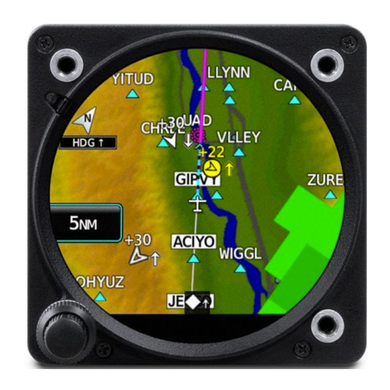
Page 131: Navigation Data Displayed On Map
Direct-to leg displayed on the 'Map' Page Active Leg Waypoint Other flight plan legs shown in white Active flight plan leg shown in magenta Flight plan displayed on the 'Map' Page (Flight plan information received from external source) 190-02246-01 Rev. A Garmin GI 275 Pilot's Guide... - Page 132 All procedures must be loaded and activated using the external navigator. For information on changing the navigation source of the CDI, and for information on the display of vertical deviation, see the Flight Instruments Section. Garmin GI 275 Pilot's Guide 190-02246-01 Rev. A...
-
Page 133: Mfd Data
'MFD Data' Page (Flight Plan Information Received from External Source) Changing the information shown in the MFD Data Fields: 1) From the 'MFD Data' Page, open the menu. 2) Select the MFD Data Options Button. 3) Select the desired Field Button. 190-02246-01 Rev. A Garmin GI 275 Pilot's Guide... -
Page 134: Flight Plan Sharing
Garmin Pilot to an external navigator. For example, when a mobile device is paired to the MFI, the pilot may create a flight plan in Garmin Pilot and Connext will share the flight plan to another configured, compatible navigator onboard. - Page 135 Direct-to navigation is discussed previously in this section. TAWS/terrain and SVT features are not available with the internal VFR GPS. Navigation using VFR VFR GPS System Message System Message Description Reversion to VFR GPS - System Message 190-02246-01 Rev. A Garmin GI 275 Pilot's Guide...
- Page 136 TAWS/terrain and SVT features will be lost, and the CDI will be removed. Complete Loss of GPS - 'No GPS POS' annunciation on 'HSI Map' Page Garmin GI 275 Pilot's Guide 190-02246-01 Rev. A...
-
Page 137: Section 5 Hazard Avoidance
Datalink weather services, including SiriusXM Weather and Flight Information Services- Broadcast (FIS-B) may be transmitted from a ground station or satellite and received for display on the MFI. 190-02246-01 Rev. A Garmin GI 275 Pilot's Guide... - Page 138 Weather products provided by the subscription should be listed in green indicating they are available for use. Items listed in gray indicate data is unavailable. Garmin GI 275 Pilot's Guide 190-02246-01 Rev. A...
- Page 139 FIS-B is a component of the Automatic Dependent Surveillance Broadcast (ADS-B) system, which offers both weather and traffic data; refer to the ADS-B Traffic discussion later in this section for a more detailed discussion of the ADS-B system and its capabilities. 190-02246-01 Rev. A Garmin GI 275 Pilot's Guide...
-
Page 140: Datalink Weather Products
Weather Product Symbol METARs (N/A) TAFs SIGMETs AIRMETs Pilot Weather Report (PIREP) Winds Aloft Temporary Flight Restriction (TFR) Radar Precipitation (US) (NEXRAD) (Regional) *Lightning *Cloud Top *Echo Top *Cell Movement Garmin GI 275 Pilot's Guide 190-02246-01 Rev. A... - Page 141 They can also contain information on precipitation amounts, lightning, and other critical data. If METAR data is available for an airport, a color- coded flag is shown next to the airport. 190-02246-01 Rev. A Garmin GI 275 Pilot's Guide...
- Page 142 Low IFR: Ceiling below 500 ft. AGL and/or visibility less than one mile. Unknown Selected METAR flag Range Touch to display METAR text Touch to display Time Stamp information Selected METAR on 'SXM WX' Page Garmin GI 275 Pilot's Guide 190-02246-01 Rev. A...
- Page 143 A SIGMET is widespread and must affect or be forecast to affect an area of at least 3,000 square miles. SIGMETs are displayed as a yellow-dashed line. SIGMET 190-02246-01 Rev. A Garmin GI 275 Pilot's Guide...
- Page 144 The wind barbs always point in the direction the wind is coming from. The wind speed is depicted using flags at the end of the wind barb. A short wind flag is 5 knots, a long wind flag is 10 knots, and a triangle flag is 50 knots. Garmin GI 275 Pilot's Guide 190-02246-01 Rev. A...
- Page 145 Hazard Avoidance Wind Barb Range Displayed Weather Altitude Setting Winds Aloft displayed on the 'SXM WX' Page Wind Barb Symbols 190-02246-01 Rev. A Garmin GI 275 Pilot's Guide...
- Page 146 TFRs are represented as an area outlined in amber. Selected TFR Range Touch to display TFR Info Touch to display Time Stamp information TFR on weather page Garmin GI 275 Pilot's Guide 190-02246-01 Rev. A...
- Page 147 » NEXRAD base reflectivity is sampled at the minimum antenna elevation angle. An individual NEXRAD site cannot depict high altitude storms at close ranges and has no information about storms directly over the site. » Radar coverage only extends to 55°N. 190-02246-01 Rev. A Garmin GI 275 Pilot's Guide...
- Page 148 Source selection for SiriusXM radar imagery includes the following: ƒ Composite – Displays composite reflectivity image scanned from multiple elevation angles ƒ Base – Displays base reflectivity image scanned from a single elevation angle Garmin GI 275 Pilot's Guide 190-02246-01 Rev. A...
- Page 149 The exact location of the lightning strike is not displayed. Range Lightning Data Touch to display Time Stamp information Lightning on 'SXM WX' Page 190-02246-01 Rev. A Garmin GI 275 Pilot's Guide...
- Page 150 Cells are represented by orange squares, with direction of movement indicated with short, orange arrows. Critical information about the storm cell (tops and intensity) can be viewed by touching the storm cell. Garmin GI 275 Pilot's Guide 190-02246-01 Rev. A...
- Page 151 New data appears when it becomes available. Freezing Level Altitude Color coded contour line for each freezing level Freezing Levels on 'SXM WX' Page 190-02246-01 Rev. A Garmin GI 275 Pilot's Guide...
- Page 152 The County Warnings weather product provides specific public awareness and protection weather warnings from the National Weather Service (NWS). This can include information on tornadoes, severe thunderstorms, and flood conditions. County Warnings Symbols Garmin GI 275 Pilot's Guide 190-02246-01 Rev. A...
- Page 153 Surface Analysis and City Forecast (SiriusXM) Surface Analysis and City Forecast information is available for current and forecast weather conditions. Forecasts are available for intervals of 12, 24, 36, and 48 hours. Surface Analysis Symbols 190-02246-01 Rev. A Garmin GI 275 Pilot's Guide...
- Page 154 Turbulence is classified as light, moderate, severe, or extreme, at altitudes between 21,000 ft and 45,000 ft. Turbulence information is intended to supplement AIRMETs, SIGMETs, and PIREPs. Turbulence Legend Garmin GI 275 Pilot's Guide 190-02246-01 Rev. A...
-
Page 155: Weather Product Age
60 minutes SIGMETs/AIRMETs 60 minutes Pilot Weather Report (PIREP) 90 minutes Winds Aloft 90 minutes Temporary Flight Restriction (TFR) 60 minutes Radar Precipitation (NEXRAD) 30 minutes Lightning 30 minutes *Cloud Top 60 minutes 190-02246-01 Rev. A Garmin GI 275 Pilot's Guide... - Page 156 The color of each weather product listed on the 'Time Stamps' Screen will change depending on the status of each weather product, as shown in the figure below. Garmin GI 275 Pilot's Guide 190-02246-01 Rev. A...
-
Page 157: Display Of Weather Products
If more information is available, such as a textual report for the weather product, that information can be displayed by touching the weather product on the weather page, and then selecting the Info Button. 190-02246-01 Rev. A Garmin GI 275 Pilot's Guide... - Page 158 3) Select the Info Button. The 'WX Data' Screen is displayed showing the information available for the selected weather product. AIRMET Product Info on 'WX Data' Screen Garmin GI 275 Pilot's Guide 190-02246-01 Rev. A...
- Page 159 Select the City Forecast Button to display the 'Forecast' Screen. A list of available city forecasts is displayed. 3) Select the desired Forecast Button, or select the Off Button to disable the display of the forecast. 190-02246-01 Rev. A Garmin GI 275 Pilot's Guide...
-
Page 160: Stormscope Lightning Detection System
To change the range, select the Range Button, and then turn the Inner Knob clockwise to zoom in and decrease the range, or counterclockwise to zoom out and increase the range. Garmin GI 275 Pilot's Guide 190-02246-01 Rev. A... - Page 161 This is to ensure the strike and/or cell positions are depicted accurately in relation to the nose of the aircraft. Manually clearing Stormscope cell or strike information: From the 'Lightning' Page, select the Clear Strikes Button. 190-02246-01 Rev. A Garmin GI 275 Pilot's Guide...
-
Page 162: Terrain
See the pertinent flight manual for the external TAWS equipment Terrain Configurations The following is required for proper terrain display operation: • Valid 3-D GPS position • Valid terrain and obstacle databases Garmin GI 275 Pilot's Guide 190-02246-01 Rev. A... - Page 163 100 feet and 1000 feet below the aircraft altitude is depicted in yellow. The color black indicates terrain is more than 1000 feet below the aircraft altitude. For additional safety, wire obstacle data is provided by Garmin’ s WireAware ™...
- Page 164 Red wire obstacle is above or within 100 ft below the aircraft altitude Yellow wire obstacle is between 100 ft and 1000 ft below the aircraft altitude White wire obstacle is more than 1000 ft below aircraft altitude Relative Wire Obstacles and Colors Garmin GI 275 Pilot's Guide 190-02246-01 Rev. A...
-
Page 165: Displaying Terrain Data
Terrain data may be displayed in 360° View or Arc View. The 'Terrain' Page has seven range settings available between 1 and 100 NM. The current range is indicated on the Range Button. Range may be changed by zooming in and out using the Inner Knob. 190-02246-01 Rev. A Garmin GI 275 Pilot's Guide... - Page 166 Map Panning discussion of the Navigation Section for instructions on panning the map. Item Displayed Description GSL Altitude Displays current GPS height above mean sea level on the 'Terrain' Page. Legend Displays legend of color designations for terrain and obstacle relative altitude ranges. Garmin GI 275 Pilot's Guide 190-02246-01 Rev. A...
-
Page 167: Terrain Alerts
The system automatically disables FLTA alerts when the aircraft is less than 200 feet above the destination runway elevation while within 0.5 nm of the approach runway or the aircraft is between runway ends. 190-02246-01 Rev. A Garmin GI 275 Pilot's Guide... - Page 168 NOTE: Only visual annunciations will be provided if the Terrain Function is using an external TAWS-B system. For information on TAWS-B aural alerts, see the pertinent flight manual for that system. Garmin GI 275 Pilot's Guide 190-02246-01 Rev. A...
- Page 169 » Touch the Close Button (returns to the currently viewed page), or » Touch the Inhibit Button (inhibits alerts and returns to the currently viewed page), or » Touch the Go to Terrain Button (accesses the 'Terrain' Page). 190-02246-01 Rev. A Garmin GI 275 Pilot's Guide...
- Page 170 NOTE: Only visual annunciations will be provided if the Terrain Function is using an external TAWS-B system. For information on TAWS-B voice alerts, see the pertinent flight manual for that system. Garmin GI 275 Pilot's Guide 190-02246-01 Rev. A...
-
Page 171: Terrain Inhibit
1) From the 'Terrain' Page, open the page menu and select Terrain Options. 2) Select the Terrain Inhibit Button to inhibit/enable terrain alerts. The annunciator bar is green when terrain alerts are inhibited. 190-02246-01 Rev. A Garmin GI 275 Pilot's Guide... -
Page 172: Terrain Status
* “Terrain System Available” will be heard when sufficient GPS signal is received, or Terrain database coverage area re-entered. ** Aural alert provided by the external TAWS-B System Terrain System Status Annunciations Garmin GI 275 Pilot's Guide 190-02246-01 Rev. A... -
Page 173: Synthetic Vision Terrain
Traffic Advisory System (TAS) Traffic Alert and Collision Avoidance System (TCAS) - Traffic information, interrogated from transponder-equipped aircraft, is sent to TCAS the compatible equipment system - Higher range allowed with TCAS Traffic Source Descriptions 190-02246-01 Rev. A Garmin GI 275 Pilot's Guide... -
Page 174: Display Of Traffic Information
- Traffic Information Banner - Altitude Filter setting - ADS-B Status (If configured) - Traffic Source mode - Traffic motion information TCAS - Orientation - Range setting - Target Selection Button 'Traffic' Page Information Garmin GI 275 Pilot's Guide 190-02246-01 Rev. A... - Page 175 1) Primary HSI Configuration: From the 'HSI Map' Page, open the menu and select Traffic Opts > Altitude Filter. Standby ADI or MFD Configurations: From the 'Traffic' Page, open the menu and select Traffic Options > Altitude Filter. 2) Select the desired Altitude Setting Button. 190-02246-01 Rev. A Garmin GI 275 Pilot's Guide...
- Page 176 Advisories Selected target on 'Traffic' Page with TCAS Viewing traffic target information: Touch the desired target symbol on the 'Traffic' Page. Information about the selected target is displayed in the information banner. Garmin GI 275 Pilot's Guide 190-02246-01 Rev. A...
- Page 177 This annunciation will flash for five seconds before being displayed steady until the threat is cleared. TFC Annunciation on TFC Annunciation on Primary ADI Primary HSI Primary ADI and Primary HSI Traffic Alert Examples 190-02246-01 Rev. A Garmin GI 275 Pilot's Guide...
- Page 178 A Traffic Advisory is displayed within the selected range. TRAFFIC System cannot determine bearing of Traffic Advisory. Annunciation indicates distance in nm, altitude separation in hundreds TA X.X ± XX of feet, and altitude trend arrow (climbing/descending). Garmin GI 275 Pilot's Guide 190-02246-01 Rev. A...
- Page 179 FAILED Traffic service is unavailable or out of range UNAVAIL Traffic function is in Standby Mode STBY STANDBY * Contact a service center or Garmin dealer for corrective action. Traffic Failure Annunciations 190-02246-01 Rev. A Garmin GI 275 Pilot's Guide...
-
Page 180: Traffic Data By Source
TA which is detected, but is outside the range of the map, is indicated on the outer ring of the traffic map by a half TA symbol at the relative bearing of the intruder. Garmin GI 275 Pilot's Guide 190-02246-01 Rev. A... - Page 181 TIS enters Standby Mode (on the ground) or Operating Mode (in the air). If TIS fails the test after power is applied to the system, an annunciation is shown in the center of the 'Traffic' Page. 190-02246-01 Rev. A Garmin GI 275 Pilot's Guide...
- Page 182 These broadcasts contain information such as GPS position, identity (Flight ID, Call Sign, Tail Number, ICAO registration number, etc.), ground track, ground speed, pressure altitude, and emergency status. Garmin GI 275 Pilot's Guide 190-02246-01 Rev. A...
- Page 183 MHz and the other is transmitting on 978 MHz, the ground station retransmits the data from each aircraft on the other link to ensure the two aircraft can “see” each other as traffic. 190-02246-01 Rev. A Garmin GI 275 Pilot's Guide...
- Page 184 Traffic Advisory out of the selected display range without directional information. Displayed at outer range ring at proper bearing. Proximity Advisory with directional information. Points in the direction of the aircraft track. Garmin GI 275 Pilot's Guide 190-02246-01 Rev. A...
- Page 185 1) Primary HSI Configuration: From the 'HSI Map' Page, open the menu and select Traffic Opts. Standby ADI or MFD Configurations: From the 'Traffic' Page, open the menu and select Traffic Options. 2) Select the Traffic Grouping Button to enable or disable the function. 190-02246-01 Rev. A Garmin GI 275 Pilot's Guide...
- Page 186 "ADS: On" status means that both AIRB and ATAS applications are active. A test of the traffic system may be initiated, which will display a test pattern on the 'Traffic' Page. Then, the system returns to normal operation once the test is complete. Garmin GI 275 Pilot's Guide 190-02246-01 Rev. A...
- Page 187 ƒ Closure Rate ƒ Track ƒ Ground Speed Information Banner Traffic Advisory 2200' above climbing Altitude Filter ADS-B Application Traffic Type and Range Status Traffic Advisories Motion Vector Duration Setting 'Traffic' Page with ADS-B 190-02246-01 Rev. A Garmin GI 275 Pilot's Guide...
- Page 188 Surveillance range is dependent upon the configured traffic system. In areas of greater transponder traffic density or when TCAS systems are detected, the on-board traffic system automatically reduces its interrogation transmitter power (and therefore range) in order to limit potential interference from other signals. Garmin GI 275 Pilot's Guide 190-02246-01 Rev. A...
- Page 189 The traffic system automatically suppresses the display of altitude-reporting aircraft on the ground under either of the following conditions: » On-ground aircraft is equipped with a Mode S transponder » On-ground aircraft is equipped with a Mode C transponder 190-02246-01 Rev. A Garmin GI 275 Pilot's Guide...
- Page 190 A 'TRAFFIC' annunciation will appear on the 'Traffic' Page, or as a pop-up alert when a TA is issued. A TA will be displayed for at least eight seconds, even if the condition(s) that initially triggered the TA are no longer present. Garmin GI 275 Pilot's Guide 190-02246-01 Rev. A...
- Page 191 1) From the 'Traffic' Page, open the page menu and select Traffic Options. 2) Select the Test Button. A system test is initiated and 'TEST' is displayed next to the Traffic Source on the 'Traffic' Page. 190-02246-01 Rev. A Garmin GI 275 Pilot's Guide...
- Page 192 Hazard Avoidance Blank Page Garmin GI 275 Pilot's Guide 190-02246-01 Rev. A...
-
Page 193: Section 6 Autopilot
Flight Director / AFCS Controller, if configured. The GI 275 Multi-Function Instrument (MFI) receives and analyzes inputs from an external Flight Director, which in turn provides pitch, roll, and yaw gyro outputs to an Autopilot. The Autopilot operates the flight control servos which provides automatic flight control. -
Page 194: Flight Control
The Command Bars move vertically to indicate pitch commands and bank left or right to indicate roll commands. Command Bars Aircraft Symbol Single-Cue Command Bars When the Autopilot is engaged, the magenta Command Bars and the amber Aircraft Symbol move together in unison. Garmin GI 275 Pilot's Guide 190-02246-01 Rev. A... -
Page 195: Engaging The Autopilot
Autopilot Engaged DISENGAGING THE AUTOPILOT Manual Disengagement The Autopilot is manually disengaged from the external Flight Director / AFCS Controller by using the A/P DISC Switch. When disengaged, the Command Bars are removed. 190-02246-01 Rev. A Garmin GI 275 Pilot's Guide... - Page 196 NOTE: In the event of an in-flight restart, the Autopilot may disengage. Discrete Configurations The MFI can be configured to have airspeed discrete inputs tied to Autopilot. Activation of a discrete may be configured to automatically disengage the Autopilot given your external hardware. Garmin GI 275 Pilot's Guide 190-02246-01 Rev. A...
-
Page 197: Section 7 Additional Features
The Flight Data Logging feature automatically connects and stores critical flight and engine data to Garmin Pilot through Connext or to a USB device through Garmin's proprietary GSB 15. Approximately 1,000 flight hours can be recorded for each 1GB of available space. - Page 198 Spot (e.g., 'RUNWAY/TAXIWAY INTERSECTION,' 'COMPLEX INTERSECTION,' etc.). The Hot Spot Info Button also appears at the bottom of the MFI. 2) Touch the Hot Spot Info Button to reveal the 'Hot Spot Info' Page. Hot Spot Info Garmin GI 275 Pilot's Guide 190-02246-01 Rev. A...
-
Page 199: Radar Altimeter (Optional)
The Rad Alt is not forward looking and the AGL reading is not a good indication of future AGL altitudes. The MFI uses Garmin or compatible hardware to measure height AGL by timing how long it takes a radio beam to reflect off the ground and return to the aircraft. - Page 200 When the aircraft is airborne and descends through the set DH, an amber 'DH' annunciation illuminates, the digital AGL altitude becomes amber, the DH bug becomes amber, and the aural alert, "Minimums, Minimums" sounds. Garmin GI 275 Pilot's Guide 190-02246-01 Rev. A...
-
Page 201: Radar Altimeter Test
(e.g., 50'). If the test fails, the Rad Alt will display 0' throughout the test where 50' is expected to be displayed otherwise. Testing the Radar Altimeter: 1) From the 'Rad Alt' Page Menu, select Rad Alt Options. 2) Select Test to initiate the Rad Alt Test. 190-02246-01 Rev. A Garmin GI 275 Pilot's Guide... -
Page 202: Flight Data Logging
The Flight Data Logging feature automatically connects and stores critical flight and engine data to Garmin Pilot through Connext or to a USB device through Garmin's proprietary GSB 15. Data is recorded once each second while the power is applied to the system. - Page 203 All flight data logged on a specific date is stored in a file named in a format which includes the date, time, and nearest airport identifier. The file is created automatically each time power is applied to the MFI, provided a USB device has been inserted. 190-02246-01 Rev. A Garmin GI 275 Pilot's Guide...
-
Page 204: Data Parameters
– Normal Acceleration (g) – CDT (deg. F) – Pitch/Roll (deg.) – GPS Fix (e.g., 2D, 3D, 3DDiff) – Primary EGT (deg. F) – Indicated Airspeed (kts) – Horizontal Alert Limit (m) Garmin GI 275 Pilot's Guide 190-02246-01 Rev. A... -
Page 205: D2 ™ Pilot Watch Connectivity (Optional)
3) Scroll down and select Pair a Device. On the 'Pair Device' Screen, the MFI will display its Bluetooth name and prompt the pilot to "Please remain on this page while pairing your Bluetooth device." 190-02246-01 Rev. A Garmin GI 275 Pilot's Guide... - Page 206 NOTE: It is not uncommon for the status of a BLE device, such as the D2 Watch, to ™ annunciate 'Status Offline' and still function properly. This is a feature of BLE reduced power consumption and alternating status is expected. Garmin GI 275 Pilot's Guide 190-02246-01 Rev. A...
-
Page 207: Synthetic Vision Technology (Svt ™ ) (Optional)
™ WARNING: Use appropriate primary systems for navigation, and for terrain, obstacle, and traffic avoidance. Garmin SVT™ is intended as an aid to situational awareness only and may not provide either the accuracy or reliability upon which to solely base decisions and/or plan maneuvers to avoid terrain, obstacles, or traffic. - Page 208 Navigation must not be predicated solely upon the use of the synthetic terrain or obstacle data displayed by SVT. Pitch Scale Flight Path Artificial Marker (FPM) Artificial Terrain Zero-Pitch Line Typical SVT Display Garmin GI 275 Pilot's Guide 190-02246-01 Rev. A...
-
Page 209: Svt Features
Activating and deactivating Horizon Headings: 1) From the 'ADI' Page, open the menu and select ADI Options > Terrain SVT > Settings. 2) Select the Horizon Headings Button to toggle horizon heading depiction. 190-02246-01 Rev. A Garmin GI 275 Pilot's Guide... - Page 210 Activating and deactivating Airport Signs: 1) From the 'ADI' Page, open the menu and select ADI Options > Terrain SVT. 2) Select the Settings Button. 3) Select the Airport Signs Button to toggle airport sign depiction. Garmin GI 275 Pilot's Guide 190-02246-01 Rev. A...
- Page 211 Runway number SVT Airport Runway WARNING: Do not use the Garmin SVT runway depiction as the sole means for determining the proximity of the aircraft to the runway or for maintaining the proper approach path angle during landing. NOTE: Not all airports have runways with endpoint data in the database; therefore, SVT does not display these runways.
- Page 212 FLTA alert. Obstacles greater than 1,000 feet below the aircraft altitude are not shown. Obstacles are shown behind the airspeed and altitude displays. Garmin GI 275 Pilot's Guide 190-02246-01 Rev. A...
-
Page 213: Svt Troubleshooting
SVT becomes disabled without the following data resources: – Attitude data – 9.9 arc-second terrain data – Heading data – Obstacle data – External GPS position data – TAWS/Terrain-FLTA not available in test mode, or if failed 190-02246-01 Rev. A Garmin GI 275 Pilot's Guide... - Page 214 Additional Features Blank Page Garmin GI 275 Pilot's Guide 190-02246-01 Rev. A...
-
Page 215: Section 8 Appendices
A caution alert is annunciated in amber text and may be accompanied by an aural alert. Advisory: • This level of alert provides general information to the pilot. A message advisory alert is annunciated in white text. 190-02246-01 Rev. A Garmin GI 275 Pilot's Guide... - Page 216 Appendix A Traffic Pop-up Alert TRAFFIC Annunciation Caution Alert Level Example Pop-Up Alert Red or Amber 'X' Annunciation Indicates System Component Failure Example of Failure Annunciations Garmin GI 275 Pilot's Guide 190-02246-01 Rev. A...
-
Page 217: System Messages
The following alphabetized table lists the various System Messages. CAUTION: Do not allow repairs to be made by anyone other than an authorized Garmin service center. Unauthorized repairs or modifications could void both the warranty and affect the airworthiness of the aircraft. - Page 218 Low bus voltage Pilot defined engine advisory limitation exceeded Low EST fuel remaining Pilot defined engine advisory limitation exceeded Estimated fuel on board or endurance is below the pilot defined Low Endurance limit Garmin GI 275 Pilot's Guide 190-02246-01 Rev. A...
- Page 219 While on the ground, the configuration CRC of an AHRS or ADC LRU does not match the unit's stored configuration CRC While on the ground, Garmin Engine Sensor (e.g., GEA 110, GEA 71B, etc.) Configuration CRC doesn't match unit's saved CRC 190-02246-01 Rev.
- Page 220 Traffic function inoperative TIS-A device reports traffic fail Communication with TIS-A device is lost Traffic system in standby TIS-A device reports standby mode for more than 60 seconds while in air Garmin GI 275 Pilot's Guide 190-02246-01 Rev. A...
- Page 221 FIS-B data USB and WiFi Unavailable While on internal battery operation, the unit conserves energy by disabling these functions. VFR GPS is being used VFR GPS is being used System Messages 190-02246-01 Rev. A Garmin GI 275 Pilot's Guide...
- Page 222 Appendix A Blank Page Garmin GI 275 Pilot's Guide 190-02246-01 Rev. A...
-
Page 223: Appendix B: Database Information
NOTE: If the pilot/operator wants or needs to adjust the database, contact Garmin Product Support. NOTE: The FAA has asked Garmin to remind pilots who fly with Garmin database- dependent avionics of the following: • It is the pilot’s responsibility to remain familiar with all FAA regulatory and advisory guidance and information related to the use of databases in the National Airspace System. -
Page 224: Available Databases
The internal navigation database provides location and facility information for thousands of airports, VORs, NDBs, and more. Updates to the navigation database are available every 28 days online (flygarmin.com). There are two navigation database products available: the Garmin Navigation Database or the Jeppesen Navigation Database, which is sourced by Jeppesen. -
Page 225: Database Troubleshooting Tips
- Ensure the Database Concierge is enabled on the mobile device and on the MFI - Restart the MFI while pressing the Inner Knob until the Garmin logo is fully illuminated to view all database updates on the database card, regardless of effectivity... - Page 226 Appendix B Blank Page Garmin GI 275 Pilot's Guide 190-02246-01 Rev. A...
-
Page 227: Appendix C: Aviation Terms And Acronyms
Aircraft Owners and Pilots System Association Airplane Flight Manual Autopilot ATS Facilities Notification AP DISC Autopilot Disconnect AFMS Airplane Flight Manual APPR, APR Approach Supplement Airport, Aerodrome AFRM Airframe APTSIGNS Airport Signs Above Ground Level 190-02246-01 Rev. A Garmin GI 275 Pilot's Guide... - Page 228 Cylinder Head Temperature B ALT Barometric Altitude CHKLIST Checklist BARO Barometer, Barometric Course to Intercept Leg BATT Battery Cloud Backcourse Clear Bearing The compass direction from Centimeter the present position to a destination waypoint. Garmin GI 275 Pilot's Guide 190-02246-01 Rev. A...
- Page 229 Deviation see also Course, Course to Direct to Fix Leg Steer DFLT Default CRSR Cursor Directional Gyro Conflict Situational DGRD Degrade Awareness Decision Height Current Speed Control 190-02246-01 Rev. A Garmin GI 275 Pilot's Guide...
- Page 230 Desired Track right of the desired course on an active flight plan or Data Quality Requirements direct-to. Enter Empty, East see also Estimated Position Engine and Airframe Error Systems Garmin GI 275 Pilot's Guide 190-02246-01 Rev. A...
- Page 231 Degrees Fahrenheit See also Fuel Over Course From Fix to Altitude Destination Flight Path Angle Federal Aviation Administration Flight Plan FADEC Full Authority Digital Engine Feet Per Minute, Flight Path Control Marker 190-02246-01 Rev. A Garmin GI 275 Pilot's Guide...
- Page 232 Garmin Satellite Data Link Ground Track See Track Garmin Data Radio Garmin Reference System Garmin Display Unit Ground Speed, Glideslope Garmin Engine/Airframe Garmin Servo Adapter Unit Garmin Data Concentrator Generator Geodetic Sea Level Garmin GI 275 Pilot's Guide 190-02246-01 Rev. A...
- Page 233 Instrument Landing System of Merit uncertainty in the aircraft’s Instrument Meteorological horizontal position. Conditions Hover Inch HOV-P Hover Prediction INACTV Inactive Hectopascal INC FUEL Increase Fuel Hover Power Indicator Indicator, Indicated Horizontal Protection Level 190-02246-01 Rev. A Garmin GI 275 Pilot's Guide...
- Page 234 Line Replaceable Unit Label LSB V Lower Sideband Voice Pound Left Liquid Crystal Display LTNG Lightning Local Level Landing Distance Available ETA at Final Destination Meter, Middle Marker, Mach Light Emitting Diode Maximum Speed Garmin GI 275 Pilot's Guide 190-02246-01 Rev. A...
- Page 235 ATC Minimum clearance) Minimum Safe Uses Grid MORAs to NOTAM Notice To Airman Altitude (MSA) determine a safe altitude Power Turbine Speed within ten miles of the aircraft present position. Rotor Speed 190-02246-01 Rev. A Garmin GI 275 Pilot's Guide...
- Page 236 Reference Supplement Remaining (fuel remaining), POS, POSN Position Reminder Pounds per Hour Required Parts per Million Reserve (fuel reserve entered by pilot) P. POS Present Position Reverse, Revision, Revise PRES, PRESS Pressure Garmin GI 275 Pilot's Guide 190-02246-01 Rev. A...
- Page 237 STAB Stabilization Static Air Temperature STAL Stall SBAS Satellite-Based STAR Standard Terminal Arrival Augmentation System Route SCIT Storm Cell Identification STATS Statistics and Tracking STBY Standby Secure Digital Standard Second(s) STRMSCP Stormscope 190-02246-01 Rev. A Garmin GI 275 Pilot's Guide...
- Page 238 Procedure Turn TERM Terminal TWIP Terminal Weather Track Between Two Fixes Information for Pilots Transmit Temporary Flight Restriction Target Universal Access Transceiver T HDG True Heading Ultra-High Frequency Traffic Information Service UNAVAIL Unavailable Garmin GI 275 Pilot's Guide 190-02246-01 Rev. A...
- Page 239 Heading Vector to Intercept Maximum Speedbrake Speed VLOC VOR/Localizer Receiver Stall Speed Heading Vector to Manual Termination Leg Takeoff Flap Retraction Speed Visual Meteorological Conditions Maximum Tire Speed TIRE VNAV, VNV Vertical Navigation 190-02246-01 Rev. A Garmin GI 275 Pilot's Guide...
- Page 240 WATCH Weather Attenuated Color Highlight WGS-84 World Geodetic System - 1984 WI-FI, WIFI Wireless Local Area Network based on IEEE 802.11 Weight on Gear Weight on Wheels Waypoint(s) Weight World Wide Weather Garmin GI 275 Pilot's Guide 190-02246-01 Rev. A...
-
Page 241: Appendix D: Display Symbols
Appendix D APPENDIX D: DISPLAY SYMBOLS VFR SYMBOLS Item Symbol Unknown Non-towered, Non-serviced Towered, Non-serviced Non-towered, Serviced Towered, Serviced Soft Surface, Non-serviced Soft Surface, Serviced Soft Surface, Private Paved, Private Heliport Airports 190-02246-01 Rev. A Garmin GI 275 Pilot's Guide... -
Page 242: Ifr Symbols
LOM (Compass Locator at Outer State Highway Marker) NDB (Non-Directional Radio National Highway Beacon) Small City VOR/DME Medium City ILS/DME or DME Only Large City VORTAC Miscellaneous TACAN Navaids Item Symbol Low-Altitude High-Altitude Airways Garmin GI 275 Pilot's Guide 190-02246-01 Rev. A... -
Page 243: Airspace Symbols
Class B, Class E, CTA Class A, Class C, TMA Class D Mode C Veil TRSA Danger, Alert, or Training Area Restricted, Prohibited, or Warning Area Radar Area ATZ, TIZ MATZ ADIZ Misc./Unknown Airspace 190-02246-01 Rev. A Garmin GI 275 Pilot's Guide... - Page 244 Appendix D Blank Page Garmin GI 275 Pilot's Guide 190-02246-01 Rev. A...
-
Page 245: Index
Engine Indication System (EIS) 55 Bluetooth 21 Abnormal Operations 69 Advisory Options 61 Alerting Gauges 60 Caution 193 Alerts 69 Caution, EIS 69 Annunciations 69 CDI Scale 44 CHT Page 66 CDI Source 40, 44 190-02246-01 Rev. A Garmin GI 275 Pilot's Guide... - Page 246 Fuel Flow Calibration 67, 68 Message Alert Indicator 10 Fuel Remaining 56, 67 METARs 99, 119 MFD Data 111 Garmin Pilot 21, 29, 30, 107 Minimum Altitude Alerting 49, 50 Geodetic Sea Level (GSL) 141, 143, 144 Miscompare 13, 50 Glidepath 42...
- Page 247 Satellite Information 15 Inhibit 147 SIGMET 121 Legend 143, 144 SiriusXM Weather Obstacles 142 Activation 116 Test 150 Cell Movement 128 View 143 Cloud Tops 128 Wire Obstacles 142 County Warnings 130 190-02246-01 Rev. A Garmin GI 275 Pilot's Guide...
- Page 248 Primary HSI 3 Standby ADI 3 Standby HSI 3 Units of Measure 19 Unit Types 2 Basic 2 With Internal ADAHRS 3 With Internal ADAHRS/Autopilot 3 Unusual Attitudes 53 Updating Databases 27, 28 Garmin GI 275 Pilot's Guide 190-02246-01 Rev. A...
- Page 250 Liberty House, Hounsdown Business Park Southampton, Hampshire SO40 9LR U.K. Garmin Corporation No. 68, Zhangshu 2nd Road Xizhi District, New Taipei City, Taiwan Contact Garmin Product Support or view warranty information at flygarmin.com. 190-02246-01 Rev. A © 2019 Garmin Ltd. or its subsidiaries...