Endress+Hauser Micropilot FMR20 Operating Instructions Manual
Modbus rs485 free space radar
Hide thumbs
Also See for Micropilot FMR20:
- Operating instructions manual (102 pages) ,
- Technical information (60 pages) ,
- Brief operating instructions (40 pages)

Related Manuals for Endress+Hauser Micropilot FMR20


Summary of Contents for Endress+Hauser Micropilot FMR20
- Page 1 Products Solutions Services BA01931F/00/EN/03.20 71473149 2020-03-30 01.00.zz (Device firmware) Operating Instructions Micropilot FMR20 MODBUS RS485 Free space radar...
- Page 2 Micropilot FMR20 MODBUS RS485 Order code: XXXXX-XXXXXX Ser. no.: XXXXXXXXXXXX Ext. ord. cd.: XXX.XXXX.XX Serial number www.endress.com/deviceviewer Endress+Hauser Operations App A0023555 Endress+Hauser...
-
Page 3: Table Of Contents
Micropilot FMR20 MODBUS RS485 Table of contents Table of contents About this document ....5 Electrical connection ....21 Document function . - Page 4 Table of contents Micropilot FMR20 MODBUS RS485 9.6.5 Bluetooth® wireless technology ..36 15.1.2 Section: Measured values ..68 15.1.3 Section: Device status ... .
-
Page 5: About This Document
Micropilot FMR20 MODBUS RS485 About this document About this document Document function These Operating Instructions provide all of the information that is required in various phases of the life cycle of the device including: • Product identification • Incoming acceptance •... -
Page 6: Documentation
For an overview of the scope of the associated Technical Documentation, refer to the following: • W@M Device Viewer (www.endress.com/deviceviewer): Enter the serial number from nameplate • Endress+Hauser Operations App: Enter the serial number from the nameplate or scan the 2D matrix code (QR code) on the nameplate 1.3.1 Technical Information (TI) -
Page 7: Terms And Abbreviations
Android, Google Play and the Google Play logo are trademarks of Google Inc. Bluetooth® The Bluetooth® word mark and logos are registered trademarks owned by the Bluetooth SIG, Inc. and any use of such marks by Endress+Hauser is under license. Other trademarks and trade names are those of their respective owners. Endress+Hauser... -
Page 8: Basic Safety Instructions
‣ With regard to special media and media used for cleaning, please contact the manufacturer. Endress+Hauser will be happy to assist in clarifying the corrosion- resistant properties of wetted materials but does not accept any warranty or liability. Residual risks... -
Page 9: Workplace Safety
The measuring system meets the legal requirements of the applicable EU Directives. These are listed in the corresponding EU Declaration of Conformity along with the standards applied. Endress+Hauser confirms successful testing of the device by affixing to it the CE mark. Endress+Hauser... -
Page 10: Product Description
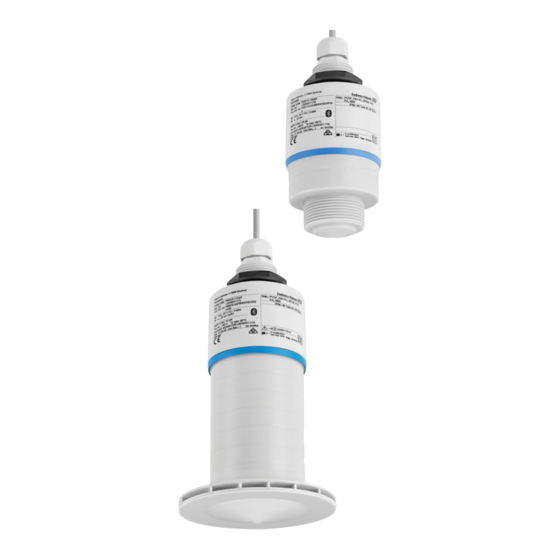
Product description Micropilot FMR20 MODBUS RS485 Product description Product design A0028416 1 Device design Device with 40 mm antenna Device with 80 mm antenna Sensor housing Seal Process connection rear side Cable gland Pipe adapter O-ring Counter nut Design ring... -
Page 11: Incoming Acceptance And Product
‣ Enter the serial number from the nameplate into the Endress+Hauser Operations App or use the Endress+Hauser Operations App to scan the 2-D matrix code (QR Code) provided on the nameplate All the information about the measuring device and the scope of the associated Technical Documentation are displayed. -
Page 12: Nameplate
Incoming acceptance and product identification Micropilot FMR20 MODBUS RS485 Nameplate Order code: Ser. no.: Ext. ord. cd.: MWP: Tp max: DeviceID: Dev.Rev.: ex works Mat.: if modification see sep. label Date: A0029096 2 Nameplate of Micropilot Manufacturer address Device name Order code Serial number (ser. -
Page 13: Installation
Micropilot FMR20 MODBUS RS485 Installation Installation Installation conditions 5.1.1 Installation types A0030605 3 Wall, ceiling or nozzle installation Wall or ceiling mount, adjustable Mounted at front thread Mounted at rear thread Ceiling installation with counter nut (included in delivery) -
Page 14: Position For Installation On A Vessel
Installation Micropilot FMR20 MODBUS RS485 A0028413 4 Nozzle installation 80 mm (3 in) antenna 40 mm (1.5 in) antenna The maximum length of the nozzle L depends on the nozzle diameter D. Please note the limits for the diameter and length of the nozzle. -
Page 15: Device Alignment For Installation On A Vessel
Micropilot FMR20 MODBUS RS485 Installation • If possible install the sensor so that its lower edge projects into the vessel. • Recommended distance A wall - nozzle outer edge: ~ ¹⁄₆ of the vessel diameter D. Under no circumstances should the device be mounted closer than 15 cm (5.91 in) to the vessel wall. -
Page 16: Beam Angle
Installation Micropilot FMR20 MODBUS RS485 5.1.5 Beam angle α W = 2 × D × tan α A0033201 7 Relationship between beam angle α, distance D and beamwidth diameter W The beam angle is defined as the angle α, at which the power density of the radar waves reaches half the value of the maximum power density (3 dB width). -
Page 17: Measurement In Plastic Vessels
Micropilot FMR20 MODBUS RS485 Installation 5.1.6 Measurement in plastic vessels A0029540 8 Measurement in a plastic vessel with a metallic, interfering installation outside of the vessel Pipe, tubing Ladder Grate, railing If the outer wall of the vessel is made of a non-conductive material (e.g. GFR), microwaves can also be reflected by interfering installations outside of the vessel. -
Page 18: Using The Flooding Protection Tube
Installation Micropilot FMR20 MODBUS RS485 A0031277 9 Protective hood, e.g. with 40 mm (1.5") antenna The sensor is not completely covered by the protective hood. 5.1.8 Using the flooding protection tube The flooding protection tube ensures the sensor measures the maximum level even if it is completely flooded. -
Page 19: Installation With Mounting Bracket, Adjustable
Micropilot FMR20 MODBUS RS485 Installation Configuration parameters for flooding protection tube Configuring the blocking distance when using the flooding protection tube ‣ Navigate to: Main menu → Setup → Advanced setup → Blocking distance Enter 100 mm (4 in). -
Page 20: Installation Of Horizontal Mounting
Installation Micropilot FMR20 MODBUS RS485 A0028412 12 Cantilever installation, with pivot Cantilever with wall bracket Cantilever with mounting frame Cantilever can be turned (e.g., in order to position the device over the center of the flume) 5.1.11 Installation of horizontal mounting bracket for sewer shafts The horizontal mounting bracket for sewer shafts is available as an accessory. -
Page 21: Electrical Connection
The sensor' s Bluetooth® wireless technology communication can be disabled to increase the operating life of the battery. Potential equalization No special measures for potential equalization are required. Various power supply units can be ordered as an accessory from Endress+Hauser. Connecting the device 6.3.1 Block circuit diagram for Modbus RS485 connection The RS485 connection meets the requirements of the RS485-IS specification for use in hazardous environments. -
Page 22: Modbus Rs485 Bus Terminating Resistor
Electrical connection Micropilot FMR20 MODBUS RS485 DO / A(+) D1 / B(-) A0037751 16 Block circuit diagram for Modbus RS485 connection Device with Modbus communication Modbus master/RTU Power supply Up to 32 users can be connected on the RS485 bus. -
Page 23: Post-Connection Check
Micropilot FMR20 MODBUS RS485 Electrical connection Post-connection check Is the device or cable undamaged (visual inspection)? Do the mounted cables have adequate strain relief? Are the cable glands mounted and firmly tightened? Does the supply voltage match the specifications on the nameplate? ... -
Page 24: Operability
Operability Micropilot FMR20 MODBUS RS485 Operability Operating concept • Modbus • SmartBlue (app) via Bluetooth® wireless technology • Menu guidance with brief explanations of the individual parameter functions in the operating tool Operation via Bluetooth® wireless technology A0028895 19 Possibilities for remote operation via Bluetooth®... -
Page 25: System Integration Via Modbus
Micropilot FMR20 MODBUS RS485 System integration via Modbus protocol System integration via Modbus protocol Modbus RS485 information 8.1.1 Modbus settings The following settings can be customized via Bluetooth and Modbus. Setting Options Default Data bits Parity Even, odd, none Even... -
Page 26: Measured Variables Via Modbus Protocol
System integration via Modbus protocol Micropilot FMR20 MODBUS RS485 Data type Registers Description parameter Byte A Byte B Byte C Byte D uint32 / Int32 value string (char8 As a single character of a character string only needs one byte, two characters are array) always packed into a Modbus register. -
Page 27: Commissioning And Operation
Micropilot FMR20 MODBUS RS485 Commissioning and operation Commissioning and operation Installation and function check Perform the post-installation check and the post-connection check prior to commissioning. 9.1.1 Post-installation check Is the device or cable undamaged (visual inspection)? Is the device adequately protected from wet conditions and direct sunlight? ... -
Page 28: Envelope Curve Display In Smartblue
Commissioning and operation Micropilot FMR20 MODBUS RS485 4. Enter the login data: User name: admin Password: serial number of the device 5. Tap the icons for more information. After logging in for the first time, change the password! 9.2.4 Envelope curve display in SmartBlue Envelope curves can be displayed and recorded in SmartBlue. -
Page 29: Configuring Level Measurement Via Operating Software
Micropilot FMR20 MODBUS RS485 Commissioning and operation A0029487 23 Envelope curve display (sample) in SmartBlue for iOS Record video Create screenshot Display mapping menu Start/stop video recording Move time on time axis Configuring level measurement via operating software 100% A0028417 ... -
Page 30: Via Modbus
Commissioning and operation Micropilot FMR20 MODBUS RS485 4. Navigate to: Setup → Distance Shows the distance D that is currently measured from the reference point (lower edge of flange / last sensor thread) to the level 5. Navigate to: Setup → Confirm distance ... -
Page 31: Displaying Level Value As
Micropilot FMR20 MODBUS RS485 Commissioning and operation 9.3.3 Displaying level value as % A standardized signal which is in proportion to the level, e.g. 0 to 100 % level, can be calculated with Full calibration. Level Output signal as % 0.00 m (0.00 ft) -
Page 32: Configuring Flow Measurement Via Operating Software
Commissioning and operation Micropilot FMR20 MODBUS RS485 • 1358 = [Imp. Gal./min] • 1359 = [Imp. Gal./h] • 32815 = [Ml/s] • 32816 = [Ml/min] • 32817 = [Ml/h] • 1355 = [Ml/d] 7. Navigate to: Activate linearization table -> Modbus Register 5415 (uint16) (UIDHPM_LE_CT_ACTTABLE_0) ... -
Page 33: Flow Measurement Configuration
Micropilot FMR20 MODBUS RS485 Commissioning and operation 9.4.2 Flow measurement configuration A0030325 26 Example: Khafagi-Venturi flume Empty calibration (= zero point) Distance Level A0030326 27 Example: Triangular weir Empty calibration (= zero point) Distance Level Via SmartBlue app 1. - Page 34 Commissioning and operation Micropilot FMR20 MODBUS RS485 5. Navigate to: Setup → Confirm distance Compare the distance displayed with the actual value to start recording an interference echo map. 6. Navigate to: Setup → Mapping end point This parameter determines the distance up to which the new mapping is to be recorded.
-
Page 35: Measuring Mode
Micropilot FMR20 MODBUS RS485 Commissioning and operation • 1347 = [m³/s] • 1348 = [m³/min] • 1349 = [m³/h] • 1356 = [ft³/s] • 1357 = [ft³/min] • 1358 = [ft³/h] • 1362 = [US Gal./s] • 1363 = [US Gal./min] •... -
Page 36: Data Access - Security
Commissioning and operation Micropilot FMR20 MODBUS RS485 Data access - Security 9.6.1 Software locking via access code in Modbus The configuration data can be write-protected using an access code (software locking). ‣ Navigate to: Modbus Register 5272 (uint16) (LCRS_ENTERPRIVATECODE) → Define access code →... - Page 37 Micropilot FMR20 MODBUS RS485 Commissioning and operation switched off again, the Bluetooth interface does not necessarily also have to be enabled. This setting also helps save energy. The value entered corresponds to the delay in seconds (maximum 600 s) from the time the device is switched on.
-
Page 38: Diagnostics And Troubleshooting
Diagnostics and troubleshooting Micropilot FMR20 MODBUS RS485 Diagnostics and troubleshooting 10.1 General errors Error Possible cause Remedy Device does not respond Supply voltage does not match the Apply correct voltage specification on the nameplate The polarity of the supply voltage... -
Page 39: Diagnostic Event
Micropilot FMR20 MODBUS RS485 Diagnostics and troubleshooting Error Possible cause Remedy Device cannot be operated via Password forgotten Contact the manufacturer' s Service Department SmartBlue Device cannot be operated via The sensor temperature If the ambient temperature results in an elevated... -
Page 40: List Of Modbus Diagnostic Codes
Diagnostics and troubleshooting Micropilot FMR20 MODBUS RS485 Diagnostic Short text Remedy instructions Status signal Diagnostic number [from the behavior factory] [from the factory] Record map Recording of mapping Warning please wait Diagnostic of process Energy too low Increase supply voltage... -
Page 41: Maintenance
12.1 General information 12.1.1 Repair concept The Endress+Hauser repair concept is devised in such a way that repairs can only be carried out through device replacement. 12.1.2 Replacing a device Once the device has been replaced, parameters must be reconfigured and interference echo suppression or linearization may need to be carried out once again. -
Page 42: Disposal
(WEEE), the product is marked with the depicted symbol in order to minimize the disposal of WEEE as unsorted municipal waste. Do not dispose of products bearing this marking as unsorted municipal waste. Instead, return them to Endress+Hauser for disposal under the applicable conditions. -
Page 43: Accessories
Micropilot FMR20 MODBUS RS485 Accessories Accessories 13.1 Device-specific accessories 13.1.1 Protective cover The protective cover can be ordered together with the device via the product structure "Accessory enclosed". Ø 98 (3.86) Ø 98 (3.86) A0028841 29 Dimensions of protective cover, engineering unit: mm (in) -
Page 44: Securing Nut G 2
Accessories Micropilot FMR20 MODBUS RS485 G1 1/2" DIN ISO 228 60 mm A0028849 30 Dimensions of securing nut, engineering unit: mm (in) Material Order number 52014146 13.1.3 Securing nut G 2" Suitable for devices with G 2" and MNPT 2" process connection on front. - Page 45 Micropilot FMR20 MODBUS RS485 Accessories 13.1.4 Flooding protection tube 40 mm (1.5 in) Suitable for use with devices with a 40 mm (1.5 in) antenna and G 1-1/2" process connection on front. The flooding protection tube can be ordered together with the device via the product structure "Accessory enclosed".
- Page 46 Accessories Micropilot FMR20 MODBUS RS485 13.1.5 Flooding protection tube 80 mm (3 in) Suitable for use with devices with a 80 mm (3 in) antenna and "Mounting customer side w/o flange" process connection. The flooding protection tube can be ordered together with the device via the product structure "Accessory enclosed".
-
Page 47: Mounting Bracket, Adjustable
Micropilot FMR20 MODBUS RS485 Accessories 13.1.6 Mounting bracket, adjustable The mounting bracket can be ordered together with the device via the product structure "Accessory enclosed". 92.5 (3.64) 70 (2.76) 12 (0.47) 9 (0.35) A0028861 34 Dimensions of mounting bracket, engineering unit: mm (in) Consists of: •... -
Page 48: Uni Flange 2"/Dn50/50, Pp
Accessories Micropilot FMR20 MODBUS RS485 13.1.7 UNI flange 2"/DN50/50, PP The UNI flange 2"/DN50/50 can be ordered together with the device via the product structure "Accessory enclosed". 120 (4.72) 125 (4.92) 165 (6.5) A0037946 35 Dimensions of UNI flange 2"/DN50/50, engineering unit: mm (in) Sensor connection in accordance with product structure "Process connection on front"... -
Page 49: Uni Flange 3"/Dn80/80, Pp
Micropilot FMR20 MODBUS RS485 Accessories 13.1.8 UNI flange 3"/DN80/80, PP The UNI flange 3"/DN80/80 can be ordered together with the device via the product structure "Accessory enclosed". 150 (5.91) 160 (6.3) 200 (7.87) A0037947 36 Dimensions of UNI flange 3"/DN80/80, engineering unit: mm (in) Sensor connection in accordance with product structure "Process connection on front"... -
Page 50: Uni Flange 4"/Dn100/100, Pp
Accessories Micropilot FMR20 MODBUS RS485 13.1.9 UNI flange 4"/DN100/100, PP The UNI flange 4"/DN100/100 can be ordered together with the device via the product structure "Accessory enclosed". 175 (6.89) 190.5 (7.5) 228.6 (9.0) A0037948 37 Dimensions of UNI flange 4"/DN100/100, engineering unit: mm (in) Sensor connection in accordance with product structure "Process connection on front"... -
Page 51: 13.1.10 Angle Bracket For Wall Mounting
Micropilot FMR20 MODBUS RS485 Accessories 13.1.10 Angle bracket for wall mounting 400 (15.7) 120 (4.72) ø16 (0.6) 3 (0.12) A0019346 38 Dimensions of angle bracket. Unit of measurement mm (in) Sensor connection in accordance with product structure "Process connection on front"... -
Page 52: 13.1.11 Cantilever With Pivot
Accessories Micropilot FMR20 MODBUS RS485 13.1.11 Cantilever with pivot Installation type sensor process connection rear side A0028885 39 Installation type sensor process connection rear side Installation with cantilever and wall bracket Installation with cantilever and mounting frame Cantilever Wall bracket... - Page 53 Micropilot FMR20 MODBUS RS485 Accessories Cantilever (long) with pivot, sensor process connection on rear 1085 (42.7) 35 (1.4) 300 (11.8) 75 (2.9) 75 (2.9) 100 (3.9) 750 (29.5) 35 (1.4) A0037807 41 Dimensions of cantilever (long) with pivot for sensor process connection on rear. Unit of...
- Page 54 Accessories Micropilot FMR20 MODBUS RS485 Cantilever (short) with pivot, G 1-½" sensor process connection on front 585 (23) 35 (1.4) 200 (7.87) 75 (2.9) 75 (2.9) 100 (3.9) 250 (9.84) 35 (1.4) A0037802 43 Dimensions of cantilever (short) with pivot for G 1-½" sensor process connection on front. Unit of...
- Page 55 Micropilot FMR20 MODBUS RS485 Accessories Weight: 4.4 kg (9.7 lb) Material 316L (1.4404) Order number 571452319 • 50 mm (2.17 in) openings for all G 1-½" (MNPT 1-½") connections on front • 22 mm (0.87 in) opening can be used for an additional sensor •...
- Page 56 Accessories Micropilot FMR20 MODBUS RS485 Cantilever (long) with pivot, G 2" sensor process connection on front 1085 (42.7) 35 (1.4) 300 (11.8) 75 (2.9) 75 (2.9) 100 (3.9) 750 (29.5) 35 (1.4) A0037805 46 Dimensions of cantilever (long) with pivot for G 2" sensor process connection on front. Unit of...
- Page 57 Micropilot FMR20 MODBUS RS485 Accessories Mounting frame (short) for cantilever with pivot 3.2 (0.13) 60 (2.36) ø33.7 (1.3) 4 (0.16) 20 (0.8) 55 (2.17) 109 (4.29) (3.94) 130 (5.12) 150 (5.91) A0037799 47 Dimensions of mounting frame (short). Unit of measurement mm (in) Weight: 3.2 kg (7.06 lb)
- Page 58 Accessories Micropilot FMR20 MODBUS RS485 Weight: 4.9 kg (10.08 lb) Material 316L (1.4404) Order number 71452326 Wall bracket for cantilever with pivot 3.2 (0.1) 4 (0.16) ø33.7 (1.3) 6.5 (0.3) 25 (1.0) 88 (3.5) 110 (4.3) 150 (5.9) A0019350 49 Dimensions of the wall bracket.
-
Page 59: 13.1.12 Ceiling Mounting Bracket
Micropilot FMR20 MODBUS RS485 Accessories 13.1.12 Ceiling mounting bracket The ceiling mounting bracket can be ordered together with the device via the "Accessory enclosed" section of the product order structure. ø5.6 ø35 A0028891 50 Dimensions of ceiling mounting bracket. Unit of measurement mm (in) Material 316L (1.4404) -
Page 60: Pivoted Mounting Bracket For Sewer
Accessories Micropilot FMR20 MODBUS RS485 13.1.13 Pivoted mounting bracket for sewer channel The pivotable mounting bracket is used to install the device in a manhole over a sewer channel. The mounting bracket can be ordered together with the device via the "Accessory enclosed"... -
Page 61: 13.1.14 Horizontal Mounting Bracket For Sewer Shafts
Micropilot FMR20 MODBUS RS485 Accessories 13.1.14 Horizontal mounting bracket for sewer shafts The horizontal mounting bracket for sewer shafts is used to install the device in confined spaces. The mounting bracket can be ordered together with the device via the "Accessory enclosed"... -
Page 62: Service-Specific Accessories
All the relevant device information, such as the device status, spare parts and device-specific documentation, is available for every device over the entire life cycle. The application already contains the data of your Endress+Hauser device. Endress+Hauser also takes care of maintaining and updating the data records. W@M is available: www.endress.com/lifecyclemanagement... -
Page 63: Technical Data
Micropilot FMR20 MODBUS RS485 Technical data Technical data 14.1 Input Measured variable The measured variable is the distance between the reference point and the product surface. The level is calculated based on E, the empty distance entered. Measuring range Maximum measuring range •... -
Page 64: Performance Characteristics
Technical data Micropilot FMR20 MODBUS RS485 Bluetooth® wireless technology The device has a Bluetooth® wireless technology interface and can be operated and configured via this interface using the SmartBlue app. • The range under reference conditions is 25 m (82 ft) •... -
Page 65: Environment
Micropilot FMR20 MODBUS RS485 Technical data Differing values in near-range applications 20 (0.79) 10 (0.39) 2 (0.08) -2 (-0.08) -10 (-0.39) -20 (-0.79) 0.1 (0.33) 0.5 (1.67) (ft) A0033255 53 Maximum measured error in near-range applications; values for standard version ∆... - Page 66 Technical data Micropilot FMR20 MODBUS RS485 Outdoor operation in strong sunlight: • Mount the device in the shade. • Avoid direct sunlight, particularly in warm climatic regions. • Use a weather protection cover. Storage temperature –40 to +80 °C (–40 to +176 °F)
-
Page 67: Process
• Contact Endress+Hauser for lower ε values For dielectric constants (DC values) of many media commonly used in various industries refer to: • the Endress+Hauser DC manual (CP01076F) • the Endress+Hauser "DC Values App" (available for Android and iOS) Endress+Hauser... -
Page 68: Operating Menu
Operating menu Micropilot FMR20 MODBUS RS485 Operating menu 15.1 Overview of Modbus parameters The following tables provide a complete list of the parameters that can be accessed via Modbus. The register address must be incremented by one (register address +1) when using the Memograph M RSG45 or Fieldgate FXA30b Modbus master. -
Page 69: Section: Device Status
Micropilot FMR20 MODBUS RS485 Operating menu Address Name Number of Access Range Data type SI unit Description registers • Service • Operator 5102 LCRS_ PRIMLEVOUT_ • read only -inf to inf float32 according to LE_ Primary value of VALUE • read only... -
Page 70: Section: Installation
Operating menu Micropilot FMR20 MODBUS RS485 Address Name Number of Access Range Data type SI unit Description registers • Service • Operator 5154 STD_ ENPVERSION • read only string ENP version • read only 5162 STD_ ENPDEVICEORDERCODEAPS • read/write string Extended order code •... -
Page 71: Section: Measurement Configuration
Micropilot FMR20 MODBUS RS485 Operating menu Address Name Number of Access Range Data type SI unit Description registers • Service • Operator 5273 LCRS_ • read/write 0 to 9 999 uint16 Register to confirm the CONFIRMPRIVATECODE • read only Maintenance access code... -
Page 72: Section: Communication
Operating menu Micropilot FMR20 MODBUS RS485 Address Name Number of Access Range Data type SI unit Description registers • Service • Operator 5420 LCRS_ • read/write off: 33004 enum16 Switch to free FREEFIELDMOD • read only on: 33006 field parameters... - Page 73 Micropilot FMR20 MODBUS RS485 Operating menu Address Name Register Access Range Data type SI unit Description • Service • Operator 5433 MODB_ FLOAT32_ SWAP_ • read/write ABCD: 991 enum8 Swap order for float32 data type ORDER • read only BADC: 993...
-
Page 74: Overview Of The Operating Tool (Smartblue)
Operating menu Micropilot FMR20 MODBUS RS485 15.2 Overview of the operating tool (SmartBlue) Navigation Operating menu Main menu ‣ Setup Distance unit Empty calibration Full calibration Distance Level Signal quality ‣ Advanced setup Access status tooling Enter access code... - Page 75 Micropilot FMR20 MODBUS RS485 Operating menu Level linearized ‣ Administration Define access code Confirm access code Device reset Free field special ‣ Communication ‣ Modbus configuration Data transfer mode Bus address Baudrate Parity and databits setting Stop bits ‣ Bluetooth configuration Bluetooth mode ‣...
- Page 76 Operating menu Micropilot FMR20 MODBUS RS485 Extended order code 3 Order code Serial number ENP version ‣ Simulation Simulation Process variable value Endress+Hauser...
-
Page 77: Setup" Menu
Micropilot FMR20 MODBUS RS485 Operating menu 15.3 "Setup" menu • : Indicates navigation to the parameter via operating tools • : Indicates parameters that can be locked via the access code Navigation Setup Distance unit Navigation Setup → Distance unit Description Used for the basic calibration (Empty / Full). - Page 78 Operating menu Micropilot FMR20 MODBUS RS485 Distance Navigation Setup → Distance Description Shows the distance D that is currently measured from the reference point (lower edge of flange / last thread of sensor) to the level. User interface 0.0 to 20 m...
-
Page 79: Advanced Setup" Submenu
Operator to the Maintenance mode. The device remains in the Operator mode if an incorrect access code is entered. If you lose the access code, please contact your Endress+Hauser sales center. User entry... - Page 80 Operating menu Micropilot FMR20 MODBUS RS485 Selection • Slow <10 cm (0,4 in)/min • Standard <1 m (40 in)/min • Fast >1 m (40 in)/min • No filter / test Factory setting Standard <1 m (40 in)/min First Echo sensitivity ...
- Page 81 Micropilot FMR20 MODBUS RS485 Operating menu Factory setting An automatic Blocking distance (→ 80) of at least 0.1 m (0.33 ft) is configured as standard. However, this can be overwritten manually (0 m (0 ft) is also permitted). Automatic calculation of the Blocking distance = Empty calibration - Full calibration - 0.2 m (0.656 ft).
- Page 82 Operating menu Micropilot FMR20 MODBUS RS485 Selection • None • Table Factory setting None Level linearized Navigation Setup → Advanced setup → Level linearized Description Currently measured level. User interface Signed floating-point number Distance unit Navigation Setup → Advanced setup → Distance unit Description Used for the basic calibration (Empty / Full).
- Page 83 Micropilot FMR20 MODBUS RS485 Operating menu • 1012 = [mm] • 1018 = [ft] • 1019 = [inch] • 1351 = [l/s] • 1352 = [l/min] • 1353 = [l/h] • 1347 = [m³/s] • 1348 = [m³/min] • 1349 = [m³/h] •...
- Page 84 Operating menu Micropilot FMR20 MODBUS RS485 Table mode Navigation Setup → Advanced setup → Table mode Prerequisite Linearization type (→ 81) = Table Description Select the entry mode for the linearization table. Selection • Manual • Clear table...
- Page 85 Micropilot FMR20 MODBUS RS485 Operating menu Factory setting 0.0 m Volume Navigation Setup → Advanced setup → Volume User entry Signed floating-point number Factory setting 0.0 % Endress+Hauser...
- Page 86 Operating menu Micropilot FMR20 MODBUS RS485 "Safety settings" submenu Navigation Setup → Advanced setup → Safety settings Delay time echo lost Navigation Setup → Advanced setup → Safety settings → Delay time echo lost Description Define the delay time in the case of an echo loss. After an echo loss, the device waits for the time specified in this parameter before reacting as specified in the Diagnostic echo lost parameter.
- Page 87 Enter access code parameter. The new access code is only valid after it has been confirmed in the Confirm access code parameter. Please contact your Endress+Hauser Sales Center if you lose your access code.
- Page 88 Operating menu Micropilot FMR20 MODBUS RS485 Free field special Navigation Setup → Advanced setup → Administration → Free field special Description Switch the free field option on or off. This parameter can be switched on for free field applications (e.g.
-
Page 89: Communication" Submenu
Micropilot FMR20 MODBUS RS485 Operating menu 15.3.2 "Communication" submenu Navigation Setup → Communication "Modbus configuration" submenu Navigation Setup → Communication → Modbus configuration Data transfer mode Navigation Setup → Communication → Modbus configuration → Data transfer mode Description Use this function to select the data transmission mode. - Page 90 Operating menu Micropilot FMR20 MODBUS RS485 Parity and databits setting Navigation Setup → Communication → Modbus configuration → Parity and databits setting Selection • 8, None • 8, Odd • 8, Even • 7, Odd • 7, Even...
-
Page 91: Diagnostics" Menu
Micropilot FMR20 MODBUS RS485 Operating menu 15.4 "Diagnostics" menu Navigation Diagnostics Actual diagnostics Navigation Diagnostics → Actual diagnostics Description Displays current diagnostic message. If several messages are active at the same time, the messages with the highest priority is displayed. - Page 92 Operating menu Micropilot FMR20 MODBUS RS485 User interface • Strong • Medium • Weak • No signal Endress+Hauser...
-
Page 93: Device Information" Submenu
Micropilot FMR20 MODBUS RS485 Operating menu 15.4.1 "Device information" submenu Navigation Diagnostics → Device information Device name Navigation Diagnostics → Device information → Device name Description Shows the name of the transmitter. Factory setting Micropilot FMR20 Firmware version Navigation ... - Page 94 Operating menu Micropilot FMR20 MODBUS RS485 Order code Navigation Diagnostics → Device information → Order code Description Shows the device order code. Serial number Navigation Diagnostics → Device information → Serial number Description Shows the serial number of the measuring device.
-
Page 95: Device Information" Submenu
Micropilot FMR20 MODBUS RS485 Operating menu 15.4.2 "Device information" submenu Navigation Diagnostics → Device information Device name Navigation Diagnostics → Device information → Device name Description Shows the name of the transmitter. Factory setting Micropilot FMR20 Firmware version Navigation ... - Page 96 Operating menu Micropilot FMR20 MODBUS RS485 Order code Navigation Diagnostics → Device information → Order code Description Shows the device order code. Serial number Navigation Diagnostics → Device information → Serial number Description Shows the serial number of the measuring device.
-
Page 97: Index
Micropilot FMR20 MODBUS RS485 Index Index Access status tooling (Parameter) ....79 Field of application Accessories Residual risks ......8 Device-specific . - Page 98 Index Micropilot FMR20 MODBUS RS485 Device information ..... 93, 95 Modbus configuration ..... 89 Safety settings .
- Page 100 *71473149* 71473149 www.addresses.endress.com...