Endress+Hauser Micropilot FMR20 Brief Operating Instructions
Modbus rs485 free space radar
Hide thumbs
Also See for Micropilot FMR20:
- Operating instructions manual (102 pages) ,
- Technical information (60 pages) ,
- Brief operating instructions (40 pages)
Table of Contents
Advertisement
Quick Links
KA01417F/00/EN/03.20
71473147
2020-03-30
Products
Brief Operating Instructions
Micropilot FMR20
Modbus RS485
Free space radar
These Instructions are Brief Operating Instructions; they are
not a substitute for the Operating Instructions pertaining to
the device.
For detailed information, refer to the Operating Instructions
and other documentation.
Available for all device versions via:
• Internet: www.endress.com/deviceviewer
• Smart phone/Tablet: Endress+Hauser Operations App
Solutions
Services
Advertisement
Table of Contents

Related Manuals for Endress+Hauser Micropilot FMR20


Summary of Contents for Endress+Hauser Micropilot FMR20
- Page 1 These Instructions are Brief Operating Instructions; they are not a substitute for the Operating Instructions pertaining to the device. For detailed information, refer to the Operating Instructions and other documentation. Available for all device versions via: • Internet: www.endress.com/deviceviewer • Smart phone/Tablet: Endress+Hauser Operations App...
- Page 2 Micropilot FMR20 Modbus RS485 Order code: XXXXX-XXXXXX Ser. no.: XXXXXXXXXXXX Ext. ord. cd.: XXX.XXXX.XX Serial number www.endress.com/deviceviewer Endress+Hauser Operations App A0023555 Endress+Hauser...
-
Page 3: Table Of Contents
Micropilot FMR20 Modbus RS485 Table of contents Table of contents About this document ............. . 4 Symbols used . -
Page 4: About This Document
About this document Micropilot FMR20 Modbus RS485 About this document Symbols used 1.1.1 Safety symbols DANGER This symbol alerts you to a dangerous situation. Failure to avoid this situation will result in serious or fatal injury. WARNING This symbol alerts you to a dangerous situation. Failure to avoid this situation can result in serious or fatal injury. -
Page 5: Documentation
Bluetooth® The Bluetooth® word mark and logos are registered trademarks owned by the Bluetooth SIG, Inc. and any use of such marks by Endress+Hauser is under license. Other trademarks and trade names are those of their respective owners. Basic safety instructions... -
Page 6: Designated Use
Verification for borderline cases: ‣ With regard to special media and media used for cleaning, please contact the manufacturer. Endress+Hauser will be happy to assist in clarifying the corrosion-resistant properties of wetted materials but does not accept any warranty or liability. Residual risks... -
Page 7: Operational Safety
The measuring system meets the legal requirements of the applicable EU Directives. These are listed in the corresponding EU Declaration of Conformity along with the standards applied. Endress+Hauser confirms successful testing of the device by affixing to it the CE mark. Endress+Hauser... -
Page 8: Product Description
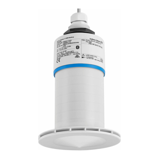
Product description Micropilot FMR20 Modbus RS485 Product description Product design A0028416 1 Device design Device with 40 mm antenna Device with 80 mm antenna Sensor housing Seal Process connection rear side Cable gland Pipe adapter O-ring Counter nut Design ring... -
Page 9: Product Identification
‣ Enter the serial number from the nameplate into the Endress+Hauser Operations App or use the Endress+Hauser Operations App to scan the 2-D matrix code (QR Code) provided on the nameplate All the information about the measuring device and the scope of the associated Technical Documentation are displayed. -
Page 10: Nameplate
Incoming acceptance and product identification Micropilot FMR20 Modbus RS485 Nameplate Order code: Ser. no.: Ext. ord. cd.: MWP: Tp max: DeviceID: Dev .Rev.: ex works Mat.: if modification Date: see sep. label A0029096 2 Nameplate of Micropilot Manufacturer address... - Page 11 Micropilot FMR20 Modbus RS485 Incoming acceptance and product identification Modification mark 2-D matrix code (QR code) Manufacturing date: year-month Up to 33 characters of the extended order code are indicated on the nameplate. If the extended order code contains additional characters, these cannot be displayed.
-
Page 12: Installation
Installation Micropilot FMR20 Modbus RS485 Installation Installation conditions 5.1.1 Installation types A0030605 3 Wall, ceiling or nozzle installation Wall or ceiling mount, adjustable Mounted at front thread Mounted at rear thread Ceiling installation with counter nut (included in delivery) - Page 13 Micropilot FMR20 Modbus RS485 Installation A0028413 4 Nozzle installation 80 mm (3 in) antenna 40 mm (1.5 in) antenna The maximum length of the nozzle L depends on the nozzle diameter D. Please note the limits for the diameter and length of the nozzle.
- Page 14 Installation Micropilot FMR20 Modbus RS485 5.1.3 Position for installation on a vessel A0028410 5 Installation position on a vessel • If possible install the sensor so that its lower edge projects into the vessel. • Recommended distance A wall - nozzle outer edge: ~ ¹⁄₆ of the vessel diameter D. Under no circumstances should the device be mounted closer than 15 cm (5.91 in) to the vessel wall.
- Page 15 Micropilot FMR20 Modbus RS485 Installation ° ° ° A0028927 6 Device alignment for installation on a vessel 5.1.5 Beam angle α W = 2 × D × tan α A0033201 7 Relationship between beam angle α, distance D and beamwidth diameter W The beam angle is defined as the angle α, at which the power density of the radar waves...
- Page 16 Installation Micropilot FMR20 Modbus RS485 40 mm (1.5 in) antenna, α 30 ° W = D × 0.54 40 mm (1.5 in) antenna with flooding protection tube, α 12 ° W = D × 0.21 80 mm (3 in) antenna with or without flooding protection tube, α 12 °...
- Page 17 Micropilot FMR20 Modbus RS485 Installation Please contact the manufacturer for further information. 5.1.7 Protective hood For outdoor use, a protective hood is recommended. The protective hood can be ordered as an accessory or together with the device via the product structure "Accessory enclosed".
- Page 18 Installation Micropilot FMR20 Modbus RS485 A0031093 10 Function of flooding protection tube Air pocket O-ring (EPDM) seal Blocking distance Max. level The tube is screwed directly onto the sensor and seals off the system by means of an O-ring making it air-tight.
- Page 19 Micropilot FMR20 Modbus RS485 Installation Navigate to: Setup → Mapping end point This parameter determines the distance up to which the new mapping is to be recorded. Navigate to: Setup → Present mapping Displays the distance up to which a mapping has already been recorded.
- Page 20 Installation Micropilot FMR20 Modbus RS485 A0028412 12 Cantilever installation, with pivot Cantilever with wall bracket Cantilever with mounting frame Cantilever can be turned (e.g., in order to position the device over the center of the flume) 5.1.11 Installation of horizontal mounting bracket for sewer shafts The horizontal mounting bracket for sewer shafts is available as an accessory.
-
Page 21: Post-Installation Check
Micropilot FMR20 Modbus RS485 Installation A0037748 14 Mounting in a shaft, pivotable and adjustable Arm with wall bracket Pivotable and adjustable arm (e.g. to align the device with the center of a channel) Post-installation check Is the device or cable undamaged (visual inspection)? ... -
Page 22: Electrical Connection
The sensor' s Bluetooth® wireless technology communication can be disabled to increase the operating life of the battery. Potential equalization No special measures for potential equalization are required. Various power supply units can be ordered as an accessory from Endress+Hauser. Endress+Hauser... -
Page 23: Connecting The Device
Micropilot FMR20 Modbus RS485 Electrical connection Connecting the device 6.3.1 Block circuit diagram for Modbus RS485 connection The RS485 connection meets the requirements of the RS485-IS specification for use in hazardous environments. DO / A(+) D1 / B(-) A0037751 16... - Page 24 Electrical connection Micropilot FMR20 Modbus RS485 DO / A(+) DO / A(+) D1 / B(-) D1 / B(-) A0038149 17 Block circuit diagram for Modbus RS485 connection, multiple users Power supply Device with Modbus communication Bus termination Modbus master/RTU The bus cable should be a type-A fieldbus cable with a maximum length of 1 200 m (3 937 ft).
-
Page 25: Post-Connection Check
Micropilot FMR20 Modbus RS485 Operability Post-connection check Is the device or cable undamaged (visual inspection)? Do the mounted cables have adequate strain relief? Are the cable glands mounted and firmly tightened? Does the supply voltage match the specifications on the nameplate? ... -
Page 26: Remote Operation Via Modbus Protocol
System integration via Modbus protocol Micropilot FMR20 Modbus RS485 Remote operation via Modbus protocol A0037752 20 Options for remote operation via Modbus protocol Computer with Modbus operating tool (client application, terminal application, etc.) Remote Transmit Unit (RTU) with Modbus (e.g. Fieldgate FXA42) - Page 27 Micropilot FMR20 Modbus RS485 System integration via Modbus protocol 8.1.2 Modbus function codes Function code Action Register type Command type 03 (0x03) Single / multiple read Holding Register Standard 06 (0x06) Single write Holding Register Standard 16 (0x10) Multiple write...
-
Page 28: Measured Variables Via Modbus Protocol
Commissioning and operation Micropilot FMR20 Modbus RS485 Measured variables via Modbus protocol The 8 most important process parameters are mapped as burst parameters to the first addresses in the Modbus address range. This means that these parameters can be read out in one measurement transmission. - Page 29 Micropilot FMR20 Modbus RS485 Commissioning and operation 9.1.2 SmartBlue system requirements SmartBlue system requirements SmartBlue is available as a download from the Google Play Store for Android devices and from the iTunes Store for iOS devices. • Devices with iOS: iPhone 4S or higher from iOS 9;...
- Page 30 Commissioning and operation Micropilot FMR20 Modbus RS485 A0029486 22 Envelope curve display (sample) in SmartBlue for Android Record video Create screenshot Display mapping menu Start/stop video recording Move time on time axis A0029487 23 Envelope curve display (sample) in SmartBlue for iOS...
-
Page 31: Configuring Level Measurement Via Operating Software
Micropilot FMR20 Modbus RS485 Commissioning and operation Configuring level measurement via operating software 100% A0028417 24 Configuration parameters for level measurement in liquids Reference point of measurement Distance Level Empty calibration (= zero point) Full calibration (= span) BD Blocking distance 9.2.1... -
Page 32: Flow Measurement Configuration
Commissioning and operation Micropilot FMR20 Modbus RS485 Navigate to: Setup → Present mapping Displays the distance up to which a mapping has already been recorded Setup → Confirm distance Navigate to: Setup → Level Shows the level L measured 10. -
Page 33: Measuring Mode
Micropilot FMR20 Modbus RS485 Diagnostics and troubleshooting Measuring mode The following measuring modes are possible: • The continuous mode (standard mode) The device measures continuously once per second. • The single-shot mode The device only performs one measurement and afterwards goes to a mode with reduced power consumption. -
Page 34: Error - Smartblue Operation
Diagnostics and troubleshooting Micropilot FMR20 Modbus RS485 Error Possible cause Remedy Display values not plausible SmartBlue and Modbus active Log off Modbus and disconnect (linearization) simultaneously Log off SmartBlue and disconnect (connection via SmartBlue has priority) Linearized output value not... -
Page 35: Diagnostic Event In The Operating Tool
Micropilot FMR20 Modbus RS485 Diagnostics and troubleshooting 10.3 Diagnostic event in the operating tool If a diagnostic event is present in the device, the status signal appears in the top left status area of the operating tool along with the corresponding symbol for the event level in accordance with NAMUR NE 107: •... - Page 36 *71473147* 71473147 www.addresses.endress.com...