Endress+Hauser FMR 231 Operating Instructions Manual
Micropilot
microwave
level measurement
Hide thumbs
Also See for FMR 231:
- Technical information (44 pages) ,
- Operating instructions manual (92 pages) ,
- Operating instructions manual (68 pages)
Table of Contents
Advertisement
BA 171F/00/en/06.01
Software version 2.0
017479-1000
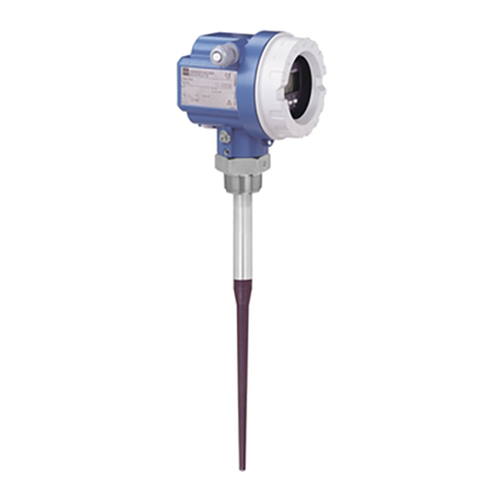
micropilot
FMR 231
Microwave
Level Measurement
Operating Instructions
E N
D R
M IC
E S
O rd
S +
e r
R O
C o
H A
S e
P IL
r. -N
d e :
U S
O T
o .:
E R
II
M e
s s b
M e
e re
a s u
ic h
ri n g
ra n
g e
U 1
m a
6 .. .3
x . 2
4 .. .2
6 V
0 m
0 m
D C
A
IP
6 5
T
A
> 7 0
°C
:
t > 85
°C
+
Endress
The Power of Know How
E N
D R
M IC
E S
O rd
S +
e r
R O
C o
H A
S e
P IL
r. -N
d e :
U S
O T
o .:
E R
II
M e
s s b
M e
e re
a s u
ic h
ri n g
ra n
g e
U 1
m a
6 .. .3
4 .. .2
x . 2
6 V
0 m
0 m
D C
A
IP
6 5
T
A
> 7 0
°C
:
t > 85
°C
Hauser
Advertisement
Table of Contents

Related Manuals for Endress+Hauser FMR 231


Summary of Contents for Endress+Hauser FMR 231
- Page 1 BA 171F/00/en/06.01 micropilot Software version 2.0 017479-1000 FMR 231 Microwave Level Measurement Operating Instructions M IC O rd P IL r. -N d e : o .: s s b e re a s u ic h ri n g ra n 6 ..
- Page 2 Short Instructions Micropilot FMR 231 Short Instructions Note! • The datum point for the empty distance "E" is always the lower face of the process connection. • The full distance "F" can extend up to the tip of antenna. Note! •...
-
Page 3: Table Of Contents
Micropilot FMR 231 Table of Contents Table of Contents Notes on Safety ... Trouble-Shooting ..35 Self-monitoring ..35 Introduction . - Page 4 Micropilot FMR 231 Software History Software History Software Manual Device/ Software revision Changes in manual version version Software 02.98 2310 Original software operable with Commuwin II, from software version 1.41 HART handheld from software version 1.11 with DD version 1.0 11.98...
-
Page 5: Notes On Safety
FCC approved devices operate at 6.3 GHz. Its low pulse power of 1 mW (1 µW ERP) allows safe installation in metallic and non-metallic vessels, with no risk to humans or the environment. The Micropilot FMR 231 has been designed to operate safely in accordance with current Installation, commissioning, technical, safety and EU standards. - Page 6 Notes on Safety Micropilot FMR 231 Safety Conventions and Symbols In order to highlight safety-relevant or alternative operating procedures in the manual, the following conventions have been used, each indicated by a corresponding icon in the margin. Safety conventions Symbol...
-
Page 7: Introduction
Micropilot FMR 231 Chapter 1 Introduction Introduction The Micropilot FMR 231 is a loop-powered transmitter. It is used to for continuous Application non-contact level measurement of liquids, pastes and sludges. It is suitable for use in: • storage tanks, buffer tanks and stilling wells with few internal fittings and where the product surface is generally calm. -
Page 8: Measurement Principle
Chapter 1 Introduction Micropilot FMR 231 Measurement principle datum point datum point inactive beam length launched here max. level Fig. 1.2 Microwave measurement principle Micropilot is a "downward looking" time-of-flight system which measures the distance from the probe mounting (top of the tank) to the surface of the process medium. - Page 9 The accuracy of Micropilot FMR 231 is dependent upon the set measuring range and Accuracy material being measured, see Technical Data. Under reference conditions it is capable of measuring to an accuracy of ±15 mm up to a measuring range of 10 m and ±0.15%...
-
Page 10: Measuring System
Chapter 1 Introduction Micropilot FMR 231 Measuring system 4...20 mA with HART Version with passive 4...20 mA current output and superimposed HART digital loop power signal. • Can be operated either on-site or remotely with the HART handheld 4...20 mA DXR 275. -
Page 11: Installation
Micropilot FMR 231 Chapter 2 Installation Installation Mounting in a tank General notes The microwaves should arrive unhindered at the product surface. • Every object within the beam gives an echo. The nearer the object, the stronger the echo. •... - Page 12 Chapter 2 Installation Micropilot FMR 231 Mounting position The ideal mounting position is as follows: • • not in the middle of the tank no fittings in beam • • not above the filling stream avoid vibration, direct high-pressure cleaning and lateral loads.
- Page 13 Micropilot FMR 231 Chapter 2 Installation Caution! • Applications in hazardous areas: electrostatic charging, e.g. rubbing clean, must be avoided for standard PTFE and PTFE-clad antennas. • Caution! Always tighten the locking screw, since this connects the antenna to the ground potential of the housing.
-
Page 14: Mounting In Stilling Wells
Chapter 2 Installation Micropilot FMR 231 Mounting in stilling wells Installation Mount the antenna perpendicular and in ground terminal the centre of the well. spring locking screw washer • Slight unevenness of the well surface or cladded datum point for... -
Page 15: Protective Cover
Micropilot FMR 231 Chapter 2 Installation Protective cover A protective cover is available for outdoor mounting, Part No. 543199-0001. The scope of delivery comprises the cover and clamping ring. protective cover M IC M IC O rd O rd S er... -
Page 16: Connection
Chapter 3 Connection Micropilot FMR 231 Connection Housing F12 Nameplate Housing T12 ENDRESS+HAUSER MICROPILOT II Order Code: FMR231-CEGGJ1A1A IP 65 Ser.-No.: PIZ0187 Messbereich max. 20 m EEx ia Measuring range 2x cable entries PN max 15 bar ground max. 150°C... -
Page 17: Wiring Examples
Micropilot FMR 231 Chapter 3 Connection Wiring examples The following figures show wiring examples for typical applications: In general: • If possible, ground both ends of the signal line screening. If this is not possible, ground at the sensor side only. -
Page 18: Operation
Chapter 4 Operation Micropilot FMR 231 Operation On-site operation Operating and display module VU 330 not present with housing device operating keys measured matrix position Terminal indicator communication fault – + – + bargraph (current output/edho quality) green LED Fig. 4.1... - Page 19 Micropilot FMR 231 Chapter 4 Operation Fig. 4.2 Matrix operation using the operating and display module VU 330 If the Micropilot is equipped with an operating and display module VU 330, then it is Operation with the VU 330 operated via a 10 x 10 operating matrix.
-
Page 20: Remote Operation
Note! • The HART device description Version 2.0 for Micropilot FMR 231 must be loaded in the DXR 275 before the device can be operated by the handheld. Updates of the device descriptions can be obtained from Endress+Hauser. - Page 21 If the device keys are used to lock the matrix, then parameters cannot be entered remotely via communication. Note! • The Micropilot FMR 231 device description Version 2.0 is required for operation with Commuwin II, see Operating Instructions BA 124F. Endress+Hauser...
- Page 22 Up-/Download This function allows the parameters of an already configured Micropilot FMR 231 to be loaded and stored in Commuwin II. If several Micropilots (with the same software version) have to be configured in the same way, the parameters can now be downloaded into the devices.
-
Page 23: On-Site Calibration Without Display Vu 330
Micropilot FMR 231 Chapter 5 On-site calibration without display VU 330 On-site calibration without display VU 330 100% 20 mA Test path free of obstacles and with reflector, e.g., a wall stable seating for Micropilot 90° height above 4 mA ground approx. - Page 24 Chapter 5 On-site calibration without display VU 330 Micropilot FMR 231 • Correction of measuring The device must have been calibrated range and the echoes suppressed before the measuring range can be corrected. • The new empty distance "E" may not exceed that used for the calibration.
-
Page 25: Calibration With Display/Remote Operation
Micropilot FMR 231 Chapter 6 Calibration with Display/Remote Operation Calibration with Display/Remote Operation The chapter describes the basic calibration and other functions that can be set via the operating matrix. The matrix can be accessed via: • Operating and display module VU 330 •... -
Page 26: Basic Calibration For Tanks
Chapter 6 Calibration with Display/Remote Operation Micropilot FMR 231 Basic calibration for tanks After resetting the Micropilot to the factory settings (only required during commissioning), enter the following parameters: • empty distance E, full distance F and application parameter A. - Page 27 Micropilot FMR 231 Chapter 6 Calibration with Display/Remote Operation Procedure A Entry Significance Echo is level echo Extended calibration V3H0 2: up to echo V3H1 **** Register value when display flashes Wait approx. 3 minutes until the fault indicator disappears.
-
Page 28: Basic Calibration For Bypass Pipes And Stilling Wells
Chapter 6 Calibration with Display/Remote Operation Micropilot FMR 231 Basic calibration for bypass pipes and stilling wells: After resetting the Micropilot to the factory settings (only required during commissioning), enter the following parameters: • empty distance E, full distance F, application parameter A, microwave factor MF. - Page 29 Micropilot FMR 231 Chapter 6 Calibration with Display/Remote Operation • False echo suppression With the tank empty, check whether distance displayed in V0H8 corresponds to the distance to the product surface "D". Entry Significance Empty vessel as far as possible...
-
Page 30: Linearisation
Chapter 6 Calibration with Display/Remote Operation Micropilot FMR 231 Linearisation Linearisation mode A linearisation describes the relationship between level and the tank volume or product weight and allows a measurement in technical units, e.g. metres, hectolitre, tonnes etc. Afterwards, the measured value is displayed in the selected units in V0H0 and the analogue output is proportional to the volume or weight. - Page 31 Micropilot FMR 231 Chapter 6 Calibration with Display/Remote Operation For tanks with a linear dependency between level and volume or weight, technical units Linear dependency can be set by entering the maximum volume or weight in V2H5 and V0H6. Entry...
- Page 32 Chapter 6 Calibration with Display/Remote Operation Micropilot FMR 231 Horizontal cylinder A linearisation curve for a horizontal cylinder can also be entered manually by using the table below: • Starting at the completely full tank (level/volume = 100%, calculate the % volume for each level point.
-
Page 33: Analogue Output
Micropilot FMR 231 Chapter 6 Calibration with Display/Remote Operation Analogue output The analogue output can be set using the fields listed below. If required, a scaling or inversion of the output can be set in V0H5 and V0H6. Settings Field... -
Page 34: Safety Functions
Chapter 6 Calibration with Display/Remote Operation Micropilot FMR 231 Safety functions The Micropilot offers the user the following safety functions: Field Parameter Significance V3H5 Window suppression Defines a distance measured from the datum point in which no echoes are measured. It is used for suppressing strong echoes in the immediate vicinity of the antenna, see Chapter 7.7. -
Page 35: Locking/Unlocking The Matrix
Micropilot FMR 231 Chapter 6 Calibration with Display/Remote Operation Locking/unlocking the matrix After all parameters have been entered, the matrix can be locked. • On-site with the device keys, see Chapter 5, or • via the matrix by entering a three digit code not equal to 333 in V9H9. -
Page 36: Measuring Point Information
Chapter 6 Calibration with Display/Remote Operation Micropilot FMR 231 Measuring point information The following information about the measuring point can be read: Matrix field Display (or entry) Measured value V0H0 Principle measured value V0H8 Distance to product surface Bargraph shows echo quality: 1 segment = 5 dB... -
Page 37: Trouble-Shooting
Micropilot FMR 231 Chapter 7 Trouble-Shooting Trouble-Shooting When the instructions in the manual have been followed correctly, the system must now function. Should this not be the case, the Micropilot provides a number of possibilities for analysing and correcting faults. -
Page 38: Error Messages
Chapter 7 Trouble-Shooting Micropilot FMR 231 Error messages Error messages can be read with communication (DXR 275 or Commuwin II) or the display module only. The current error code is displayed in V9H0. • The last error code is displayed in V9H1. -
Page 39: Fault Analysis
Micropilot FMR 231 Chapter 7 Trouble-Shooting Fault analysis Table 7.2 lists the most common measuring errors with possible remedies. If the first measure is successful, the remaining steps are not required. Fault Analogue output Possible reason Remedy Measured value incorrect... - Page 40 Chapter 7 Trouble-Shooting Micropilot FMR 231 Fault Analogue output Possible reason Remedy Measured value jumps to Multiple echoes If possible, increase first echo factor lower values despite constant page 35 level 20 mA Optimise alignment page 36 expected If necessary, remount Micropilot in a...
-
Page 41: Application Parameter
Micropilot FMR 231 Chapter 7 Trouble-Shooting Application parameter The application parameter that is entered during calibration sets the various elements of Application parameter the signal evaluation such that the Micropilot is ideally matched to the application. Parameters are set in both the operating and the service level. -
Page 42: Echo Quality
Chapter 7 Trouble-Shooting Micropilot FMR 231 Echo quality The echo quality of the measurement is displayed in dB in V3H2 and via the bargraph in V0H8 and V0H9. In this case, each segment represents 5 dB. For devices without communication (operating and display module VU 330, DXR 275 or Commuwin II), the echo quality cannot be checked. -
Page 43: False Echo Suppression
Micropilot FMR 231 Chapter 7 Trouble-Shooting False echo suppression The factory setting is evaluation mode 0. It is strongly recommended that a customer Evaluation mode echo suppression map is recorded, see Chapter 6.1 and 6.2. Evaluation mode V3H0 Significance 0: Factory false echo Recorded at the fatory and is active across the entire measuring range. -
Page 44: Window Suppression
Chapter 7 Trouble-Shooting Micropilot FMR 231 Window suppression In the case of strong echoes from fittings or welds near to the antenna, all echoes within a window B below the antenna tip can be suppressed • The datum point for the window B is the lower face of the process connection. -
Page 45: Simulation
Micropilot FMR 231 Chapter 7 Trouble-Shooting Simulation Where appropriate, the simulation function allows the linearisation and analogue output to be tested. The following possibilities exist: • Simulation of level: fields V0H0, V0H9 and V9H8 follow the set values. • Simulation of volume: fields V0H0, V0H9 and V9H8 follow the set values. -
Page 46: 7.10 Reset
Chapter 7 Trouble-Shooting Micropilot FMR 231 7.10 Reset On reset to factory parameters (Code 333), the values in square brackets [] are assumed. The values in the grey fields are retained. • A customer echo suppression map is switched to the factory map: by setting V3H0 = 1, it can be activated again. -
Page 47: Maintenance And Repair
If necessary, record a new echo suppression map, see Chapter 6.3. A new echo suppression map must be made if the antenna is exchanged. Repairs Should the transmitter need to be repaired by Endress+Hauser, please send it to your nearest service station with a note containing the following information: •... -
Page 48: Spare Parts
Chapter 8 Maintenance and Repair Micropilot FMR 231 Spare parts Installation instructions are packed with the spare part. Modification nameplate When spare parts which are part of the product structure (Chapter 9.3/9.4) are ordered, it must be checked whether the type designation on the nameplate is still valid, e.g. for •... - Page 49 Micropilot FMR 231 Chapter 8 Maintenance and Repair Premounted housing assembly with nameplate, see note on page 42 Housing F12 Standard/EEx ia 543120-0021 Pg13 cable gland 543120-0022 G ½ cable entry 543120-0023 ½ NPT cable entry 543120-0024 M 20x1.5 cable entry...
- Page 50 Chapter 8 Maintenance and Repair Micropilot FMR 231 Premounted housing assembly with nameplate, see note on page 42 Housing T12: Standard/EEx e m 543180-0021 Pg13 cable gland 543180-0022 G ½ cable entry 543180-0023 ½ NPT cable entry 543180-0024 M 20x1.5 cable entry...
-
Page 51: Technical Data
Chapter 9 Technical Data Technical Data General information Manufacturer Endress+Hauser Instrument designation Micropilot FMR 231 E or FMR 231 A Application Continuous level measurement of liquids in tanks and stilling wells Function and system design Measurement prinicple Pulsed time-of-flight via microwave method (PTOF) Evaluation Measuring cycle 2 Hz, evaluation with interference echo suppression. - Page 52 Chapter 9 Technical Data Micropilot FMR 231 Operating conditions (cont.) Environment Operating temperature F12 housing: Standard –40°C...+80°C; EEx ia (T6) –40°C...+50°C range T12 housing: Standard –40°C...+80°C; EEx e (T6) –40°C...+50°C For other temperature classes see appropriate certificate Limiting temperature –40°C...+80°C...
- Page 53 Class I, Division 1, Group A–D CSA XP Class I, Division 1, Group A–D Telecommuncation BZT approval G133414J, FCC LCG FMR23x CE Mark In attaching the CE Mark, Endress+Hauser confirms that the device conforms to all relevant EU directives Endress+Hauser...
-
Page 54: Dimensions
Chapter 9 Technical Data Micropilot FMR 231 Dimensions Endress+Hauser... -
Page 55: Derating Diagrams
Micropilot FMR 231 Chapter 9 Technical Data Derating diagrams Permissible process pressure as a function of flange temperature PTFE antenna with uncladded flange PPS antenna PTFE antenna flange temperature (process side) °C flange temperature (process side) °C Permissible ambient temperature as a... -
Page 56: Product Structure Fmr 231E
Chapter 9 Technical Data Micropilot FMR 231 Product structure FMR 231E Certificate Type Explosion Protection Housin g Standard none ATEX II 1/2 G EEx ia IIC T3...T6 ATEX II 1/2 G EEx e m IIC T3...T6 TIIS Ex ia IIC T3... -
Page 57: Product Structure Fmr 231A
Micropilot FMR 231 Chapter 9 Technical Data Product structure FMR 231A Certificate Type Explosion Protection Housing Operating frequency Standard none 5.8 GHz Standard none 6.3 GHz (FCC approval) FM IS Cl. I, Div. 1, Group A–D 6.3 GHz (FCC approval) FM XP Cl. -
Page 58: 10 Operating Matrix
Chapter 10 Operating Matrix Micropilot FMR 231 10 Operating Matrix 10.1 Matrix operation Basic Measured "Empty" "Full" Application Output damping Value for Value for Safety alarm Measured Level before value calibration vcalibration 0: Tank 7 m 4 mA 20 mA... -
Page 59: Hart
Micropilot FMR 231 Chapter 10 Operating Matrix 10.2 HART Matrix Group Select 3 (H2) 4 (H3) 5 (H4) 6 (H5) 7 (H6) 8 (H7) 9 (H8) 10 (H9) 1 (H0) 2 (H1) Output Safety Measured Measured Empty Full Application Value for... -
Page 60: Index
Index Micropilot FMR 231 Index 20 mA value ..... 31 Maintenance .... - Page 64 Belorgsintez Canada Poland Minsk Singapore Endress+Hauser Ltd. Endress+Hauser Polska Sp. z o.o. Tel. (01 72) 50 84 73, Fax (01 72) 50 85 83 Endress+Hauser (S.E.A.) Pte., Ltd. Burlington, Ontario Warszawy Singapore Tel. (9 05) 6 81 92 92, Fax (9 05) 6 81 94 44 Tel.