Graco Reactor E-10 Instructions-Parts List Manual
Plural component proportioner
Hide thumbs
Also See for Reactor E-10:
- Instructions-parts list manual (74 pages) ,
- Instructions manual (72 pages) ,
- Instructions-parts list manual (58 pages)
Table of Contents
Advertisement
Quick Links
Instructions - Parts List
For spraying or dispensing 1:1 mix ratio materials, including epoxies, polyurethane
foam, polyurea coatings, and joint fill materials. For professional use only.
Not approved for use in European explosive atmosphere locations.
Important Safety Instructions
Read all warnings and instructions in this manual
before using the equipment. Save these
instructions.
See page 4 for a list of models and maximum working pressures.
Heated Package, with Fusion
Nonheated Package, MD2 Cold Spray
™
Gun
Gun
311075ZAB
EN
Advertisement
Table of Contents
Troubleshooting

Related Manuals for Graco Reactor E-10


Summary of Contents for Graco Reactor E-10
- Page 1 Instructions - Parts List 311075ZAB For spraying or dispensing 1:1 mix ratio materials, including epoxies, polyurethane foam, polyurea coatings, and joint fill materials. For professional use only. Not approved for use in European explosive atmosphere locations. Important Safety Instructions Read all warnings and instructions in this manual before using the equipment.
-
Page 2: Table Of Contents
Connect the Main Air Supply ....18 Graco Information......68 Flush Before First Use . -
Page 3: Related Manuals
Related Manuals Related Manuals The following manuals are for Reactor E-10 components and accessories. Some are supplied with your package, depending on its configuration. Manuals are also available at www.graco.com. Manual in Manual in English Description English Description Fusion Mechanical Purge Spray Gun... -
Page 4: Models
Models Models The model number, series letter, and serial number are located on the back of the Reactor E-10. For faster assistance, please have that information ready before calling Customer Service. Maximum Working Bare Pressure, Proportioner * Electrical Part, Series... -
Page 5: Warnings
Warnings Warnings The following warnings are for the setup, use, grounding, maintenance, and repair of this equipment. The exclamation point symbol alerts you to a general warning and the hazard symbols refer to procedure-specific risks. When these symbols appear in the body of this manual or on warning labels, refer back to these Warnings. Product-specific hazard symbols and warnings not covered in this section may appear throughout the body of this manual where applicable. - Page 6 Warnings WARNING SKIN INJECTION HAZARD High-pressure fluid from gun, hose leaks, or ruptured components will pierce skin. This may look like just a cut, but it is a serious injury that can result in amputation. Get immediate surgical treatment. • Engage trigger lock when not spraying.
- Page 7 Warnings WARNING THERMAL EXPANSION HAZARD Fluids subjected to heat in confined spaces, including hoses, can create a rapid rise in pressure due to the thermal expansion. Over-pressurization can result in equipment rupture and serious injury. • Open a valve to relieve the fluid expansion during heating. •...
- Page 8 Warnings WARNING MOVING PARTS HAZARD Moving parts can pinch, cut or amputate fingers and other body parts. • Keep clear of moving parts. • Do not operate equipment with protective guards or covers removed. • Equipment can start without warning. Before checking, moving, or servicing equipment, follow the Pressure Relief Procedure and disconnect all power sources.
-
Page 9: Important Isocyanate (Iso) Information
Important Isocyanate (ISO) Information Important Isocyanate (ISO) Information Isocyanates (ISO) are catalysts used in two component materials. Isocyanate Conditions Spraying or dispensing fluids that contain isocyanates creates potentially harmful mists, vapors, and atomized particulates. • Read and understand the fluid manufacturer’s warnings and Safety Data Sheets (SDSs) to know specific hazards and precautions related to isocyanates. -
Page 10: Material Self-Ignition
Important Isocyanate (ISO) Information Material Self-Ignition NOTE: The amount of film formation and rate of crystallization varies depending on the blend of ISO, the humidity, and the temperature. Foam Resins with 245 fa Some materials may become self-igniting if applied Blowing Agents too thick. -
Page 11: Overview
• Slow circulation results in a higher temperature transfer in the heater, so hoses and gun heat up The Reactor E-10 is gravity-fed from 7 gal. (26.5 liter) quicker. supply tanks mounted on the unit. The tanks are •... -
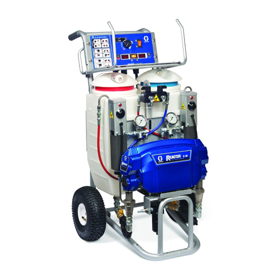
Page 12: Component Identification
Component Identification Component Identification . 1: Component Identification, Heated Packages (Part Number AP9572 Shown) Desiccant Dryer (mounts on supply tank A) Supply Tank A Recirculation Tubes Supply Tank B Air Line Inlet (quick-disconnect fitting) Pump A Outlet Hose Connections Pump B Return Hose Connections Heater A Fluid Temperature Sensors... - Page 13 Component Identification . 2: Component Identification, Nonheated Packages (Part Number 249808 Shown) Supply Tank A Desiccant Dryer (mounts on supply tank A) Supply Tank B Recirculation Tubes Pump A Air Line Inlet (quick-disconnect fitting) Pump B Outlet Hose Connections Heater A Hose Rack and Control Shield Heater B Fluid Inlet Ball Valves (1 on each side)
- Page 14 Component Identification Controls and Indicators TI7016a . 3 Controls and Indicators (heated unit shown) Motor/Pump Control Function Knob Table 1: Status Codes (see also the label on back of the control enclosure) Use knob (CF) to select desired function. Code Code Name Icon Setting...
- Page 15 Component Identification Fluid Temperature Sensors and Displays Heater Temperature Controls (HC) See F . 3. Fluid temperature sensors (T) monitor actual Sets temperature of component A and B heaters. temperature of component A and B fluid going to spray Indicator lights (HL) turn on when thermostats are gun.
-
Page 16: Installation
Generator (if used): follow your local code. Start and regulations. stop generator with power cord(s) disconnected. 1. Connect Reactor E-10 to the correct power source for your model. See T 2, page 17. Models with Spray gun: grounded through the supplied fluid hoses,... - Page 17 To avoid electric shock, always unplug both cords before servicing Reactor E-10. Ensure no other high amp loads are connected while running Reactor E-10. To verify separate circuits, plug in Reactor E-10 or a worklight and cycle breakers on and off. Heater Power TI7061a Motor Power .
-
Page 18: Connect The Fluid Hoses
Flush Before First Use 1. For air operated guns: connect the gun air hose to The Reactor E-10 is tested with a plasticizer oil at the the gun air input and to the air filter outlet (Z). factory. Flush out the oil with a compatible solvent before spraying. -
Page 19: Fill The Wet-Cups
Installation Fill the Wet-Cups 3. Remove tank A cover and pour ISO into tank A (red side, with desiccant filter in cover). See F . 7. Keep the felt washers in the pump wet-cups saturated with ISO pump oil. The lubricant creates a barrier between the ISO and the atmosphere. -
Page 20: Purge Air And Flush The Fluid Lines
Installation Purge Air and Flush the Fluid NOTICE Lines To prevent cross-contamination of fluids and equipment parts, never interchange component A (isocyanate) and component B (resin) parts or containers. Have at least two 5 gal. (19 liter) pails to transfer fluid from drums to supply tanks. - Page 21 Installation 8. When clean fluids exit both recirculation tubes (P), set function knob to Park 7. Set function knob to Slow Recirc or Fast Recirc 9. Replace the recirculation tubes in the supply tanks. 10. On non-heated units, purge the hoses through the gun without a static mixer installed.
-
Page 22: Operation
Some models heat the fluid, which can cause equipment surfaces to become very hot. To avoid severe burns: • Do not operate Reactor E-10 without all covers and shrouds in place. • Do not touch hot fluid or equipment. •... -
Page 23: Heatup Guidelines
Operation 6. Adjust the heater control knobs as necessary for a stable spray temperature. Table 4: Heatup Time Guidelines for starting a cold machine with 5 gal. (19 l) per side (see Notes below) Fluid Spray Target 35 ft (10.7 m) Hose 70 ft (21 m) Hose Temperature (1 bundle) -
Page 24: Heating Foam Resins With 245 Fa Blowing Agents
Operation • For a quicker start, do initial heatup circulation with c. Refill the Tanks, page 26. the tanks 1/4 to 1/3 filled, then add more material. d. Set the Spray valves to Recirc. Heating Foam Resins with 245 fa Blowing Agents New foam blowing agents will froth at temperatures above 90°F (33°C) when not under pressure, especially... -
Page 25: Spraying/Dispensing
Operation Spraying/Dispensing 4. Check the fluid pressure gauges to ensure proper pressure balance. If imbalanced, reduce the pressure of the higher component by slightly turning the Spray valve for that component toward Recirc, until the gauges show balanced pressures. The pressure imbalance alarm (Status Code 1) is inactive for 10 sec after entering spray pressure NOTE: For air operated guns only: Air is supplied to the mode, to allow time to balance pressures. -
Page 26: Pause (Heated Units)
Operation Pause (Heated Units) NOTICE To prevent cross-contamination of fluids and To bring the hose and gun back to spray temperature equipment parts, never interchange component A after a brief break, use the following procedure. (isocyanate) and component B (resin) parts or containers. -
Page 27: Maintenance
Maintenance Maintenance • Check the pump wet-cups fluid level daily, Fill the • Generally, flush if you will shutdown for more than Wet-Cups, page 19. three days. Flush more often if material is moisture sensitive and humidity is high in the storage area, or •... -
Page 28: Flushing
Flushing Flushing 3. For heated units: shut off Heater Power. Allow the system to cool. To avoid fire and explosion, always ground equipment and waste container. To avoid static sparking and injury from splashing, always flush at the lowest possible pressure. Hot solvent may ignite. To avoid fire and explosion: 4. -
Page 29: Purge The Gun Hoses (Nonheated Units Only)
Flushing 8. Wipe out any remaining material from the supply 13. Set the function knob to Park tanks. Fill each supply tank with 1-2 gal. (3.8-7.6 l) of solvent recommended by your material manufacturer. 9. Set the function knob to Fast Recirc . -
Page 30: Troubleshooting
Troubleshooting Troubleshooting Status Codes 3. Check the fluid inlet strainers (51a, page 27) and the fluid filters at gun. Determine the status code by counting the number of 4. Clean or change the restrictor at the mixer manifold times the status indicator (ST) blinks. if using disposable mixer gun kit. - Page 31 Troubleshooting Table 5: Status Code 1 and 2 Settings DIP Switch and Function Left Right (default setting) DIP Switch 1 If selected, causes shutdown or displays a warning if the WARNING SHUTDOWN pressure imbalance exceeds selection made in DIP Switch 2 DIP Switch 2 If selected, causes shutdown if A and B pressure imbalance 500 psi (3.5 MPa, 35 bar)
-
Page 32: Troubleshooting Chart
Troubleshooting Troubleshooting Chart PROBLEM CAUSE SOLUTION Reactor E-10 does not operate. No power. Plug in power cord. Cycle motor power off, then on to reset breaker. Motor does not operate. Power turned on with function knob Set function knob to Park , then set to a run position. - Page 33 Troubleshooting PROBLEM CAUSE SOLUTION One side doesn’t come up to Dirty or damaged Spray valve. Clean or repair, see pressure in spray mode. Recirculation/Spray Valves, page Plugged fluid inlet strainer. Clear, see Maintenance, page 27. Pump intake valve plugged or stuck Clean pump intake valve.
- Page 34 Troubleshooting PROBLEM CAUSE SOLUTION Status indicator (red LED) not lit. Motor Power switch off. Cycle the motor power off, then on to reset breaker. Loose indicator cable. Check that cable is connected at J10 pins 1 (red) and 2 (black) on control board.
- Page 35 Troubleshooting PROBLEM CAUSE SOLUTION No heat, and heater indicator light is Heater Power shut off, or circuit Cycle heater power off, then on to off. breaker tripped. reset circuit breaker. Bad thermostat. With power on, check for continuity at clicks of heater control knob. To replace thermostat, see your heater manual.
-
Page 36: Repair
2. Set the function knob to Park 3. Shut off Motor Power. Disconnect the power supply. NOTE: Use dropcloth or rags to protect Reactor E-10 and surrounding area from spills. 4. Open the filter drain plug on Y-strainer (51). -
Page 37: Recirculation/Spray Valves
Repair Recirculation/Spray Valves 4. Clean and inspect all parts for damage. Ensure that the seat (503a) and gasket (503b) are positioned inside each valve cartridge (503). 5. Apply PTFE pipe sealant to all tapered pipe threads before reassembling. 1. Follow Before Beginning Repair, page 36. 6. -
Page 38: Displacement Pump
Repair Displacement Pump 2. Remove the pump rod cover (222). Push clip up in back and push pin (217) out. 3. Loosen locknut (218) by hitting firmly right-to-left with a non-sparking hammer. 4. Unscrew the pump. See your pump manual for Refer to your displacement pump manual for repair and repair and parts information. -
Page 39: Control Module
Repair Control Module 3. Remove the temperature sensor (424): a. Remove the snap ring (66d) in the thermowell Change Display Temperature Units (°F/°C) housing (66e). b. Pull the sensor (424) and the spacer (66g) out of the thermowell housing. c. Work the sensor and wire out of the cable The unit is shipped with the temperature displays set to °F. - Page 40 Repair Replace Function Knob/Potentiometer 5. See F . 13. Remove the two setscrews (416a) and pull the function knob (416) off of the potentiometer (404) shaft. 6. Remove the nut (N, part of 404) and the detent plate (415). 1. Follow Before Beginning Repair, page 36. 7.
- Page 41 Repair Control Board 5. Disconnect all cables and connectors from the board. Remove two jumper wires (413) from J10 pins 7-8 and 9-10. Power Bootup Check 6. Remove the screws (408) and remove the board from the control module. 7. Install the new board in reverse order. NOTE: Apply thermal compound between the square There is one red LED (D11) on the board.
- Page 42 Repair Heated Models Only LINE Heater Heater Power On/Off LINE (20 A Breaker) Single Cord Models Only Heater Black Twin Flat Cable Motor J11 (120 V Board) Black J4 (240 V Board) CONTROL BOARD Function Yellow 249434 (120 V) Knob Cycle 249432 (240 V) Yellow...
-
Page 43: Fluid Heaters (If Supplied)
Repair Fluid Heaters (if supplied) Pressure Transducers See your heater manual for repair and parts information, 1. Follow Before Beginning Repair, page 36. which is supplied with heated units. 2. Follow the Pressure Relief Procedure, page 22. 1. Follow Before Beginning Repair, page 36. 3. -
Page 44: Drive Housing
Repair Drive Housing Installation 1. Apply grease liberally to the washers (208, 212), bearings (209, 211, 213), gear reducer (214), Removal crankshaft (210), and inside the drive housing (215). Grease is supplied with the replacement parts kits. NOTE: The B side crankshaft (210) includes the cycle counter magnet (224). -
Page 45: Cycle Counter Switch Replacement
Repair Cycle Counter Switch Replacement B side drive housing cover (227) includes the cycle counter switch (223), mounted in the cover. When reassembling, be sure to install cover with switch on B side. 0.6 in. (15.2 mm) from inside edge 1.0 in. -
Page 46: Electric Motor
Repair Electric Motor NOTE: The motor is heavy and may require two people to lift. Test Motor 5. Remove the screws holding the motor to bracket. Lift the motor off unit. If the motor is not locked up by pumps, it can be tested using a 9 V battery. -
Page 47: Fan
Repair 1. Disconnect the fan cable (37) from the fan (202). With Motor Power on, test the cable connector for line voltage (120 V or 240 V). 2. If voltage is correct: the fan is defective. Remove the screws holding the fan to the shield (206). Install TI7030a the new fan in reverse order. -
Page 48: Parts
Parts Parts Part AP9570 or CS9570, 120 V, 15 A, Heated Package Part AP9571 or CS9571, 240 V, 10 A, Heated Package Part AP9572 or CS9572, 240 V, 20 A, Heated Package Proportioner Description AP9570 120 V, 15 A, Heated 249570 249499 249810... - Page 49 Parts Part 249806, 120 V, 15 A, Nonheated Package, MD2 Part 249808, 240 V, 10 A, Nonheated Package, MD2 Part 24R984, 120 V, 15 A, Nonheated Package, 2K Dispense Part 24R985, 240 V, 10 A, Nonheated Package, 2K Dispense 255325 24R021 249633 24R823...
- Page 50 Parts Part 25C350, 240 V, 20 A, OEM Package 311075ZAB...
- Page 51 Parts Part 249570, 120 V, 15 A, Heated Proportioner Part 249571, 240 V, 10 A, Heated Proportioner Part 249572, 240 V, 20 A, Heated Proportioner 311075ZAB...
- Page 52 Parts Heated Proportioners Ref. Part Description Qty. Ref. Part Description Qty. 24L004 DISPLAY, heated, 120 V; Model 24R382 CART; see page 63 249570; see page 60 24L000 TANK, with lid and outlet fitting; 24L005 DISPLAY, heated, 240 V; LDPE; includes item 2a Models 249571 and 249572;...
- Page 53 Parts Ref. Part Description Qty. Ref. Part Description Qty. 15G476 LABEL, components A and B; see 24E555 KIT, temperature sensor page 48 66a‡ 121063 O-RING, fluroroelastomer 119992 NIPPLE, pump inlet; 3/4 npt 66b‡ 123787 FITTING, elbow, 45°; 3/8 jic x 157350 NIPPLE;...
- Page 54 Parts Part 287655, 120 V Bare Proportioner Part 287656, 240 V Bare Proportioner 201 (Ref) ‡221 215‡ 220‡ 207‡ †213 †212 †214 222‡ †213 216 220‡ 207‡ 217 TI6978a Ref. Part Description Qty. Ref. Part Description Qty. 217 196762 PIN, straight 24E355 MOTOR, electric;...
- Page 55 Parts Part 25C350, 240 V, 20 A, OEM Proportioner 311075ZAB...
- Page 56 Parts OEM Proportioner Ref. Part Description Qty. Ref. Part Description Qty. 24K997 CORD, 240 V-20A 24R382 CART, painted, E-10, see page 15G458 CABLE, fan, 46 in. with plug/board conn, see page 51 287656 PROPORTIONER, 240V, E10, see page 51 114601 CONDUIT, flexible, non-metallic 117493 SCREW, mach, hex washer hd...
- Page 57 Parts Part 249576, 120 V, Nonheated Proportioner Part 249577, 240 V, Nonheated Proportioner 40 1 (Ref) 47 38 30 (Ref) 1 (Ref) 64 65 311075ZAB...
- Page 58 Parts Nonheated Proportioners Ref. Part Description Qty. Ref. Part Description Qty. 15G458 CABLE, fan; see page 59 24R382 CART; see page 63 CONDUIT, flexible; non-metallic 24L000 TANK, with lid and outlet fitting; 15G385 COVER, access, display LDPE; includes item 2a 40...
- Page 59 Parts Part 249499, Insulated Hose Bundle With Recirculation Lines 302 (Ref) 303 (Ref) Ref. Part Description Qty. Ref. Part Description Qty. 303 15G342 HOSE, air; 1/4 in. (6 mm) ID; 1/4 301 249508 HOSE, fluid (component A), npsm (fbe); 35 ft (10.7 m) moisture guard;...
- Page 60 Parts Part 24L004, 120 V Heated Display Part 24L005, 240 V Heated Display 416a 416a 404 (Ref) Ref. Part Description Qty. Ref. Part Description Qty. 412 116773 CONNECTOR, plug 401 15F984 PLATE 413 15C866 WIRE, jumper 402 24K983 SWITCH, motor or heater power, 414 15G279 LABEL, display with circuit breaker 415 15G053 PLATE, detent...
- Page 61 Parts Part 249537, 120 V Nonheated Display Part 249538, 240 V Nonheated Display 416a 416a 404 (Ref) TI6983a Ref. Part Description Qty. Ref. Part Description Qty. 411 101765 GROMMET 401 15F984 PLATE 412 116773 CONNECTOR, plug 402 24K983 SWITCH, motor power, with circuit WIRE, jumper breaker 414 15G279 LABEL, display...
- Page 62 Parts Part 24L009 Recirculation Manifold, Heated Models Ref. Part Description Qty. 505b (Blue) 24K993 MANIFOLD, recirculation 111763 ELBOW; 1/4 npt (mbe) 239914 VALVE, Spray; includes items 503a, 503b 503a 15E022 . SEAT 503b 111699 . GASKET 503a 224807 BASE, valve 505a (Red) 512 503b...
- Page 63 Parts Part 249582, Cart Ref. Part Description Qty. 154636 WASHER, flat 116411 SPRING 116477 WASHER, flat; nylon 116478 WHEEL, pneumatic 101242 RING, retaining GRIP, handle 24U760 BRACKET, tank mount 24U761 BRACKET, crossbar 24U762 BRACKET, motor mount 24T150 GUSSET 110996 NUT, hex, flange head 311075ZAB...
-
Page 64: Suggested Spare Replacement Parts
Suggested Spare Replacement Parts Suggested Spare Replacement Parts Keep the following spare parts on hand to reduce downtime. All Units Heated Units Only Part Description Part Description 24K984 DRYER, desiccant 24K981 DISPLAY, temperature, with sensor 15F895 O-RING, lid, tank 24K980 FUSE, heater over-temperature 24K983 SWITCH, motor or heater power, with circuit 24K978 THERMOSTAT, heater breaker... -
Page 65: Dimensions
Dimensions Dimensions All Models ti6974b 311075ZAB... -
Page 66: Technical Specifications
Technical Specifications Technical Specifications Reactor E-10 Plural Component Sprayer Metric Maximum fluid working pressure 2000 psi 14 MPa, 140 bar Maximum fluid temperature 160°F 71°C Maximum ambient temperature 110°F 43°C 5.4 kg/min Maximum Output at 340 cycles/min 12 lb/min Output per Cycle (A and B) 0.00352 gal. - Page 67 Technical Specifications Reactor E-10 Plural Component Sprayer Metric Sound Pressure Measured in fast circulation mode 78.7 dB(A) Measured at 2000psi (14 MPa, 140 bar), 0.72 84.5 dB(A) gpm (2.7 lpm) Air Inlet/Outlet Sizes Air inlet size 1/4 in. quick-disconnect industrial type pin fitting...
-
Page 68: Graco Standard Warranty
With the exception of any special, extended, or limited warranty published by Graco, Graco will, for a period of twelve months from the date of sale, repair or replace any part of the equipment determined by Graco to be defective.