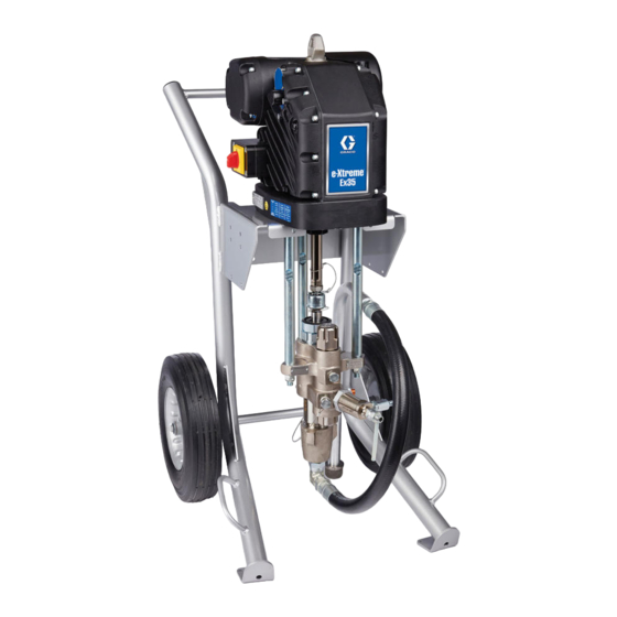
Table of Contents
Advertisement
Quick Links
Installation
Ex35
Ex35 / / / Ex45
Ex35
Ex45 e e e - - - Xtreme®
Ex45
Electric driver
driver for
for application
application of of of finishing
Electric
Electric
driver
for
application
For
For professional
For
professional use
professional
use only.
use
only.
only.
Important
Important Safety
Important
Safety Instructions
Safety
Read all warnings and instructions in this manual and the system
manual before using equipment. Save all instructions.
See pages 3 for model and approvals
information.
Xtreme® Driver
Xtreme®
Driver
finishing materials
materials and
finishing
materials
Instructions
Instructions
PROVEN QUALITY. LEADING TECHNOLOGY.
Driver
and protective
protective coatings
coatings using
and
protective
coatings
3A3165H
using e e e - - - Xtreme
Xtreme Sprayers.
Sprayers.
using
Xtreme
Sprayers.
EN
Advertisement
Table of Contents

Summary of Contents for Graco Ex35
- Page 1 Installation Ex35 Ex35 Ex35 / / / Ex45 Ex45 Ex45 e e e - - - Xtreme® Xtreme® Driver Xtreme® Driver Driver 3A3165H Electric driver driver for for application application of of of finishing finishing materials materials and and protective...
-
Page 2: Table Of Contents
Power Supply Requirements......8 Driver Model ..........3 Hazardous Area Cabling and Conduit Requirements......... 8 Related Manuals ..........3 Grounding ........... 9 Warnings ............4 Connect Power ..........10 Component Identification........7 General Repair Information ......... 11 Installation............8 Graco Information..........12 3A3165H... -
Page 3: Model Information
• EN 60079–0 3A5124 e-Xtreme Driver Operation, Repair • EN 60079–1 and Troubleshooting • ANSI/ISA 60079–0 3A3164 e-Xtreme Ex35/Ex45 Sprayer • ANSI/UL 60079–1 311619 Pump Mounting Kit Manual • FM 3600 • FM 3615 • FM 3810 • CSA C22.2 No. 0.4 •... -
Page 4: Warnings
Damaged parts must be replaced only with genuine Graco parts with no substitutions. • Consult Graco Technical Assistance or your Graco distributor if dimensional information on the flameproof joints is necessary. • Consult Graco Technical Assistance or your Graco distributor for genuine replacement fasteners. - Page 5 Warnings WARNING WARNING WARNING ELECTRIC ELECTRIC ELECTRIC SHOCK SHOCK SHOCK HAZARD HAZARD HAZARD This equipment must be grounded. Improper grounding, setup, or usage of the system can cause electric shock. • Turn off and disconnect power at main switch before disconnecting any cables and before servicing or installing equipment.
- Page 6 Warnings WARNING WARNING WARNING TOXIC TOXIC TOXIC FLUID FLUID FLUID OR OR FUMES FUMES FUMES Toxic fluids or fumes can cause serious injury or death if splashed in the eyes or on skin, inhaled, or swallowed. • Read Safety Data Sheets (SDSs) to know the specific hazards of the fluids you are using.
-
Page 7: Component Identification
Component Identification Component Identification Identification Component Component Identification Ref. Description Ref. Ref. Description Description Driver Lift Ring Oil Drain Plug Driver Output Shaft Oil Sight Glass Status Indicator Light (LED) Pressure Control Knob Oil Fill Cap (vented) Power Switch (Lock-out tag-out equipped) Electrical Junction Box Conduit Entry Electrical Junction Box Cover... -
Page 8: Installation
Installation Installation Installation Installation Hazardous Hazardous Area Hazardous Area Cabling Area Cabling and Cabling and Conduit Conduit Conduit Requirements Requirements Requirements Explosion Proof Proof Explosion Explosion Proof Installation of this equipment involves potentially hazardous procedures. Only trained and qualified All electrical wiring in the hazardous area must be personnel who have read and who understand encased in Class I, Division I, Group D approved the information in this manual should install this... -
Page 9: Grounding
Loosen the ground screw (ZZ) and attach a ground wire (Graco part 244524 – not supplied). Tighten the ground screw securely. Connect the other end of the ground wire to a true earth ground. -
Page 10: Connect Power
Installation Connect Power Power Connect Connect Power 4. Install incoming power wires into the disconnect terminals labeled 2T1 and 4T2, and torque to 7 in-lb (0.8 N•m). 5. Reinstall junction box cover (Z) and screws (J). Torque screws to 15–20 ft-lb (21–27 N•m). Improper wiring may cause electric shock, fire NOTE: One wire is installed in terminals 1L1 and NOTE:... -
Page 11: General Repair Information
Make sure wires are not pinched when re-installing covers. Wires will be damaged and create an electrical hazard and/or fire and explosion hazard if pinched. NOTE: NOTE: Consult Graco Technical Assistance or your NOTE: Graco distributor if dimensional information on the flameproof joints is necessary. 3A3165H... -
Page 12: Graco Information
All written and visual data contained in this document reflects the latest product information available at the time of publication. Graco reserves the right to make changes at any time without notice. Original Instructions. This manual contains English. MM 3A3165...


