
Related Manuals for Garmin GSU 75 Series


Summary of Contents for Garmin GSU 75 Series
- Page 1 GSU 75 ADAHRS Installation Manual 190-01639-00 May, 2017 Revision 6 340095 The document reference is online, please check the correspondence between the online documentation and the printed version.
- Page 2 Garmin. Garmin hereby grants permission to download a single copy of this manual and of any revision to this manual onto a hard drive or other electronic...
- Page 3 The tables are current at the time of publication of this manual (see date on front cover) and are subject to change without notice. Authorized Garmin Sales and Service Centers are encouraged to access the most up-to-date bulletin and advisory information on the Garmin Dealer Resource web site at www.garmin.com using their Garmin-provided user name and password.
- Page 4 GSU 75 (011-03094-00) HARDWARE MOD LEVEL HISTORY SERVICE SERVICE BULLETIN BULLETIN PURPOSE OF MODIFICATION LEVEL NUMBER DATE Operating high temperature reduced to 65°C GSU 75H (011-03094-20) HARDWARE MOD LEVEL HISTORY SERVICE SERVICE PURPOSE OF MODIFICATION LEVEL BULLETIN BULLETIN NUMBER DATE GSU 75B (011-03094-40) HARDWARE MOD LEVEL HISTORY SERVICE SERVICE...
- Page 5 GMU 44 P/N 011-00870-20 HARDWARE MOD LEVEL HISTORY SERVICE SERVICE BULLETIN BULLETIN PURPOSE OF MODIFICATION LEVEL NUMBER DATE 190-01639-00 GSU 75 ADAHRS Installation Manual Rev. 6 Page iii 340095 The document reference is online, please check the correspondence between the online documentation and the printed version.
-
Page 6: Table Of Contents
TABLE OF CONTENTS PARAGRAPH PAGE Section 1 GENERAL DESCRIPTION .............1-1 1.1 Introduction........................1-1 1.2 Equipment Description ....................1-2 1.3 Interface Summary......................1-3 1.4 Technical Specifications ....................1-3 1.5 Certification ........................1-6 1.6 Operating Instructions...................... 1-8 1.7 Reference Documentation....................1-8 Section 2 INSTALLATION OVERVIEW............2-1 2.1 Introduction........................ -
Page 7: Paragraph Page
PARAGRAPH PAGE 4.8 GSU 75 System ID Inputs ....................4-9 Section 5 POST INSTALLATION, CONFIGURATION, AND CHECKOUT PROCEDURE 5.1 Function Selector Switches and Display ................. 5-1 5.2 Post-Installation Calibration Procedures ................. 5-1 5.3 Calibration Procedure A-1: Pitch/Roll Offset Compensation by Aircraft Leveling..5-3 5.4 Calibration Procedure A-2: Zero Pitch/Roll Offsets by Manual Entry ...... - Page 8 LIST OF FIGURES FIGURE PAGE Section 1 GENERAL DESCRIPTION .............1-1 Figure 1-1. GSU 75 Unit View (in rack) ................1-1 Section 2 INSTALLATION OVERVIEW............2-1 Figure 2-1 GSU 75 Air Hose Fitting Locations..............2-4 Figure 2-2 GSU 75 with Mounting Rack................2-7 Section 3 INSTALLATION PROCEDURE .............3-1 Figure 3-1 Insulation to Pin/Socket Clearance ..............
- Page 9 LIST OF TABLES TABLE PAGE Section 1 GENERAL DESCRIPTION .............1-1 Table 1-1 GSU 75 with 117-00608-00 Rack ............... 1-3 Table 1-3 Physical Characteristics GMU 44 (011-00870-20) ..........1-4 Table 1-2 Physical Characteristics GMU 44 (011-00870-00, 011-00870-10) ..... 1-4 Table 1-4 General Specifications..................1-5 Table 1-5 Power Requirements....................
- Page 10 TABLE PAGE Table 4-10 GSU 75 RS-422 I/O ................... 4-7 Table 4-11 GMU 44 RS-422 I/O ..................4-7 Table 4-12 GSU 75 Discrete Inputs..................4-7 Table 4-13 GSU 75 OAT Probe I/O ..................4-8 Table 4-14 GSU 75 PPS Inputs .................... 4-8 Table 4-15.
-
Page 11: Section 1 General Description
Garmin recommends installation of the GSU 75 and GMU 44 by a Garmin-authorized installer. To the extent allowable by law, Garmin will not be liable for damages resulting from improper or negligent installation of the GSU 75 and GMU 44. For questions, please contact Garmin Aviation Product Support at 1-888-606-5482. -
Page 12: Equipment Description
1.2.1 GSU 75 The Garmin GSU 75 ADAHRS (Air Data, Attitude and Heading Reference System) is a remote mounted device that provides flight altitude, airspeed, attitude and heading data for flight instrumentation. The GSU 75 provides the following information in ARINC 429 format: •... -
Page 13: Interface Summary
2 Aircraft Power Inputs 1.4 Technical Specifications 1.4.1 Environmental Qualification Form The Environmental Qualification Forms are available directly from Garmin under the following part numbers: GSU 75 Environmental Qualification Form, Garmin part number 005-00770-01 GMU 44 Environmental Qualification Form, Garmin part number 005-00164-31 Physical Characteristics 1.4.2... -
Page 14: Table 1-2 Physical Characteristics Gmu 44 (011-00870-00, 011-00870-10)
Table 1-2 Physical Characteristics GMU 44 (011-00870-00, 011-00870-10) Specification Characteristic 0.35 lbs. (0.16 kg), unit only GMU 44 Weight 0.50 lbs. (0.23 kg), installed with rack and connectors Physical Dimensions: Height: 2.10 inches (53.3 mm), excluding pigtail) GMU 44 3.35 inches (85.1 mm), diameter including flange Table 1-3 Physical Characteristics GMU 44 (011-00870-20) Specification Characteristic... -
Page 15: Table 1-4 General Specifications
1.4.3 General Specifications Table 1-4 contains general environmental specifications. For detailed specifications, see the applicable Environmental Qualification Forms. NOTE The GSU 75 may require a warm-up period of 15 minutes to reach full accuracy (30 minutes if the environmental temperature is less that 0 °... -
Page 16: Certification
1.5 Certification The conditions and tests required for the TSO approval of this article are minimum performance standards. It is the responsibility of those installing this article either on or within a specific type or class of aircraft to determine that the aircraft installation conditions are within the TSO standards. TSO articles must have separate approval installation in an aircraft. -
Page 17: Table 1-8 Tso Deviations For Gsu 75 (011-03094-X0)
1.5.2.1 GSU 75 (011-03094-X0) Table 1-8 TSO Deviations for GSU 75 (011-03094-X0) Deviation 1. Garmin has been granted a deviation from TSO-C106 to use Society of Automotive Engineers (SAE) AS 8002 Rev A instead of SAE AS 8002 as the Minimum Performance Standard. -
Page 18: Operating Instructions
TSO-C6d 3. Garmin was granted a deviation from TSO-C6d to use SAE AS 8013A instead of SAE AS 8013 as the Minimum Performance Standard. 4. Garmin was granted a deviation from TSO-C6d to list this secondary TSO in the Installation Manual rather than on the article itself. -
Page 19: Section 2 Installation Overview
*Garmin recommends the GMU 44 (011-00870-10 & 011-00870-20) with Installation Rack (115-00481-10) for new TC/STC approvals. Garmin does not recommend the GMU 44 (011-00870-00) for new TC/STC approvals. The GMU 44 (011-00870-10) maintains the same form, fit, and function as the original GMU 44 (011-00870-00), the GMU 44 (011-00870-20) unit has smaller vertical clearance requirements than the GMU 44 (011-00870-00 and 011-00870-10) units. -
Page 20: Equipment Available
2.3 Equipment Available Each of the accessories listed in Table 2-4 are available separately for the GSU 75. Table 2-4 GSU 75 Accessories Item Garmin Catalog Part Number GSU 75 Unit Rack 117-00608-00 GSU 75 Connector Kit 011-03109-00 Each of the accessories listed in Table 2-4 are available separately for the GMU 44. -
Page 21: Additional Equipment Required
1/8-27 ANPT brass fitting for each pitot and static port. Use appropriate aircraft fittings to connect to pitot and static system lines. • #18 or #20 AWG wire contacts, Garmin part number 336-00044-00 (only required if #18 or #20 AWG wire is used) 2.5 Cabling and Wiring... -
Page 22: Pneumatic Plumbing
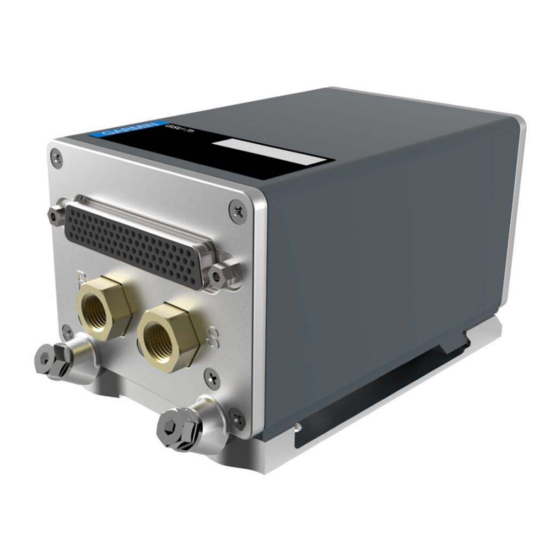
2.7 Pneumatic Plumbing The GSU 75 has two stainless steel ports that are connected to the aircraft’s pitot pressure source and static pressure source. The two ports are labeled on the unit (Figure 2-1). The pressure ports have 1/8-27 ANPT female threads. -
Page 23: Installation Approval Considerations For Pressurized Aircraft
2.10 Installation Approval Considerations for Pressurized Aircraft Cable installations on pressurized cabin aircraft require FAA approved installation design and engineering substantiation data whenever such installations incorporate alteration (penetration) of the cabin pressure vessel by connector holes and/or mounting arrangements. For needed engineering support pertaining to the design and approval of such pressurized aircraft installations, it is recommended that the installer proceed according to any of the following listed alternatives: 1. -
Page 24: Mounting Requirements
2.11 Mounting Requirements 2.11.1 GSU 75 Mounting The GSU 75 includes an extremely sensitive strap-down inertial measurement unit. It must be mounted rigidly to the aircraft primary structure. Do not use shock mounting. Shock mounts used for other types of inertial systems are not acceptable for the GSU 75 ADAHRS. -
Page 25: Figure 2-2 Gsu 75 With Mounting Rack
Figure 2-2 GSU 75 with Mounting Rack 190-01639-00 GSU 75 ADAHRS Installation Manual Rev. 6 Page 2-7 340095 The document reference is online, please check the correspondence between the online documentation and the printed version. -
Page 26: Table 2-8 Recommended Distance From Magnetic Disturbances
2.11.2 GMU 44 Magnetometer Mounting The GMU 44 is an extremely sensitive three-axis magnetic sensor. It is more sensitive to nearby magnetic disturbances than a flux gate magnetometer. For this reason, when choosing a mounting location for the GMU 44, observe the following distances from objects or devices that can disturb the magnetic field. Table 2-8 specifies recommended distances from magnetic disturbances for GMU 44 location. - Page 27 2.11.2.2 GMU 44 Location Survey Tool Refer to “AHRS/Magnetometer Installation Considerations” (190-01051-00) for details regarding the determination/verification of GMU 44 location using the software program GLS (Garmin Location Survey) Survey Tool (GPN 006-A0240-00). 190-01051-00 contains information that is generally applicable but not specific to any particular airframe and is available from the Dealer Resource Center at www.garmin.com.
-
Page 28: Section 3 Installation Procedure
If the unit is damaged, notify the carrier and file a claim. To justify a claim, save the original shipping container and all packing materials. Do not return the unit to Garmin until the carrier has authorized the claim. -
Page 29: Table 3-4 Gmu 44 Recommended Crimp Tools
615717 615724 M81969/1-02 NOTE Non-Garmin part numbers shown are not maintained by Garmin and consequently are subject to change without notice. NOTE Extracting the #18 and #20 contact requires that the expanded wire barrel be cut off from the contact. It may also be necessary to push the pin out from the face of the connector when using an extractor due to the absence of the wire. -
Page 30: Backshell Assembly And Installation
3.3 Backshell Assembly and Installation The GSU 75 connector kit includes a 78 pin D-sub backshell assembly. The D-sub configuration module attaches to the backshell. The D-sub backshell (strain relief) give the installer the ability to quickly and easily terminate shields. To assemble the backshell refer to the Jackscrew Backshell Installation Instructions (190-00313-11) document. -
Page 31: Gsu 75/Gtp 59 Interconnect Harness Fabrication Instructions
3.5 GSU 75/GTP 59 Interconnect Harness Fabrication Instructions Table 3-5 and Table 3-6 list the parts needed to install a GTP 59 into the GSU 75 interconnect harness. Parts for this installation are included in the GTP 59 (Table 3-5) and GSU 75 (Table 2-6) installation kits. -
Page 32: Figure 3-1 Insulation To Pin/Socket Clearance
the sensor through a metal doubler connected with rivets. Another type of fastener that allows for a path to the conductive part of the airframe may also be used. 2. Install OAT sensor –After the surfaces have been prepared; place the ring terminal (item 2) over the end of the sensor (item 4). -
Page 33: Figure 3-2 Gtp 59 Sensor - Gsu 75 Interconnect Harness
b) Solder the prepared wire assembly (items 3 and 8). Ensure a solid electrical connection through the use of acceptable soldering practices. Slide a piece of shrink tube (item 1) onto the prepared wire assembly and shrink using a heat gun. The chosen size of shrink tube must accommodate the number of conductors present in the cable. -
Page 34: Figure 3-3 Gtp 59 Outline And Installation Drawing
Figure 3-3 GTP 59 Outline and Installation Drawing 190-01639-00 GSU 75 ADAHRS Installation Manual Rev. 6 Page 3-7 340095 The document reference is online, please check the correspondence between the online documentation and the printed version. -
Page 35: Pneumatic Connections
3.6 Pneumatic Connections The installer is required to fabricate pneumatic hose connections and attach the aircraft pitot pressure source and aircraft static pressure source to the GSU 75. NOTE Check pneumatic connections for errors before operating the GSU 75. Incorrect plumbing could cause internal component damage. -
Page 36: Mounting Instructions
If the GMU 44 is ever removed, the anti-rotation properties of the mounting screws must be restored. This may be done by replacing the screws with new Garmin PN 211-60037-08. If original screws must be re- used, coat screw threads with Loctite 242 (blue) thread-locking compound, Garmin PN 291-00023-02, or equivalent. -
Page 37: Figure 3-5 Gsu 75 Mounting
3.7.2 GSU 75 Mounting NOTE When mounting the GSU 75 rack to the airframe, and the unit to the rack, it is important to ensure that lockdown mechanisms are tight for proper unit operation. After ensuring that requirements are met, assemble the GSU 75 mounting plate kits according to the dimensions given in Appendix A. -
Page 38: Post Installation Configuration And Checkout
3.9 Continued Airworthiness Per Part 43 Appendix E, paragraph (b)(2), Garmin specifies a test procedure equivalent to Part 43 Appendix E, paragraph (b)(1) with two exceptions. The tests of sub-paragraphs (iv) (Friction) and (vi) (Barometric Scale Error) are not applicable because the digital outputs of the GSU 75(X) are not susceptible to these types of errors. -
Page 39: Section 4 System Interconnects
4 SYSTEM INTERCONNECTS 4.1 Pin Function List 4.1.1 GSU 75 J751 Connector 51 52 41 42 21 22 Figure 4-1 View of J751 connector looking at back of GSU 75 Table 4-1 J751 Connector Pin Name ARINC 429 OUT ADC 1A ARINC 429 OUT ADC 1B ARINC 429 OUT ADC 2A OAT LO... - Page 40 Table 4-1 J751 Connector Pin Name ARINC 429 OUT ADAHRS 1A ARINC 429 OUT ADAHRS 3A ARINC 429 OUT ADAHRS 3B SIGNAL GROUND RS-232 AHRS 3 GROUND RS-232 AHRS 1 GROUND MAGNETOMETER GROUND POWER GROUND RESERVED POWER GROUND RS-232 ADC 2 GROUND RESERVED RESERVED PPS IN 1 B...
-
Page 41: Figure 4-2 Pigtail Connector J441
Table 4-1 J751 Connector Pin Name ARINC 429 IN AHRS 2B ARINC 429 IN AHRS 3B RS-232 ADC 1 GROUND RS-232 OUT ADC 1 RS-232 IN ADC 1 RS-232 OUT AHRS 2 RS-232 IN AHRS 2 RS-232 AHRS 2 GROUND CONFIG MODULE GROUND SYS ID 1* DISCRETE IN 3*... -
Page 42: Power Functions
4.2 Power Functions 4.2.1 Aircraft Power The GSU 75 has inputs for the two Aircraft Power busses of 14/28VDC. AIRCRAFT POWER 1 and AIRCRAFT POWER 2 are “diode ORed” to provide power redundancy. Table 4-3 GSU 75 Aircraft Power Pin Name AIRCRAFT POWER 1 AIRCRAFT POWER 2 POWER GROUND... -
Page 43: Data Interfaces
4.3 Data Interfaces 4.3.1 GSU 75 ARINC 429 Input/Output The GSU 75 provides ARINC 429 inputs/outputs conforming to ARINC Specifications 429P1-17, 429P2-16 and 429P3-18. The ARINC 429 outputs conform to ARINC 429 specifications when loaded with up to five standard ARINC 429 receivers. Table 4-6 GSU 75 ARINC-429 Pin Name ARINC 429 OUT ADAHRS 1B... -
Page 44: Table 4-7 Gsu 75 Configuration Module
4.3.2 GSU 75 Configuration Module se of a configuration module is optional to retain configuration settings outside of the GSU 75. Table 4-7 GSU 75 Configuration Module Pin Name CONFIG MODULE POWER OUT CONFIG MODULE DATA CONFIG MODULE CLOCK CONFIG MODULE GROUND 4.3.3 RS-232 Serial Input/Output The RS-232 outputs conform to EIA/TIA-232C with an output voltage swing of at least ±5 V when driving... -
Page 45: Gsu 75 Discrete Inputs
4.3.4 GSU 75 RS-422 Serial Input/Output Table 4-10 GSU 75 RS-422 I/O Pin Name RS-422 IN A RS-422 IN B 4.3.5 GMU 44 RS-485 Serial Output Table 4-11 GMU 44 RS-485 I/O Pin Name RS-485 OUT A RS-485 OUT B 4.4 GSU 75 Discrete Inputs DISCRETE IN* pins: INACTIVE: 10: ≤... -
Page 46: Gsu 75 Oat (Outside Air Temperature) Probe
4.5 GSU 75 OAT (Outside Air Temperature) Probe The OAT probe connections are used to power and interface with a GTP 59. Temperature input is used for Outside Air Temperature (OAT) computations. The temperature input is a three-wire temperature probe interface. -
Page 47: Gsu 75 Arinc 429 System Id Connections
4.7 GSU 75 ARINC 429 System ID Connections The GSU 75 has an associated Source/Destination Identifier (SDI or System ID) that is coded into its ARINC 429 output messages/labels. The System ID may be used to uniquely distinguish the source of the GSU 75 ARINC 429 labels in a system with more than one GSU 75. -
Page 48: Section 5 Post Installation, Configuration, And Checkout Procedure
Be sure to check all aircraft control movements before flight is attempted to insure that the wiring harness does not touch any moving part. NOTE The following procedures reflect a Garmin Integrated Flight Deck installation. 5.1 Function Selector Switches and Display There are no operating controls or displays on the GSU 75. - Page 49 GMU 44 unit. Garmin recommends this test be performed at least once every 12 months by all aircraft manufacturers on a minimum of one production aircraft...
-
Page 50: Calibration Procedure A-1: Pitch/Roll Offset Compensation By Aircraft Leveling
completed will require a repeat of the magnetometer interference test. If new magnetic interference is detected, it must be resolved and then the magnetometer calibration procedure must be repeated. Wiring or grounding changes associated with a device located in the same wing as the GMU 44 is a good example of such a change. -
Page 51: Calibration Procedure A-2: Zero Pitch/Roll Offsets By Manual Entry
5.4 Calibration Procedure A-2: Zero Pitch/Roll Offsets by Manual Entry NOTE Procedure A-2 requires a unique pass-code that is not listed here. Contact Garmin for the pass-code. 1. Initiate the AHRS Ground Pitch/Roll Aircraft Level compensation mode by performing the fol-... -
Page 52: Calibration Procedure B: Magnetometer Calibration
5.5 Calibration Procedure B: Magnetometer Calibration NOTES Calibration Procedure A-1 or A-2 must be successfully completed prior to Calibration Procedure B. If either Calibration Procedure A-1 or A-2 is repeated, then Procedure B must also be repeated. Calibration Procedure B must be carried out at a location that is determined to be free of magnetic disturbances, such as a compass rose. - Page 53 5. The GSU/GMU Calibration page is protected and requires a keystroke password to perform the calibration. Press the following softkeys in sequence: a) softkey 9 b) softkey 10 c) softkey 11 d) softkey 12 6. Press the FMS small knob to highlight GSU 75 #1. The FMS small knob can now be turned to select either GSU 75 #1 or GSU 75 #2 for calibration.
-
Page 54: Calibration Procedure C: Heading Offset Compensation
12. Repeat the turn-and-stop process until the PFD instructs the operator that a successful calibration is complete. 13. Press the ENTER key on the PFD to conclude this procedure. NOTE A magnetometer calibration failure is indicated by a “Calibration Error” message. In the event of a failure, verify that the installation passes the Magnetometer Interference Test (Section 5.8), verify the relative orientation of the GSU 75 relative to the GMU 44... -
Page 55: Calibration Procedure D: Engine Run-Up Vibration Test
5.7 Calibration Procedure D: Engine Run-Up Vibration Test NOTE Calibration Procedure D is required for all installations to validate the vibration characteristics of the installation. Calibration Procedures A-1 through C are not required prior to this procedure. 1. Initiate the AHRS engine run-up vibration test procedure by performing the following steps: a) If the PFD is not displaying the GSU/GMU CALIBRATION configuration page, follow steps from calibration procedure A-1 listed previously. - Page 56 The following are potential causes for failure of the engine run-up test: a) Excessive flexibility of GSU 75 and/or GMU 44 mechanical mounting with respect to air- frame (See Section 2.11). b) Vibrational motion of GSU 75 and/or GMU 44 caused by neighboring equipment and/or supports.
-
Page 57: Calibration Procedure E: Magnetometer Interference Test
NOTE Garmin recommends this test be performed at least once every 12 months by all aircraft manufacturers on a minimum of one production aircraft for every airframe type or model equipped with the Garmin Integrated Flight Deck system. -
Page 58: Table 5-2 Fixed-Wing Aircraft Magnetometer Interference Test Sequence Example
Table 5-2 Fixed-wing Aircraft Magnetometer Interference Test Sequence Example Elapsed Time ction Since Start of Test (min:secs) 0:00 Test begins 0:10 Aileron full right 0:20 Aileron full left 0:30 Aileron level 0:40 Flaps down 0:50 Flaps up 1:00 Landing gear up 1:20 Landing gear down 1:40... -
Page 59: Table 5-3 Helicopter Magnetometer Interference Test Sequence Example
Table 5-3 Helicopter Magnetometer Interference Test Sequence Example Elapsed Time Since Start of Test (min:secs) ction 0:00 Test begins 0:20 Cyclic full right 0:30 Cyclic full left 0:40 Cyclic full forward 0:50 Cyclic full back 1:00 Cyclic centered 1:10 Collective full negative 1:20 Collective full positive 1:30... - Page 60 Compare the corresponding timestamps with the prepared test sequence to identify which action produced the problem. Contact Garmin for assistance in resolving the problem. The acceptable magnetic interference limits are defined as follows according to the system software part number 006-B1068-00.
-
Page 61: Site Evaluation Of Magnetic Disturbances For Magnetometer Calibration Procedure
Magnetometer Calibration Procedure. A Garmin Integrated Flight Deck-equipped airplane can be used to evaluate a candidate site for magnetic disturbances and determine whether it is a suitable location to perform the magnetometer calibration procedure. - Page 62 If, upon completion of the Magnetometer Calibration Procedure in either of the two directions, the PFD displays either the “MAG FIELD AT SITE NOT UNIFORM”, or “MAG FIELD AT SITE DIFFERS FROM IGRF MODEL” message, then the site contains magnetic disturbances that are too large. NOTE The Magnetometer Calibration Procedure must consistently report “CALIBRATION SUCCESSFUL / SITE IS CLEAN”...
-
Page 63: Appendix A Assembly And Installation Drawings
APPENDIX A ASSEMBLY AND INSTALLATION DRAWINGS 3.00 76.2 P751 PITOT AIR FITTING 1/8-27 ANPT FEMALE THREAD 2.76 70.0 1.5 38 STATIC AIR FITTING 1/8-27 ANPT FEMALE THREAD 2X 1.16 29.5 .23 5.8 .35 8.9 2.8 72 2 PLACES 1.01 25.7 .98 24.9 RACK HEIGHT 2.01 50.9... -
Page 64: Figure A-2 Gsu 75 Installation Drawing
APPENDIX A ASSEMBLY AND INSTALLATION DRAWINGS GSU 75 UNIT 011-03094-00 CONNECTOR KIT (SEE NOTE 2) 011-03109-00 CONFIGURATION MODULE (NOT SHOWN) 011-00979-20 NOTE 1 330-00776-78 011-01855-04 NOTES: GASKET IS PART OF 330-00776-78. INSTALL GASKET OVER PINS. GSU 75 RACK REFER TO 190-01639-00 FOR ADDITIONAL PARTS LISTS. 117-00608-00 Figure A-2 GSU 75 Installation Drawing 190-01639-00... -
Page 65: Figure A-3 Gmu 44 (-00) Mounting Rack
APPENDIX A ASSEMBLY AND INSTALLATION DRAWINGS Figure A-3 GMU 44 (-00) Mounting Rack 190-01639-00 GSU 75 ADAHRS Installation Manual 340095 Revision 6 Page A-3 The document reference is online, please check the correspondence between the online documentation and the printed version. -
Page 66: Figure A-4 Gmu 44 (-10 And -20) Mounting Rack
APPENDIX A ASSEMBLY AND INSTALLATION DRAWINGS Figure A-4 GMU 44 (-10 and -20) Mounting Rack 190-01639-00 GSU 75 ADAHRS Installation Manual Revision 6 Page A-4 340095 The document reference is online, please check the correspondence between the online documentation and the printed version. -
Page 67: Figure A-5 Gmu 44 (-00 And -10) Top Mounted Installation
APPENDIX A ASSEMBLY AND INSTALLATION DRAWINGS Figure A-5 GMU 44 (-00 and -10) Top Mounted Installation 190-01639-00 GSU 75 ADAHRS Installation Manual Revision 6 Page A-5 340095 The document reference is online, please check the correspondence between the online documentation and the printed version. -
Page 68: Figure A-6 Gmu 44 (-00 And -10) Bottom Mounted Installation
APPENDIX A ASSEMBLY AND INSTALLATION DRAWINGS Figure A-6 GMU 44 (-00 and -10) Bottom Mounted Installation 190-01639-00 GSU 75 ADAHRS Installation Manual Revision 6 Page A-6 340095 The document reference is online, please check the correspondence between the online documentation and the printed version. -
Page 69: Figure A-7 Gmu 44 (-20) Top Mounted Installation
APPENDIX A ASSEMBLY AND INSTALLATION DRAWINGS Figure A-7 GMU 44 (-20) Top Mounted Installation 190-01639-00 GSU 75 ADAHRS Installation Manual 340095 Revision 6 Page A-7 The document reference is online, please check the correspondence between the online documentation and the printed version. -
Page 70: Figure A-8 Gmu 44 (-20) Bottom Mounted Installation
APPENDIX A ASSEMBLY AND INSTALLATION DRAWINGS Figure A-8 GMU 44 (-20) Bottom Mounted Installation 190-01639-00 GSU 75 ADAHRS Installation Manual Revision 6 Page A-8 340095 The document reference is online, please check the correspondence between the online documentation and the printed version. -
Page 71: Figure A-9 Gmu 44 Connector Assembly
APPENDIX A ASSEMBLY AND INSTALLATION DRAWINGS Figure A-9 GMU 44 Connector Assembly 190-01639-00 GSU 75 ADAHRS Installation Manual Revision 6 Page A-9 340095 The document reference is online, please check the correspondence between the online documentation and the printed version. -
Page 72: Figure A-10 Gmu 44 Minimum Recommended Installation Clearance
APPENDIX A ASSEMBLY AND INSTALLATION DRAWINGS Figure A-10 GMU 44 Minimum Recommended Installation Clearance 190-01639-00 GSU 75 ADAHRS Installation Manual 340095 Revision 6 Page A-10 The document reference is online, please check the correspondence between the online documentation and the printed version. -
Page 73: Appendix B Interconnect Drawing
APPENDIX B INTERCONNECT DRAWING Figure B-1 GSU 75 Example Interconnect 190-01639-00 GSU 75 ADAHRS Installation Manual Revision 6 Page B-1 340095 The document reference is online, please check the correspondence between the online documentation and the printed version.