Sign In
Upload
Download
Table of Contents
Contents
Add to my manuals
Delete from my manuals
Share
URL of this page:
HTML Link:
Bookmark this page
Add
Manual will be automatically added to "My Manuals"
Print this page
×
Bookmark added
×
Added to my manuals
Manuals
Brands
Garmin Manuals
Avionics Display
GSU 75 Series
Installation manual
Garmin GSU 75 Series Installation Manual
Adahrs
Hide thumbs
1
2
3
4
5
Table Of Contents
6
7
8
9
10
11
12
13
14
15
16
17
18
19
20
21
22
23
24
25
26
27
28
29
30
31
32
33
34
35
36
37
38
39
40
41
42
43
44
45
46
47
48
49
50
51
52
53
54
55
56
57
58
59
60
61
62
63
64
65
66
67
68
69
70
71
72
73
page
of
73
Go
/
73
Contents
Table of Contents
Bookmarks
Table of Contents
Table of Contents
Paragraph Page
Section 1 GENERAL DESCRIPTION
Section 1 GENERAL DESCRIPTION
Introduction
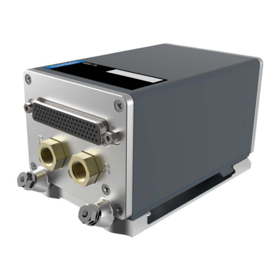
Figure 1-1. GSU 75 Unit View (in Rack)
Equipment Description
Section 1 GENERAL DESCRIPTION
Interface Summary
Technical Specifications
Table 1-1 GSU 75 with 117-00608-00 Rack
Table 1-2 Physical Characteristics GMU 44 (011-00870-00, 011-00870-10)
Table 1-4 General Specifications
Table 1-5 Power Requirements
Certification
Table 1-7 TSO Authorizations for GSU 75 (011-03094-X0)
Table 1-8 TSO Deviations for GSU 75 (011-03094-X0)
Operating Instructions
Reference Documentation
Table 1-10 Referenced Publications
Section 2 INSTALLATION OVERVIEW
Section 2 INSTALLATION OVERVIEW
Introduction
Installation Materials
Table 2-1 GSU 75 Part Numbers
Table 2-2 GMU 44 Part Numbers
Table 2-3 GTP 59 Part Numbers
Equipment Available
Table 2-4 GSU 75 Accessories
Table 2-5 GMU 44 Accessories
Additional Equipment Required
Cabling and Wiring
Electrical Bonding
Section 2 INSTALLATION OVERVIEW
Pneumatic Plumbing
Cooling Air
GTP 59 Icing
Figure 2-1 GSU 75 Air Hose Fitting Locations
Installation Approval Considerations for Pressurized Aircraft
Mounting Requirements
Figure 2-2 GSU 75 with Mounting Rack
Table 2-8 Recommended Distance from Magnetic Disturbances
Section 3 INSTALLATION PROCEDURE
Section 3 INSTALLATION PROCEDURE
Unpacking Unit
Wiring Harness Installation
Table 3-1 GSU 75 Pin Contact Part Numbers
Table 3-2 GMU 44 Pin Contact Part Number
Table 3-4 GMU 44 Recommended Crimp Tools
Table 3-3 GSU 75 Recommended Crimp Tools
Backshell Assembly and Installation
GSU 75/GMU 44 Interconnect Harness Fabrication Instructions
GSU 75/GTP 59 Interconnect Harness Fabrication Instructions
Table 3-5 Contents of GTP 59 Installation Kit (011-00978-00 )
Table 3-6 Parts Needed for GTP 59 to GSU 75 Installation (See Figure 3-2)
Section 3 INSTALLATION PROCEDURE
Figure 3-1 Insulation to Pin/Socket Clearance
Figure 3-2 GTP 59 Sensor - GSU 75 Interconnect Harness
Figure 3-3 GTP 59 Outline and Installation Drawing
Pneumatic Connections
Figure 3-4 GSU 75 Air Hose Fitting Locations
Mounting Instructions
Figure 3-5 GSU 75 Mounting
Post Installation Configuration and Checkout
Continued Airworthiness
Section 4 SYSTEM INTERCONNECTS
Section 4 SYSTEM INTERCONNECTS
Pin Function List
Table 4-1 J751 Connector
Section 4 SYSTEM INTERCONNECTS
Figure 4-2 Pigtail Connector J441
Table 4-2 J441 Pin Assignments
Power Functions
Table 4-3 GSU 75 Aircraft Power
Table 4-4 GMU 44 Input Power
Table 4-5 GSU 75 Magnetometer Power
Data Interfaces
Table 4-6 GSU 75 ARINC-429
Table 4-7 GSU 75 Configuration Module
Table 4-8 GSU 75 RS-232 I/O
Table 4-9 GMU 44 RS-232 I/O
Table
GSU 75 Discrete Inputs
Table 4-10 GSU 75 RS-422 I/O
Table 4-12 GSU 75 Discrete Inputs
GSU 75 OAT (Outside Air Temperature) Probe
GSU 75 PPS (Pulse Per Second) Inputs
Table 4-13 GSU 75 OAT Probe I/O
Table 4-14 GSU 75 PPS Inputs
Paragraph
GSU 75 ARINC 429 System ID Connections
GSU 75 System ID Inputs
Table 4-15. GSU 75 ARINC 429 System ID Connections
Table 4-16 GSU 75 System ID Inputs
Procedure5-1
Section 5 POST INSTALLATION, CONFIGURATION, and CHECKOUT
Procedure 5-1
Section 5 POST INSTALLATION, CONFIGURATION, and CHECKOUT PROCEDURE
Function Selector Switches and Display
Post-Installation Calibration Procedures
Table 5-1 Post-Installation Calibration Procedure Summary
Calibration Procedure A-1: Pitch/Roll Offset Compensation by Aircraft Leveling
Calibration Procedure A-2: Zero Pitch/Roll Offsets by Manual Entry
Procedure5-1
Section 5 POST INSTALLATION, CONFIGURATION, and CHECKOUT
Calibration Procedure B: Magnetometer Calibration
Figure 5-1. Fixed-Wing and Helicopter Position Examples
Calibration Procedure C: Heading Offset Compensation
Calibration Procedure D: Engine Run-Up Vibration Test
Calibration Procedure E: Magnetometer Interference Test
Table 5-2 Fixed-Wing Aircraft Magnetometer Interference Test Sequence Example
Table 5-3 Helicopter Magnetometer Interference Test Sequence Example
Site Evaluation of Magnetic Disturbances for Magnetometer Calibration Procedure
Appendix A ASSEMBLY and INSTALLATION DRAWINGS
Appendix A ASSEMBLY and INSTALLATION DRAWINGS
Figure A-1 GSU 75 Outline Drawing
Figure A-2 GSU 75 Installation Drawing
Figure A-3 GMU 44 (-00) Mounting Rack
Figure A-4 GMU 44 (-10 and -20) Mounting Rack
Figure A-5 GMU 44 (-00 and -10) Top Mounted Installation
Figure A-6 GMU 44 (-00 and -10) Bottom Mounted Installation
Figure A-7 GMU 44 (-20) Top Mounted Installation
Figure A-8 GMU 44 (-20) Bottom Mounted Installation
Figure A-9 GMU 44 Connector Assembly
Figure A-10 GMU 44 Minimum Recommended Installation Clearance
Appendix B INTERCONNECT DRAWING
Appendix B INTERCONNECT DRAWING
Figure B-1 GSU 75 Example Interconnect
Advertisement
Quick Links
1
Introduction
2
Section 1 General Description
3
Equipment Description
4
Technical Specifications
Download this manual
GSU 75 ADAHRS
Installation Manual
190-01639-00
May, 2017
Revision 6
340095
The document reference is online, please check the correspondence between the online documentation and the printed version.
Table of
Contents
Previous
Page
Next
Page
1
2
3
4
5
Advertisement
Table of Contents
Need help?
Do you have a question about the GSU 75 Series and is the answer not in the manual?
Ask a question
Questions and answers
Related Manuals for Garmin GSU 75 Series
Avionics Display Garmin G1000 Pilot's Manual
Integrated flight deck for the piper pa-32 saratoga series (482 pages)
GPS Garmin GDU 370 Installation Manual
Garmin gps receiver installation manual (188 pages)
GPS Garmin G300 Installation Manual
Pilot gps (120 pages)
GPS Garmin GRS 77 Installation Manual
(64 pages)
Avionics Display Garmin GSU 25 Owner's Manual
(17 pages)
Avionics Display Garmin GSU 75H Installation Manual
Adahrs (73 pages)
Avionics Display Garmin GSU 75B Installation Manual
Adahrs (73 pages)
Avionics Display Garmin G1000 Pilot's Manual
Primary flight display for cessna nav iii (53 pages)
Avionics Display garmin G1000 Reference Manual
Integrated flight deck (137 pages)
Avionics Display Garmin G1000 Manual Supplement
Integrated avionics system (65 pages)
Avionics Display Garmin Cessna Caravan G1000 Cockpit Reference Manual
Integrated flight deck for the cessna caravan (110 pages)
Avionics Display Garmin G1000 System Maintenance Manual
Installed in the hawker beechcraft 300/b300 series king air (302 pages)
Avionics Display Garmin G1000 Reference Manual
Cessna nav iii (176 pages)
Avionics Display Garmin G3X Quick Reference Manual
Multi function display (68 pages)
Avionics Display Garmin G3X Pilot's Manual
(470 pages)
Avionics Display Garmin G1000 NAV III Line Maintenance Manual
(248 pages)
This manual is also suitable for:
Gsu 75
Gsu 75h
Gsu 75b
Gmu44
011-03094-00
011-03094-20
...
Show all
011-03094-40
011-00870-00
011-00870-10
011-00870-20
010-01127-00
010-01127-20
010-01127-40
010-00296-00
010-00296-10
010-00296-20
Table of Contents
Save PDF
Print
Rename the bookmark
Delete bookmark?
Delete from my manuals?
Login
Sign In
OR
Sign in with Facebook
Sign in with Google
Upload manual
Upload from disk
Upload from URL


Need help?
Do you have a question about the GSU 75 Series and is the answer not in the manual?
Questions and answers