Garmin GIA 63 Installation Manual
Hide thumbs
Also See for GIA 63:
- Installation manual (94 pages) ,
- Installation manual (88 pages) ,
- Installation manual (108 pages)
Table of Contents
Advertisement
Advertisement
Table of Contents

Related Manuals for Garmin GIA 63


Summary of Contents for Garmin GIA 63
- Page 1 GIA 63 Installation Manual 190-00303-05 December, 2012 Revision Y...
- Page 2 Except as expressly provided herein, no part of this manual may be reproduced, copied, transmitted, disseminated, downloaded or stored in any storage medium, for any purpose without the express prior written consent of Garmin. Garmin hereby grants permis- sion to download a single copy of this manual and of any revision to this manual onto a hard drive or other electronic storage medium...
- Page 3 2-1 – 2-18 Section 3 3-1 – 3-8 Section 4 4-1 – 4-40 Section 5 5-1 – 5-6 Appendix A A-1 – A-4 Appendix B B-1 – B-6 Appendix C C-1 – C-7 190-00303-05 GIA 63 Installation Manual Rev. Y Page i...
- Page 4 NOTE Notes are used to expand and explain the preceding step and provide further understanding of the reason for the particular operation. GIA 63 Installation Manual 190-00303-05 Page ii Rev. Y...
-
Page 5: Limited Warranty
(iv) damage caused by service performed by anyone who is not an authorized service provider of Garmin; or (v) damage to a product that has been modified or altered without the written permission of Garmin. -
Page 6: Table Of Contents
2.3 Rack Considerations ...................... 2-10 2.4 Cabling and Wiring ....................... 2-11 2.5 Cooling Air ........................2-11 2.6 GIA 63 Minimum Installation Requirements ..............2-12 2.7 GIA 63W and GIA 63H Minimum Installation Requirements ........2-13 2.8 Mounting Requirements ....................2-14 3 INSTALLATION PROCEDURE ..............3-1... - Page 7 Appendix A GIA 63 MAIN BOOT BLOCK UPLOADING INSTRUCTIONS ..A-1 A.1 Introduction........................A-1 A.2 Determining Current Boot Block................... A-1 A.3 Loading Boot Block Version 4.01 ................. A-2 A.4 Loading GIA Main Software (only if GIA main software was cancelled in Section A.2)A-3 Appendix B OUTLINE AND INSTALLATION DRAWINGS........B-1...
- Page 8 GIA 63 HARDWARE MOD LEVEL HISTORY The following table identifies hardware modification (Mod) Levels for the GIA 63. Mod Levels are listed with the associated service bulletin number, service bulletin date, and the purpose of the modification. The table is current at the time of publication of this manual (see date on front cover) and is subject to change without notice.
- Page 9 The table is current at the time of publication of this manual (see date on front cover) and is subject to change without notice. Authorized Garmin Sales and Service Centers are encouraged to access the most up-to-date bulletin and advisory information on the Garmin Dealer Resource web site at www.garmin.com using their Garmin-provided user name and password.
- Page 10 This page intentionally left blank GIA 63 Installation Manual 190-00303-05 Page viii Rev. Y...
-
Page 11: General Description
This manual is intended to provide mechanical and electrical information for use in the planning and design of an installation of the GIA 63(X) into an aircraft. This manual is not a substitute for an approved airframe-specific maintenance manual, installation design drawing, or complete installation data package. -
Page 12: Interface Summary
1.3 Interface Summary 1.3.1 Primary Interfaces The GIA 63(X) is designed as an open architecture system that provides the following interfaces: • 1 dedicated Ethernet High-Speed Data Bus (HSDB) input/output channel • 2 Controller Area Network (CAN) I/O channels •... -
Page 13: Technical Specifications
1.4.1 Environmental Qualification Form It is the responsibility of the installing agency to obtain the latest revision of the GIA 63(X) Environmental Qualification Form. This form is available directly from Garmin under the following part number: GIA 63 Environmental Qualification Form, Garmin part number 005-00148-02 GIA 63W Environmental Qualification Form, Garmin part number 005-00235-00 The GIA 63H and the GIA 63W are included in the 005-00235-00. - Page 14 1.4.3 General Specifications For detailed specifications, see the Environmental Qualification Form. Table 1-2. GIA 63(X) General Specifications Characteristic Specification -40°C to +65°C. For more details see Environmental Operating Temperature Range Qualification Form Humidity 95% non-condensing Altitude Range -1,500 ft to 50,000 ft...
- Page 15 1.4.4 GPS Specification (GIA 63 only) Table 1-3. GIA 63 GPS Specifications Characteristic Specification Search-the-Sky (without almanac, without initial position or time): 5 minutes AutoLocate™ (with almanac, without initial position or time): 5 minutes Acquisition Times Cold Start (position known to 300 nm, time known to 10 minutes,...
- Page 16 *When utilizing the configurable microphone gain adjustments, the modulation capability specification can be met with a 70 mVrms to 3.0 Vrms analog microphone input signal applied to the transmitter. When a digital audio microphone signal is provided by a compatible Garmin audio panel, the modulation capability specification can be met with a minimum 70 mVrms microphone input signal applied to the audio panel.
- Page 17 1.4.7 VOR Specifications Table 1-6. GIA 63(X) VOR Specifications Characteristic Specification Receiver Audio At -103.5 dBm (S+N)/N shall not be less than 6 dB Sensitivity At –103.5 dBm deviation output shall not be less than 60% of standard Course Deviation...
-
Page 18: Loc Specifications
1.4.8 LOC Specifications Table 1-7. GIA 63(X) LOC Specifications Characteristic Specification Receiver Audio At -103.5 dBm (S+N)/N shall not be less than 6 dB Sensitivity Course Deviation At –103.5 dBm, deviation output shall not be less than 60% of standard... -
Page 19: Glideslope Specifications
1.4.9 Glideslope Specifications Table 1-8. GIA 63(X) Glideslope Specifications Characteristic Specification At –93 dBm, deviation output shall not be less than 60% of standard Sensitivity deflection when glideslope deviation test signal is applied Centering Accuracy 0 ± .0091 ddm or 0 ± 7.8 mV... - Page 20 Table 1-9. GIA 63(X) Power Specifications Characteristic Specification Superflag Power Power depends upon loads present on Superflag output pins Requirements for P605 (see Sections 4.7.2.1 and 4.10.7) (Main 2 Connector) Power Requirements 1.0 A max @ 27.5 Vdc (Without Superflags Active) for P605 2.0 A max @ 13.75 Vdc (Without Superflags Active)
-
Page 21: License Requirements
If an aircraft license is required, make application for a license on FCC form 404, application for Aircraft Radio Station License. The FCC also has a fax-on-demand service to provide forms by fax. The GIA 63(X) owner accepts all responsibility for obtaining the proper licensing before using the transmitter. -
Page 22: Certification
Approval for Precession RNAV Operations in Designated European Airspace 7.1 Required Functions. The GIA 63(X) with main software version 7.00 or later and GPS software version 5.0 or later have been shown to comply with AC 20-165 Appendix 2 and AC 20-138C Appendix 4 and are eligible for use as an ADS-B Out Position Source meeting the requirements of 14 CFR 91.227 when installed in accordance... - Page 23 1.6.1 GIA 63 TSO/ETSO Compliance Table 1-11. GIA 63 TSO/ETSO Compliance Applicable LRU SW Part Applicable CLD Function TSO/ETSO Category Numbers Part Numbers 006-C0046-() 006-B0190-() 006-C0044-() except TSO-C9c Automatic Pilots 006-C0047-() 006-B0190-00 ETSO-C9c through 006-C0039-01 006-B0190-19 006-C0046-() 006-B0190-() 006-C0044-() Glideslope...
- Page 24 Table 1-11. GIA 63 TSO/ETSO Compliance Applicable LRU SW Part Applicable CLD Function TSO/ETSO Category Numbers Part Numbers 006-C0046-() Ground Proximity 006-B0190-() 006-C0044-() Warning – Glide except TSO-C92c 006-C0047-() Slope Deviation 006-B0190-00 Alerting through 006-C0039-01 Equipment 006-B0190-29 006-C0046-() 006-B0190-() 006-C0044-()
- Page 25 3. Garmin was granted a deviation from TSO-C9c subpart A (c), which requires marking the weight of the unit on the unit. Garmin will provide this information in the installation manual in lieu of marking on the serial tag. Garmin does not currently list the weight on other avionics units.
- Page 26 1. Garmin was granted a deviation from TSO-C92c to use DO-160D Change 3 instead of DO-160C. 2. Garmin was granted a deviation from TSO-C92c to not include the version and levels of software or the modification status of hardware in the appliance number.
- Page 27 006-B0544-1() 006-C0072-0() through 006-C0085-0() 006-B0544-4() 006-B0082-0() and all TSO-C36e except Localizer 006-C0039-0() Class A 006-B0544-B() Receiver ETSO-2C36f 006-B0082-00 except except through 006-C0039-00 006-B0544-BA 006-B0082-02 through through 006-C0039-02 006-B0544-BB 006-C0053-0() except 006-C0053-00 190-00303-05 GIA 63 Installation Manual Rev. Y Page 1-17...
- Page 28 Equipment ETSO-C52b 006-B0544-B() except 006-C0039-0() 006-B0544-BA except through 006-C0039-00 006-B0544-BB through 006-C0039-02 006-B0544-4() 006-C0084-0() and all except 006-B0544-B() 006-C0084-00 Stall Warning TSO-C54 Type II except 006-C0072-0() Instruments 006-B0544-BA through 006-C0085-0() 006-B0544-BB GIA 63 Installation Manual 190-00303-05 Page 1-18 Rev. Y...
- Page 29 006-C0039-00 006-B0544-BB through 006-C0039-02 TAWS 006-C0084-0() except 006-B0544-3() 006-C0084-00 through 006-C0072-0() 006-B0544-4() TSO-C151b Class A and all 006-C0085-0() ETSO-C151b and B 006-B0544-B() except 006-C0039-0() 006-B0544-BA except through 006-C0039-00 006-B0544-BB through 006-C0039-02 190-00303-05 GIA 63 Installation Manual Rev. Y Page 1-19...
- Page 30 Equipment except through 006-C0039-0() ETSO-2C38e (receiver) 006-B0544-BA 006-B0081-04 except through 006-C0039-00 006-B0544-BB through 006-C0039-02 *GIA63W ARINC output labels 310 and 311 are not to be used as navigation data per RTCA/DO-229c. GIA 63 Installation Manual 190-00303-05 Page 1-20 Rev. Y...
- Page 31 3. Garmin was granted a deviation from TSO-C9c subpart A (c), which requires marking the weight of the unit on the unit. Garmin will provide this information in the installation manual in lieu of marking on the serial tag. Garmin does not currently list the weight on other avionics units.
- Page 32 1. Garmin was granted a deviation from TSO-C92c to use DO-160E instead of DO-160C. 2. Garmin was granted a deviation from TSO-C92c to not include the version and levels of software or the modification status of hardware in the appliance number.
- Page 33 3. Garmin was granted a deviation to TSO-C169, paragraph 4.e requirement to mark (DEV) after the TSO number on the equipment. Garmin will mark as follows, as TSOC169 is not the primary TSO and the Install Manual contains all of the TSO-C169 information including deviations.
- Page 34 006-B0544-BD 006-B0544-3() 006-C0084-0() through except 006-B0544-4() 006-C0084-00 except 006-C0072-0() 006-B0544-30 006-C0085-0() TSO-C36e through 006-B0082-1() Localizer Class A Receiver ETSO-2C36f 006-B0544-34 except and all 006-B0082-10 006-B0544-B() 006-C0124-0() except 006-B0544-BA through 006-B0544-BD GIA 63 Installation Manual 190-00303-05 Page 1-24 Rev. Y...
- Page 35 Equipment ETSO-C52b 006-B0544-34 and all 006-B0544-B() 006-C0085-0() except 006-B0544-BA through 006-B0544-BD 006-B0544-4() 006-C0084-0() and all except 006-B0544-B() 006-C0084-00 Stall Warning TSO-C54 Type II Instruments except 006-C0072-0() 006-B0544-BA through 006-C0085-0() 006-B0544-BD 190-00303-05 GIA 63 Installation Manual Rev. Y Page 1-25...
- Page 36 Part Numbers 006-B0544-3() 006-C0084-0() through except 006-B0544-4() 006-C0084-00 except 006-C0072-0() Ground Proximity 006-B0544-30 Warning – Glide TSO-C92c through Slope Deviation ETSO-C92c 006-B0544-34 Alerting and all Equipment 006-B0544-B() 006-C0085-0() except 006-B0544-BA through 006-B0544-BD GIA 63 Installation Manual 190-00303-05 Page 1-26 Rev. Y...
- Page 37 006-B0544-34 & Equipment and all ETSO-2C38e (receiver) 006-B0544-B() 006-C0085-0() except 006-B0544-BA through 006-B0544-BD *GIA 63W ARINC output labels 310 and 311 are not to be used as navigation data per RTCA/DO-229c. 190-00303-05 GIA 63 Installation Manual Rev. Y Page 1-27...
- Page 38 006-B0544-BD 006-B0544-3() 006-C0084-0() through except 006-B0544-4() 006-C0084-00 except 006-C0072-0() 006-B0544-30 006-C0085-0() TSO-C36e through 006-B0082-1() Localizer Class A Receiver ETSO-2C36f 006-B0544-35 except and all 006-B0082-10 006-B0544-B() 006-C0124-0() except 006-B0544-BA through 006-B0544-BD GIA 63 Installation Manual 190-00303-05 Page 1-28 Rev. Y...
- Page 39 Equipment ETSO-C52b 006-B0544-35 and all 006-B0544-B() 006-C0085-0() except 006-B0544-BA through 006-B0544-BD 006-B0544-4() 006-C0084-0() and all except 006-B0544-B() 006-C0084-00 Stall Warning TSO-C54 Type II Instruments except 006-C0072-0() 006-B0544-BA through 006-C0085-0() 006-B0544-BD 190-00303-05 GIA 63 Installation Manual Rev. Y Page 1-29...
- Page 40 System* 006-B0544-BA through 006-B0544-BD 006-B0544-3() 006-C0084-0() through except 006-B0544-4() 006-C0084-00 except 006-C0072-0() 006-B0544-30 TSO-C151b Class A through TAWS ETSO-C151b and B 006-B0544-35 and all 006-B0544-B() 006-C0085-0() except 006-B0544-BA through 006-B0544-BD GIA 63 Installation Manual 190-00303-05 Page 1-30 Rev. Y...
- Page 41 006-B0544-35 & Equipment and all ETSO-2C38e (receiver) 006-B0544-B() 006-C0085-0() except 006-B0544-BA through 006-B0544-BD *GIA 63H ARINC output labels 310 and 311 are not to be used as navigation data per RTCA/DO-229c. 190-00303-05 GIA 63 Installation Manual Rev. Y Page 1-31...
- Page 42 3. Garmin was granted a deviation from TSO-C9c subpart A (c), which requires marking the weight of the unit on the unit. Garmin will provide this information in the installation manual in lieu of marking on the serial tag. Garmin does not currently list the weight on other avionics units.
- Page 43 10 second reacquisition time. TSO-C151b 1. Garmin was granted a deviation from TSO-C151b to use DO-160E instead of DO-160D. 2. Garmin was granted a deviation from TSO-C151b 4.a. to mark the unit with the serial number instead of the date of manufacture. ETSO-C151b 1.
- Page 44 006-B0544-B() 006-C0084-00 VOR Receiver TSO-C40c except except 006-C0072-0() 006-B0082-10 006-B0544-BA 006-C0085-0() through 006-C0124-0() 006-B0544-BD 006-B0544-4() 006-C0084-0() and all except Flight Director 006-B0544-B() 006-C0084-00 TSO-C52b Equipment except 006-C0072-0() 006-B0544-BA through 006-C0085-0() 006-B0544-BD GIA 63 Installation Manual 190-00303-05 Page 1-34 Rev. Y...
- Page 45 Type II Instruments except 006-C0072-0() 006-B0544-BA through 006-C0085-0() 006-B0544-BD 006-B0544-4() 006-C0084-0() Ground Proximity and all except Warning – Glide 006-B0544-B() 006-C0084-00 Slope Deviation TSO-C92c except 006-C0072-0() Alerting 006-B0544-BA Equipment through 006-C0085-0() 006-B0544-BD 190-00303-05 GIA 63 Installation Manual Rev. Y Page 1-35...
- Page 46 Transceiver except 006-C0072-0() Equipment 006-B0544-BA (receiver) 006-B0081-11 through 006-C0085-0() 006-B0544-BD *GIA 63W with Enhanced COM ARINC output labels 310 and 311 are not to be used as navigation data per RTCA/DO-229D GIA 63 Installation Manual 190-00303-05 Page 1-36 Rev. Y...
- Page 47 3. Garmin was granted a deviation from TSO-C9c subpart A (c), which requires marking the weight of the unit on the unit. Garmin will provide this information in the installation manual in lieu of marking on the serial tag. Garmin does not currently list the weight on other avionics units.
- Page 48 DO-224B table 3-7. 3. Garmin was granted a deviation from RTCA/DO-224B table 3-18 to allow bit 7 to be set as defined in paragraph 7.9 of ARINC 631-5 so that the air/ground bit can be utilized for the purpose of inform- ing the avionics whether the ground or air Frequency Support List should be used.
- Page 49 Deviation TSO-C169a 1. Garmin was granted a deviation from TSO-C169a paragraph 4.a.2 to allow the unit to be perma- nently and legibly marked with a serial number and not the date of manufacture. 2. Garmin was granted a deviation from RTCA/DO-186B sections 2.4.8 and 2.5.8 to interpret Fluids Susceptibility (RTCA/DO-160E, Section 11.0) testing as "When Required”...
- Page 50 WAAS NOTAMs (or their absence) and generic prediction tools do not provide an acceptable indication of the availability for the GIA 63W or GIA 63H equipment. 4. When flight planning an LNAV/VNAV or LPV approach, operators should use the Garmin Prediction Program 006-A0154-01 with the <insert installed antenna part number> antenna selection in addition to any NOTAMs issued for the approach.
- Page 51 RFMS, and/or POH provided the system is installed in accordance with [AC 20-138C] and is comprised of [two or more] [TSO-C145a Class 3 or TSO-C145c Class 3] approved Garmin GIA 63Ws or GIA 63Hs, [two or more] [TSO-C146a Class 3 or TSO-C146c Class 3] approved Garmin GDU 1XXX Display Units, Garmin-approved GPS/SBAS antennas (refer to Section 2.1.3.2), and GPS software version [3.2 or later...
- Page 52 No 10 (JAA TGL-10 Rev 1). The GNSS navigation system has [two or more] [ETSO-C145 Class 3 or ETSO-C145c Class 3 / TSO-C145a Class 3 or TSO-C145c Class 3] approved Garmin GIA 63Ws or GIA 63Hs, and [two or more] [ETSO-146 Class 3 or ETSO-C146c Class 3 / TSO-C146a Class 3 or TSO-C146c Class 3] approved Garmin GDU 1XXX Display Units.
- Page 53 For flight planning purposes, operations where the route requires Class II navigation the aircraft’s operator or flight crew must use the Garmin WFDE Prediction program to demonstrate that there are no outages on the specified route that would prevent the Garmin GNSS navigation system from providing GPS Class II navigation in oceanic and remote areas of operation that requires (RNP-10 or RNP-4) capability.
- Page 54 The navigation equipment required to join and fly an instrument approach procedure is indicated by the title of the procedure and notes on the IAP chart. Use of the Garmin GPS/SBAS receivers to provide navigation guidance during the final approach segment of an ILS, LOC, LOC-BC, LDA, SDF, MLS or any other type of approach not approved for “or GPS”...
- Page 55 1.6.11 Other Regulatory Criteria (GIA 63) RTCA/DO-178B Level B, C, D (Software) EUROCAE ED 12B (Software) RTCA/DO-160D (Environmental Conditions) EUROCAE ED 14D (Environmental Conditions) RTCA/DO-161A (Airborne Ground Proximity Warning Equipment) RTCA/DO-208 Class A1 (GPS) RTCA/DO-186a Class 3 and 5 (VHF Com Transmitter)
- Page 56 RTCA/DO-186b Class 3 and 5 (VHF Com Transmitter) RTCA/DO-186b Class C and E (VHF Com Receiver) ICAO Annex 10 Volume III, EUROCAE ED-23C (VHF Com Transceiver) RTCA/DO-281a (VDL Mode 2) RTCA/DO-224b (VHF Digital Data) GIA 63 Installation Manual 190-00303-05 Page 1-46 Rev. Y...
-
Page 57: Reference Documents
1.7 Reference Documents The following publications are sources of additional information for installing the GIA 63(X). Before installing the GIA 63(X), the technician should read all relevant referenced materials along with this manual. Table 1-20. GIA 63(X) Reference Documents Part Number... - Page 58 This page intentionally left blank GIA 63 Installation Manual 190-00303-05 Page 1-48 Rev. Y...
-
Page 59: Installation Overview
This section provides hardware equipment information for installing the GIA 63(X), related hardware, and antennas. Installation of the GIA 63(X) should follow the aircraft TC or STC requirements. Cabling is fabricated by the installing agency to fit each particular aircraft. The guidance of FAA advisory circulars AC 43.13-1B and AC 43.13-2B, where applicable, may be found useful for making retro-fit installations... - Page 60 2.1.2 Required Accessories Each of the following accessories is provided separately from the GIA 63(X). Either rack (modular, standalone, or helicopter) and reminder of the accessories are required for installation. Table 2-2. Required Accessories Item Garmin P/N GIA 63(W) Modular Install Rack...
- Page 61 In addition, TSO-C144 antennas can also meet TSO-C129a requirements for the GIA 63 (non-WAAS) if their additional gain (which is about 16dB at 1.5 GHz for antennas produced by Garmin) is offset by added attenuation in-line with the GIA 63 (non-WAAS). If an in-line attenuator is used, it must pass DC current (40 mA max at 4.6 VDC) which is provided from the GPS receiver to the antenna pre-amplifier.
- Page 62 ARINC 743 Comant Footprint 428-410 CI 428-410 FIS/WAAS Antenna [6][8] Comant 2728-200 WAAS and CI 2728-200 Screw Antenna Mount, [6][8] Comant Teardrop Comant Footprint 2728-410 FIS/WAAS CI 2728-410 /COM Antenna [6][8] GIA 63 Installation Manual 190-00303-05 Page 2-4 Rev. Y...
- Page 63 [5] The WAAS GPS antenna connector (and XM antenna connector where applicable) is TNC type. The VHF COM antenna connector is BNC type. [6] Not approved for use with the GIA 63 (non-WAAS) since max DC current specification exceeds 40 mA.
-
Page 64: Installation Considerations
2.2 Installation Considerations The GIA 63(X) interfaces with the G1000 system and with various avionics equipment. Fabrication of a wiring harness is required. Sound mechanical and electrical methods and practices are required for installation of the GIA 63(X). 2.2.1 Antenna Considerations... - Page 65 NOTE The separation requirement does not apply to GPS and COM combination antennas, provided the antenna model is TSO authorized and has been tested to meet Garmin’s minimum performance standards. The separating requirement includes the combination with an XM antenna element as well.
- Page 66 Figure 2-1 shows the recommended placement of antennas. Figure 2-1. GPS Antenna Considerations GIA 63 Installation Manual 190-00303-05 Page 2-8 Rev. Y...
-
Page 67: Com Antenna Location
The antenna should be mounted a minimum of six feet from any DME or other COM antennas, four feet from any ADF sense antennas, three feet from the GIA 63(X) and its GPS antenna, and as far as practical from any ELT antennas. -
Page 68: Rack Considerations
2.3 Rack Considerations A location away from heating vents or other sources of heat generation is optimal. The GIA 63(W) can be mounted using the G1000 system rack. The unit may be mounted remotely if desired. The GIA 63H must be mounted in the Helicopter Rack. -
Page 69: Cabling And Wiring
A typical maximum cable length for the GPS antenna is 40 feet. The installer shall insure that the attenuation does not exceed 10 dB at 1.5 GHz for the GIA 63, and falls between 3 dB and 7 dB inclusive at 1.5 GHz for the GIA 63W or GIA 63H. -
Page 70: Gia 63 Minimum Installation Requirements
2.6 GIA 63 Minimum Installation Requirements Below is a list of required devices for TSO-C129a category A1 certification. Pressure Altitude Device This device delivers pressure altitude data to the GIA 63. This data comes from the Garmin GDC 74A Air Data Computer. Manual Course Device This device delivers the manual course select to the GIA 63, which is required for the VOR receiver, and optional for the GPS receiver. -
Page 71: Gia 63W And Gia 63H Minimum Installation Requirements
In addition it provides manual course selection to the GIA, which is required for the VOR receiver and optional for the GPS receiver. Qualified GPS Antenna Refer to Section 2.1.3.2 for a list of approved antennas. 190-00303-05 GIA 63 Installation Manual Rev. Y Page 2-13... -
Page 72: Mounting Requirements
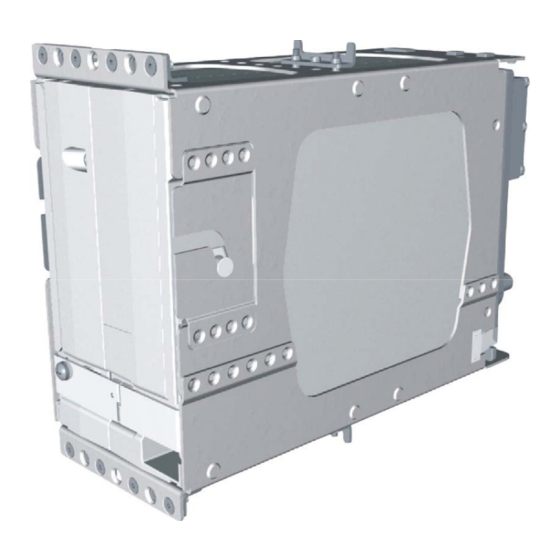
Modular Rack Considerations Figure 2-2 and Figure B-2 show the GIA 63(W) G1000 modular rack. The modular rack is fastened to the main system rack using the nutplate kit listed in Section 2.1.2. Refer to Figure B-2 for nutplate placement locations. - Page 73 #8-32 pan head screws (MS35206, AN526, or other approved fastener). It can also be mounted horizontally using four #6-32 100° counter-sunk flathead screws (MS24693, AN507R, or other approved fastener). Ensure that the GIA 63(W) chassis has a ground path to the airframe by having at least one mounting screw in contact with the airframe.
- Page 74 Figure 2-4. GIA 63H Standalone Rack GIA 63 Installation Manual 190-00303-05 Page 2-16 Rev. Y...
- Page 75 Figure 2-5. GIA 63(W) Standalone Rack, Suggested Mounting Locations 190-00303-05 GIA 63 Installation Manual Rev. Y Page 2-17...
- Page 76 This page intentionally left blank GIA 63 Installation Manual 190-00303-05 Page 2-18 Rev. Y...
-
Page 77: Installation Procedure
If the unit is damaged, notify the carrier and file a claim. To justify a claim, save the original shipping container and all packing materials. Do not return the unit to Garmin until the carrier has authorized the claim. -
Page 78: Wiring Harness Installation
615725 M81969/1-04 NOTES 1. Non-Garmin part numbers shown are not maintained by Garmin and consequently are subject to change without notice. 2. Extraction of 16 and 18 AWG contacts requires that the expanded wire barrel be cut off from the contact. -
Page 79: Antenna Installation
3. Contacts for the 78, 62, and 44 pin connectors must be crimped onto the individual wires of the aircraft wiring harness. Tables 3-1 and 3-2 list contact part numbers (for reference) and recommended crimp tools. 190-00303-05 GIA 63 Installation Manual Rev. Y Page 3-3... -
Page 80: Backshell Assembly
4. Assemble the NAV and Main rear plates into the GIA 63(W) unit rack. 5. Carefully slide the GIA 63(W) into the rack. Ensure that the orientation of the unit allows for the engagement of the locking stud in the channel on the rack. The unit can only be installed in one direction. -
Page 81: Post Installation Configuration & Checkout
3.7 Post Installation Configuration & Checkout All configuration and checkout procedures take place upon completion of the installation of the Garmin Integrated Flight Deck. The GDU serves as the graphics user interface to the installer configuring the system. For sample configuration and checkout procedures, refer to the G1000 Line Maintenance and Configuration Manual, Garmin part number 190-00303-04. -
Page 82: Continued Airworthiness
3.8 Continued Airworthiness Maintenance of the GIA 63(X) is “on condition” for all units installed in airframes that require power interrupt Category B (50mS). For airframes that require the GIA 63(X) to comply with RTCA/DO-160D or RTCA/DO-160E (as specified in applicable Environmental Qualification Form) power interrupt Category A (200mS), one of the following two actions must be taken to ensure backup time is adequate: •... - Page 83 Category A Long Term Power Interrupt Annual Inspection NOTE In order to comply with this procedure GIA 63 main software version must be 5.30 or later, GIA 63W main software version must be 5.21 or later, and GDU main software version must be 7.10 or later.
- Page 84 This page intentionally left blank GIA 63 Installation Manual 190-00303-05 Page 3-8 Rev. Y...
-
Page 85: System Interconnects
ON-SIDE COM MIC DIGITAL AUDIO IN SIGNAL GROUND COM REMOTE POWER OFF AIRCRAFT POWER 1 SPARE CROSS-SIDE COM MIC DIGITAL AUDIO IN (011-01105-2X/-3X/-4X ONLY) AIRCRAFT POWER 1 SPARE AIRCRAFT POWER 1 190-00303-05 GIA 63 Installation Manual Rev. Y Page 4-1... - Page 86 RESERVED RESERVED COM SECONDARY TX INTERLOCK* (011-01105-4X ONLY) RESERVED RESERVED RESERVED RESERVED RESERVED RESERVED RESERVED RESERVED POWER GROUND POWER GROUND *Indicates Active Low (Ground to activate) † Pin not currently supported GIA 63 Installation Manual 190-00303-05 Page 4-2 Rev. Y...
- Page 87 KING SERIAL DME CLOCK (011-00781-0X AND 011-01105-0X ONLY) KING SERIAL DME DATA (011-00781-0X AND 011-01105-0X ON LY) KING SERIAL RNAV REQUEST (011-00781-0X AND 011-01105-0X ONLY) KING SERIAL RNAV* MODE 011-00781-0X AND 011-01105-0X ONLY 190-00303-05 GIA 63 Installation Manual Rev. Y Page 4-3...
- Page 88 PARALLEL DME 100 KHZ-C DME COMMON PARALLEL DME 100 KHZ-D PARALLEL DME 50 KHZ RESERVED PARALLEL DME 1 MHZ-A PARALLEL DME 1 MHZ-B PARALLEL DME 1 MHZ-C RESERVED SIGNAL GROUND RESERVED SPARE SPARE GIA 63 Installation Manual 190-00303-05 Page 4-4 Rev. Y...
- Page 89 PARALLEL DME 1MHZ-E RESERVED SPARE GLIDESLOPE COMPOSITE OUT (011-01105-2X/-3X/-4X ONLY) VOR/LOC DIGITAL AUDIO OUT SIGNAL GROUND POWER GROUND POWER GROUND *Indicates Active Low (Ground to activate) † Pin not currently supported 190-00303-05 GIA 63 Installation Manual Rev. Y Page 4-5...
- Page 90 MAIN ARINC 429 IN 7 B MAIN ARINC 429 IN 8 A MAIN ARINC 429 IN 8 B CAN BUS 1 HI RESERVED CAN BUS 1 LO RS-485 1 A RS-485 1 B RS-485 2 A GIA 63 Installation Manual 190-00303-05 Page 4-6 Rev. Y...
- Page 91 SIGNAL GROUND MAIN RS-232 OUT 3 MAIN RS-232 IN 4 SIGNAL GROUND MAIN RS-232 OUT 4 MAIN RS-232 IN 5 SIGNAL GROUND MAIN RS-232 OUT 5 MAIN RS-232 IN 6 SIGNAL GROUND 190-00303-05 GIA 63 Installation Manual Rev. Y Page 4-7...
- Page 92 MAIN ARINC 429 OUT 2 A MAIN ARINC 429 OUT 3 B MAIN ARINC 429 OUT 3 A ETHERNET IN A ETHERNET IN B RESERVED *Indicates Active Low (Ground to activate) † Pin not currently supported GIA 63 Installation Manual 190-00303-05 Page 4-8 Rev. Y...
- Page 93 DISCRETE IN 17 DISCRETE IN* 7 DISCRETE IN* 8 DISCRETE IN* 9 DISCRETE IN* 10 DISCRETE IN* 11 GIA SYSTEM ID PROGRAM* 1 GIA SYSTEM ID PROGRAM* 2 DISCRETE IN* 12 ANNUNCIATE* 2 190-00303-05 GIA 63 Installation Manual Rev. Y Page 4-9...
- Page 94 ANNUNCIATE* 12 ANNUNCIATE* 13 ANNUNCIATE* 14 ANNUNCIATE* 15 ANNUNCIATE* 16 ANNUNCIATE* 17 ANNUNCIATE* 18 ANNUNCIATE* 19 ANNUNCIATE* 20 ANNUNCIATE* 21 *Indicates Active Low (Ground to activate) † Pin not currently supported GIA 63 Installation Manual 190-00303-05 Page 4-10 Rev. Y...
- Page 95 MAIN LATERAL DEVIATION +LEFT MAIN LATERAL DEVIATION +RIGHT (MAIN COMMON) MAIN LATERAL +FLAG MAIN LATERAL –FLAG (MAIN COMMON) SPARE SPARE MAIN VERTICAL DEVIATION +UP MAIN VERTICAL DEVIATION +DOWN (MAIN COMMON) MAIN VERTICAL +FLAG 190-00303-05 GIA 63 Installation Manual Rev. Y Page 4-11...
- Page 96 SIGNAL GROUND DISCRETE IN* 11A DISCRETE IN 21A DISCRETE IN 22A DISCRETE IN* 12A DISCRETE IN* 13A DISCRETE IN* 14A DISCRETE IN* 15A OUTER MARKER LAMP IN MIDDLE MARKER LAMP IN GIA 63 Installation Manual 190-00303-05 Page 4-12 Rev. Y...
- Page 97 DISCRETE OUT* 4A ANNUNCIATE* 1A ANNUNCIATE* 2A DISCRETE IN* 17A DISCRETE IN 24A SUPERFLAG 2A POWER GROUND SUPERFLAG 3A POWER GROUND *Indicates Active Low (Ground to activate) † Pin not currently supported 190-00303-05 GIA 63 Installation Manual Rev. Y Page 4-13...
- Page 98 HEADING X† HEADING Y† HEADING Z (GROUND)† SIGNAL GROUND PITCH ATTITUDE X† PITCH ATTITUDE Y† PITCH ATTITUDE Z (GROUND)† ROLL ATTITUDE X† ROLL ATTITUDE Y† ROLL ATTITUDE Z (GROUND)† SIGNAL GROUND SPARE GIA 63 Installation Manual 190-00303-05 Page 4-14 Rev. Y...
- Page 99 COURSE DATUM LO (GROUND) SIGNAL GROUND 26 VAC DIRECTIONAL GYRO REF HI† 26 VAC DIRECTIONAL GYRO REF LO† REMOTE ANNUNCIATE CLOCK REMOTE ANNUNCIATE DATA REMOTE ANNUNCIATE SYNC MAIN OBI CLOCK† MAIN OBI DATA† 190-00303-05 GIA 63 Installation Manual Rev. Y Page 4-15...
- Page 100 DISCRETE OUT* 5B DISCRETE OUT* 6B DISCRETE OUT* 7B DISCRETE OUT* 8B DISCRETE OUT* 9B RESERVED DISCRETE OUT* 10B RESERVED *Indicates Active Low (Ground to activate) † Pin not currently supported GIA 63 Installation Manual 190-00303-05 Page 4-16 Rev. Y...
-
Page 101: Power And Antennas
P601 are internally connected to form AIRCRAFT POWER 2. AIRCRAFT POWER 1 and AIRCRAFT POWER 2 are “diode ORed” to provide power redundancy. The same applies to pins 29/31 and pins 33/35 of P605. 190-00303-05 GIA 63 Installation Manual Rev. Y Page 4-17... - Page 102 Source current is internally limited to 1.5 mA max for a 10-33VDC input 4.2.1.3 Antennas Table 4-9. Antennas Pin Name Connector GPS ANTENNA P611 COM ANTENNA P612 VOR/LOC ANTENNA P613 GLIDESLOPE ANTENNA P614 GIA 63 Installation Manual 190-00303-05 Page 4-18 Rev. Y...
-
Page 103: Gia System Id Program
4.3 GIA System ID Program The GIA 63(X) utilizes a hard strapping method to assign a unit ID to a unit. Unit ID’s identify a unit as a #1, #2, #3, or #4 GIA. Table 4-10. GIA System ID Program... - Page 104 RS-485 4 B P603 The GIA 63(X) contains a total of 5 channels of RS-485 serial data communications. Any two of these channels can also be configured as one RS-422 channel to allow for system flexibility. These data busses conform to EIA standard RS-485, or RS-422, depending on which mode they are currently operating in.
- Page 105 VOR/ILS ARINC 429 IN B P602 VOR/ILS ARINC 429 IN A P602 The MAIN and VOR/ILS ARINC 429 outputs conform to ARINC 429 electrical specifications when loaded with up to 5 standard ARINC 429 receivers. 190-00303-05 GIA 63 Installation Manual Rev. Y Page 4-21...
- Page 106 ETHERNET IN B P603 This Ethernet based high speed data bus (HSDB) provides communications capability with the GDU. HSDB meets the hardware aspects of IEEE standard 802.3 for 10 base T Ethernet communications. GIA 63 Installation Manual 190-00303-05 Page 4-22 Rev. Y...
-
Page 107: Discrete I/O
Leakage current in the INACTIVE state is typically ≤ 250 uA to ground ACTIVE: Vout ≤ 0.5VDC with ≤ 500 mA sink current Sink current must be externally limited to 500 mA max 190-00303-05 GIA 63 Installation Manual Rev. Y Page 4-23... -
Page 108: Com/Vor/Ils/Digital Audio
121.50 MHz. Once the emergency frequency is activated through COM REMOTE TRANSFER*, the GIA 63(X) ignores inputs from the front panel controls for COM selections only. The pilot may exit this independent mode—restoring COM selection control to the front panel knobs and buttons—by momentarily depressing the COM REMOTE TRANSFER* switch. - Page 109 ALERT AUDIO supplies 50 mW into a 500Ω load. These are balanced outputs and the LO output must be connected. 500Ω COM AUDIO is the summation of the COM receiver audio and COM sidetone audio. 190-00303-05 GIA 63 Installation Manual Rev. Y Page 4-25...
- Page 110 P601 (011-01105-2X/-3X/-4X ONLY) When interfaced to a compatible Garmin GMA series audio panel, these can be used in place of analog audio lines. In dual GMA installations the CROSS-SIDE COM MIC DIGITAL AUDIO IN allows a working GMA to access digital audio from both GIAs in the case of a single GMA failure.
- Page 111 Table 4-22. Marker Beacon Pin Name Connector OUTER MARKER LAMP IN P605 MIDDLE MARKER LAMP IN P605 AIRWAY/INNER MARKER LAMP IN P605 Active high inputs used for outer/middle/inner marker lamp inputs. 190-00303-05 GIA 63 Installation Manual Rev. Y Page 4-27...
-
Page 112: Vor/Ils Indicator
The deviation outputs are each capable of driving up to three 1000 Ω meter loads with ±150 mVDC ±10% with respect to 2.5V Common for full-scale deflection. The drive circuit provides for more than full-scale deflection with a maximum course deviation output voltage of ±300 mVDC ±10%. GIA 63 Installation Manual 190-00303-05 Page 4-28... - Page 113 The Flag output is capable of driving up to three 1000 Ω meter loads. When valid information is present (Flag OUT OF VIEW) the Flag output is 375 ±80 mVDC. When invalid information is present (Flag IN VIEW) the Flag output is 0 ±25 mVDC. 190-00303-05 GIA 63 Installation Manual Rev. Y Page 4-29...
- Page 114 Table 4-29. Glideslope Composite Pin Name Connector GLIDESLOPE COMPOSITE OUT P602 (011-01105-2X/-3X/-4X ONLY) With a standard glideslope centering test signal applied, GLIDESLOPE COMPOSITE OUT is 0.35 +/- 0.05 Vrms into a 10k Ω load. GIA 63 Installation Manual 190-00303-05 Page 4-30 Rev. Y...
- Page 115 Leakage current in the INACTIVE state is typically ≤ 10 uA to ground ACTIVE: Vout ≤ 0.5VDC with ≤ 20 mA sink current Sink current must be externally limited to 20 mA max 190-00303-05 GIA 63 Installation Manual Rev. Y Page 4-31...
-
Page 116: Rmi/Obi
Leakage current in the INACTIVE state is typically ≤ 10 uA to ground ACTIVE: Vout ≤ 0.5VDC with ≤ ?20 mA sink current Sink current must be externally limited to 20 mA max GIA 63 Installation Manual 190-00303-05 Page 4-32... -
Page 117: Dme Tuning And Adf
DME Tuning Function The GIA 63(X) can channel a DME based on the tuned VLOC frequency. The GIA 63(X) outputs 2 of 5, BCD or Slip parallel DME and King Serial DME channeling format. When DME COMMON is held low, the GIA 63(X) actively tunes the DME. - Page 118 MAIN KING SERIAL DME CLOCK P606 MAIN KING SERIAL DME REQUEST P606 These pins are used when the GIA 63(X) is configured for King Serial DME tuning. Input logic levels are: High 6.5 Vdc or greater Low 3.5 Vdc or less 4.9.2.3 Automatic Direction Finder Inputs...
-
Page 119: Auto Pilot
PITCH +DOWN. Otherwise the input voltage is negative. The input voltage is positive if FLIGHT DIRECTOR ROLL +RIGHT is greater than FLIGHT DIRECTOR ROLL +LEFT. Otherwise the input voltage is negative. 190-00303-05 GIA 63 Installation Manual Rev. Y Page 4-35... - Page 120 Amplitude: -15 to +15 Vdc Load Impedance: > 5 kΩ Scaling: 0.55 Vdc per degree of heading error Range: 0 ± 27 degrees Resolution: ± 0.15° or better Accuracy: ± 1° GIA 63 Installation Manual 190-00303-05 Page 4-36 Rev. Y...
- Page 121 Amplitude: -15 to +15 Vdc Load Impedance: > 5 kΩ Scaling: 0.21 Vdc per degree of course error Range: 0 ± 71 degrees Resolution: ± 0.15° or better Accuracy: ± 1° 190-00303-05 GIA 63 Installation Manual Rev. Y Page 4-37...
- Page 122 (AIRCRAFT POWER –2.0 V ) when the flag is to be OUT OF VIEW. The output voltage with respect to ground is less than 0.25 V when the flag is to be IN VIEW. GIA 63 Installation Manual 190-00303-05 Page 4-38 Rev. Y...
- Page 123 These inputs read the remote annunciate data bus that the autopilot uses to tell its remote annunciator panel what mode it is operating in. The GIA 63 requires 4.7 kΩ pull-up resistors to +28 V in the aircraft harness for each of these inputs. No pull-up resistors are required for the GIA 63W or GIA 63H.
- Page 124 This page intentionally left blank GIA 63 Installation Manual 190-00303-05 Page 4-40 Rev. Y...
-
Page 125: Appendix A Gia 63 Main Boot Block Uploading Instructions
APPENDIX A GIA 63 MAIN BOOT BLOCK UPLOADING INSTRUCTIONS NOTE This appendix applies to the GIA 63 only, and does not apply to the GIA 63W or GIA 63H. A.1 Introduction This appendix contains instructions on how to upgrade main boot block software for the GIA 63. Boot block version 4.01 is required for GIA Main Software Version 4.00 or later. -
Page 126: Loading Boot Block Version 4.01
If power is removed from the entire G1000 system GIA 2 may appear as GIA 1. 2. Insert the GIA 63 boot block version 4.01 loader card into the top slot of the PFD. 3. While holding the ENT key on the PFD, restore power to the PFD. -
Page 127: Loading Gia Main Software (Only If Gia Main Software Was Cancelled In Section
14. Verify ‘G1000 GIA 6X SYS’ is being reported in the description field. 15. Power down the G1000. 16. Remove the GIA 63 boot block version 4.01 loader card form the PFD. 17. Continue to Section A.4. A.4 Loading GIA Main Software (only if GIA main software was cancelled in Section A.2) - Page 128 This page intentionally left blank GIA 63 Installation Manual 190-00303-05 Page A-4 Rev. Y...
-
Page 129: Appendix B Outline And Installation Drawings
APPENDIX B OUTLINE AND INSTALLATION DRAWINGS Figure B-1. GIA 63(W) Modular Installation Outline Drawing 190-00303-05 GIA 63 Installation Manual Rev. Y Page B-1... - Page 130 APPENDIX B OUTLINE AND INSTALLATION DRAWINGS Figure B-2. GIA 63(W) Modular Installation Drawing 190-00303-05 GIA 63 Installation Manual Rev. Y Page B-2...
- Page 131 APPENDIX B OUTLINE AND INSTALLATION DRAWINGS Figure B-3. GIA 63(W) Standalone Installation Outline Drawing 190-00303-05 GIA 63 Installation Manual Rev. Y Page B-3...
- Page 132 APPENDIX B OUTLINE AND INSTALLATION DRAWINGS Figure B-4. GIA 63(W) Standalone Installation Drawing 190-00303-05 GIA 63 Installation Manual Rev. Y Page B-4...
- Page 133 APPENDIX B OUTLINE AND INSTALLATION DRAWINGS Figure B-5. GIA 63H Standalone Installation Outline Drawing 190-00303-05 GIA 63 Installation Manual Rev. Y Page B-5...
- Page 134 APPENDIX B OUTLINE AND INSTALLATION DRAWINGS Figure B-6. GIA 63H Standalone Installation Drawing 190-00303-05 GIA 63 Installation Manual Rev. Y Page B-6...
-
Page 135: Appendix C Interconnect Drawings
APPENDIX C INTERCONNECT DRAWINGS Figure C-1. GIA 63(X) Example Interconnect 190-00303-05 GIA 63 Installation Manual Rev. Y Page C-1... - Page 136 APPENDIX C INTERCONNECT DRAWINGS Figure C-2. GIA 63(X) Example Interconnect 190-00303-05 GIA 63 Installation Manual Rev. Y Page C-2...
- Page 137 APPENDIX C INTERCONNECT DRAWINGS Figure C-3. GIA 63(X) Example Interconnect 190-00303-05 GIA 63 Installation Manual Rev. Y Page C-3...
- Page 138 APPENDIX C INTERCONNECT DRAWINGS Figure C-4. GIA 63(X) Example Interconnect 190-00303-05 GIA 63 Installation Manual Rev. Y Page C-4...
- Page 139 APPENDIX C INTERCONNECT DRAWINGS Figure C-5. GIA 63(X) Example Interconnect 190-00303-05 GIA 63 Installation Manual Rev. Y Page C-5...
- Page 140 APPENDIX C INTERCONNECT DRAWINGS Figure C-6. GIA 63(X) Example Interconnect 190-00303-05 GIA 63 Installation Manual Rev. Y Page C-6...
- Page 141 APPENDIX C INTERCONNECT DRAWINGS Figure C-7. GIA 63(X) Example Interconnect 190-00303-05 GIA 63 Installation Manual Rev. Y Page C-7...