Table of Contents
Advertisement
Advertisement
Table of Contents

Related Manuals for Vision Fitness Multi-Station Gym ST710


Summary of Contents for Vision Fitness Multi-Station Gym ST710
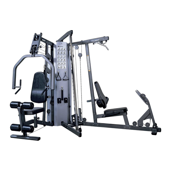
- Page 1 A s s e m b l y & Owner’s Guide ST710 MULTI-STATION GYM...
-
Page 3: Table Of Contents
A S S E M B L Y G U I D E ASSEMBLY GUIDE ....4 HARDWARE BAGS ....6 STEP 1: ORANGE BAG . -
Page 4: Assembly Guide
A s s e m b l y & O w n e r ’ s G u i d e ST710 MULTI-STATION GYM To avoid possible damage to this Multi-Station Gym, please follow these assembly steps in the correct order. Before proceeding, find your new Multi-Station Gym serial number located on the side of the leg press floor support (AC3), and enter here: Refer to this number when calling for service, and enter this serial number on your Warranty Card and in your... - Page 5 STEP STEP STEP STEP General Warning Decal STEP STEP STEP Serial # STEP Pinch Point Decal STEP...
-
Page 6: Hardware Bags
ORANGE BAG M10 x 78 Bolt Quantity: 4 M10 x 60 Bolt Quantity: 2 BLUE BAG M10 x 25 Bolt Quantity: 4 M10 x 62 Bolt Quantity: 6 M10 x 72 Bolt Quantity: 1 HARDWARE INCLUDED M6 x 8 Set Screw Quantity: 4 12 x 26 x 2 Flat Washer... - Page 7 HARDWARE INCLUDED PINK BAG M10 x 62 Bolt 10.2 x 22 x 2 M10 Nylon Nut Quantity: 4 Flat Washer Quantity: 6 Quantity: 10 GREEN BAG M10 x 62 Bolt 10.2 x 22 x 2 M10 Nylon Nut Quantity: 6 Flat Washer Quantity: 10 Quantity: 26...
- Page 8 HARDWARE INCLUDED BLACK BAG 10.2 x 22 x 2 12.2 x 21 x 2.5 M10 Nylon Nut 12 x 26 x 2 Flat Washer Lock Washer Quantity: 8 Flat Washer Quantity: 16 Quantity: 2 Quantity: 2 M10 x 62 Bolt M12 x 25 Bolt Quantity: 8 Quantity: 2...
- Page 9 HARDWARE INCLUDED YELLOW BAG 10.2 x 18.4 x 2.5 10.2 x 22 x 2 Lock Washer Flat Washer Accessory Storage Hook Add-on Weight Storage Posts Quantity: 2 Quantity: 2 (illustration not to scale) (illustration not to scale) Quantity: 3 Quantity: 2 M5 x 15 Bolt M5 x 15 Screw M8 x 20 Bolt...
- Page 10 HARDWARE INCLUDED RED BAG 10.2 x 22 x 2 Flat Washer M10 x 25 Bolt Quantity: 9 Quantity: 3 Pull Pin B (illustration not to scale) Quantity: 1 M6 x 8 Set Screw Quantity: 1 M10 Nylon Nut M10 x 68 Bolt Quantity: 6 Quantity: 2 M10 x 125 Bolt...
-
Page 11: Step 1: Orange Bag
ORANGE BAG STEP NOTE: Leave all hardware partially loose, until the end of Step 6. • Attach the press arm foot (AC5) to the press arm floor support (AC1) using two bolts (M10x65), flat washers (10.2x22x2), and two nylon nuts (M10). •... -
Page 12: Step 2: Blue Bag
BLUE BAG STEP • Place the center connecting support (AC6) in between the functional arm floor support and the leg press arm floor support, aligning the holes. Slide two bolts (M10x62) with flat washers (10.2x22x2) through the holes into the functional arm floor support. -
Page 13: Step 3: Weight Stack
WEIGHT STACK STEP • Place weight stack bumpers (Q05) over the holes of both weight stack support blocks (AK3). Place the guide rods over and through the rubber weight plate bumpers into the weight stack support block. Use caution when adding the weight plates. -
Page 14: Step 4: Pink Bag
PINK BAG STEP • With angled end down and pulley brackets facing weight stack, place the press arm upright (AB2) over the press arm floor support (AC1), aligning the holes in both components. Slide bolts (M10x62) with flat washers (10.2x22x2) through holes and secure each of the bolts with another flat washer and two nylon nuts (M10). -
Page 15: Step 5: Green Bag
GREEN BAG STEP • Slide a weight stack upper block (AK2) onto the guide rods of the press arm weight stack. See diagram for orientation. Take the press arm overhead tube (AB3) and place in the bracket on top of the press arm upright (AB2). -
Page 16: Step 6: Black Bag
BLACK BAG STEP • Attach the press arm swing arm (AD2) to the press arm overhead tube (AB3) using one of the axles provided. Center the shaft in the connection and secure with a sleeve (lining the flat surface up with the flat inside of swing arm), a bolt (M12x25), a flat washer (12x26x2), and a lock washer (12.2x21x2.5). -
Page 17: Step 7 Cable #1
CABLE #1 STEP Thread the bolt on the end of the cable (the end with the permanent bolt affixed) to the header plate a minimum of 1”, after slipping the closed loop of the weight selector pin tether over the attached nuts. Remove the slotted bolt and nut from the opposite end of the cable. -
Page 18: Step 8 Cable #2
CABLE #2 STEP NOTE: You will need to remove pulleys H, I, J, K, L, and M to route cable #2. • Route the loop only end of the cable through the following pulleys in the specified order: over pulley I, over J, under floating pulley housing H, over K, under L, and under M. -
Page 19: Step 9 Cable #3
CABLE #3 STEP Remove the slotted bolt and nut from the end of the cable. Route this end through the pulleys in the specified order: thru the center of pulleys N & O (dual transition pulley assembly), under P, under Q, over the front of R, under the back of S (top half of dual floating pulley assembly), over the back of T, and over the back of U. -
Page 20: Step 10: Cable #4
CABLE #4 STEP Remove the slotted bolt and nut from one end. Thread the opposite end, slotted bolt into the attachment point at the bottom of the main center upright (AB1) a minimum of 0.5”. Tighten the nut against the attachment point. Route the other end through the following pulleys in the order specified: over the front of pulley V, under the back of W, over the... -
Page 21: Step 11: Cable #5
CABLE #5 STEP Remove the slotted bolt and nut from the end of the cable. Route this end through the following pulleys in the specified order: Up through the center of the leg press overhead tube, over pulley BB, over CC, down through the center of the tube, under floating pulley DD, over EE, and under the front of FF. -
Page 22: Step 12: Cable #6 (1/4" Diameter)
CABLE #6 STEP (1/4” diameter) NOTE: You will need to remove pulleys GG, HH, II, and JJ to route cable #6. • Thread the bolt a minimum of 0.5” into pulley DD. Tighten nut to pulley housing. Route the cable through the specified pulleys in the following order: under GG, under HH, over II, and under JJ. -
Page 23: Step 13: Yellow Bag
YELLOW BAG STEP • Slide the slip on nuts (Z31) over the 8 holes of the 4 attachment clips (Z30). Fasten one end of the 4 attachment clips (Z30) to the inside of the right hand weight stack shield (Q01 @ A, B, C, and D) with four screws (M5x15). -
Page 24: Step 14: Red Bag
RED BAG STEP • Slide the post (AH5) into the tube (AH1). Insert set screw (M6x8) and tighten, after centering the post. Insert plastic cap (H26). • Insert the knee pad post (AH1) into the bracket on the press arm floor support (AC1). -
Page 25: Step 15: Light Blue Bag
LIGHT BLUE BAG STEP • Slide a large disc onto extension of knee pad post (AH1). Slide a round pad onto the extension, followed by a small disc. Secure with a bolt (M8x20) and a flat washer (8.4x15x1.6). Repeat this process to attach pads to other extension on knee pad post, and extensions on leg curl post (AH2). -
Page 26: Effective Resistance
EFFECTIVE RESISTANCE 100% 100% 200%... - Page 27 Weight Stack 200% 100% 13.5 22.5 31.5 40.5 49.5 58.5 67.5 76.5 85.5 94.5 103.5 112.5 121.5 130.5 139.5 148.5 157.5 166.5 175.5 184.5 193.5 12.5 17.5 22.5 27.5 32.5 37.5 42.5 47.5 52.5 57.5 62.5 67.5 72.5 77.5 82.5 87.5 92.5 97.5...
-
Page 28: Resistance Training Benefits
Use this manual to guide you through the basic exercises you can perform on your VISION FITNESS gym. To achieve maximum results and avoid possible injury, consult a fitness professional to formulate a complete exercise program. -
Page 29: Training Programs
SPRINT 8 This program is exclusive to VISION FITNESS exercise equipment. This is a program that stresses high intensity, a moderate amount of resistance, and as many repetitions that a person can perform in a specified period of time (usually 20-30 seconds). -
Page 30: Stretching
STRETCHING Flexibility Training is not associated with fitness as often as cardiovascular exercise or Strength Training, even though it is just as important. A good stretching program will help to maintain flexibility of the hips and lower back. A flexible person will be less likely to injure themselves in common activities, such as reaching, twisting and turning, or in uncommon activities such as the annual softball tournament. - Page 31 BICEP/CHEST STRETCH Grasp an immovable object (pole or corner of a wall) with your feet planted firmly and evenly on the floor. With the palm of your stretched side facing forward, rotate your hips away from that hand. Be careful not to rotate too far or hyperextend the elbow joint.
-
Page 32: Included Accessories
INCLUDED ACCESSORIES Long Lat Bar Quantity: 1 Foot Cuff Short Bar Quantity: 1 Quantity: 2 5# Add-on Weight Sport Handle Co-Molded Handle Quantity: 2 Quantity: 1 Quantity: 1... -
Page 34: Press Arm Station Exercises
PRESS ARM STATION EXERCISES LEG EXTENSION (LOWER QUADRICEP GROUP) While holding onto the seat, disengage and hold the pull pin that locates it vertically. Transition the seat to the hole that allows your legs to be bent at a 90 degree angle, when seated. Engage and tighten the pull pin knob. - Page 35 SEATED SHOULDER PRESS (DELTOIDS AND TRICEPS) Disengage and hold the seat pull pin. Position the seat at a height, where the horizontal handles are at shoulder level. Engage and tighten the pull pin. Disengage and hold the seatback angle adjustment pull pin. Engage the pin in the last hole.
-
Page 36: Center Station Exercises
CENTER STATION EXERCISES LOW CABLE CURL (BICEPS) Disengage and hold the handle of the dual transitioning pulley. Position the handle in hole # 1, making sure the pin fully engages. Attach the single swivel, short bar onto the karabiner. Reach down and grasp the bar evenly with both hands (underhand grip). - Page 37 HIP ADDUCTION (GRACILIS, ADDUCTOR LONGUS & MAGNUS, PECTINEUS OR GROIN/ADDUCTOR GROUP) Disengage and hold the handle of the dual transitioning pulley. Position the handle in hole # 1, making sure the pin fully engages. Attach the foot cuff with the loop down. Place the foot of the working leg into the cuff, with the back portion of the strap against your heel and the loop around the bottom of your foot.
- Page 38 CENTER STATION EXERCISES (continued) WOOD CHOP (LATISSIMUS DORSI, LUMBAR & THORACIC MUSCLES OF THE BACK, TRANSVERSE ABDOMINIS, AND OBLIQUES) Disengage and hold the handle of the dual transitioning pulley. Position at a point above your head, making sure the pin fully engages. Position your body so that it is side by side, in relation to the center upright.
-
Page 39: Leg Press/Lat Pulldown Exercises
LEG PRESS/LAT PULLDOWN STATION EXERCISES LEG PRESS (QUADRICEPS, HAMSTRINGS, AND GLUTEALS) Disengage and hold the pull pin of the seat back. Position in the hole that provides the desired range of motion. Engage and tighten the pull pin. Sit on the seat with your lower back firmly against the seat back. Place your feet at the desired width in the center (height) of the footplate. -
Page 40: Maintenance Schedule
MAINTENANCE SCHEDULE FOR BEST PERFORMANCE WE RECOMMEND THE FOLLOWING MAINTENANCE SCHEDULE: Check the integrity and function of the following parts. Replace all worn components immediately. CHECK END FITTINGS AND CABLE JACKET COATING. CHECK TIGHTNESS OF WEIGHT STACK LOCKING NUT. REPLACE CABLES ANNUALLY. WIPE DOWN AND DRY. -
Page 41: Commercial Warranty
WARRANTY REGISTRATION Your warranty card must be completed and sent to VISION FITNESS before a warranty claim can be processed. You may also register via our website at www.visionfitness.com. Inside the enclosed warranty card you will find a customer survey. Your care in completing the survey will be of value to us in serving you in the future. - Page 48 500 South CP Avenue • P.O. Box 280 • Lake Mills. WI 53551 toll free 800.335.4348 • phone 920.648.4090 • fax 920.648.3373 www.visionfitness.com ©2007 Vision Fitness. All Rights Reserved. 2.07 OM18.41PRD REV2...