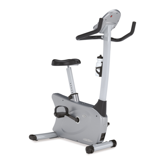
Vision Fitness E3200 Frame 9 Service Manual
Hide thumbs
Also See for E3200 Frame 9:
- Owner's manual (72 pages) ,
- Assembly manual (8 pages) ,
- Manuel du propriétaire (56 pages)
Summary of Contents for Vision Fitness E3200 Frame 9
- Page 1 BECS_9 Service manual (E3200 Frame_9/E1500 Frame_9/R2250 Frame_9/ R1500 Frame_9/X6200 Frame_9/X1500 Frame_9/ X20 Frame_09)
-
Page 2: Table Of Contents
TABLE OF CONTENTS CHAPTER 1: SERIAL NUMBER LOCATION……………………………..….……….3 CHAPTER 2: CONSOLE INSTRUCTION CONSOLE HARDWARE DESCRIPTIONS …………………………….………….……4 SIMPLE CONSOLE DESCRIPTIONS…………………………………………………...5 USE THE SIMPLE CONSOLE……………………………………………………………5 CHAPTER 3: ENGINEERING MODE ENGINEERING MODE………………………………………………………….…….…..6 CHAPTER 4: ELECTRON DIAGRAMS RB130-2KM-C(BECS_9) …..………………………………………………….….……..8 CB142B-2KM-F(E3200 FRAME_9) …….…………………………………….….……..9 CB143-2KM-F(E1500 FRAME_9) …..….…………………………………….….…….10 RB135-2KM-F(R2250 FRAME_9) …..….…………………………………….….…….11... -
Page 3: Chapter 1 Serial Number Location
CHAPTER 1 SERIAL NUMBER LOCATION 1.1 Serial Number Location (E3200 Frame_9/E1500 Frame_9/R2250 Frame_9/ R1500 Frame_9/X6200 Frame_9/X1500 Frame_9/X20 Frame_09) Serial Number Placement... -
Page 4: Chapter 2 Console Instruction
CHAPTER 2 CONSOLE INSTRUCTION 2.1 CONSOLE HARDWARE DESCRIPTIONS A. POWER SWITCH Turn off power to your console if it will not be used for an extended period of time. B. MILES/KILOMETER SWITCH Changes your exercise feedback to the English or Metric system. C. -
Page 5: Simple Console Descriptions
2.2 SIMPLE CONSOLE DESCRIPTIONS A. PROFILE DISPLAY This window provides an 8x12 block profile of your program profile. Each horizontal row of blocks represents your segment time, which is total workout time divided by twelve. Each vertical column of blocks represents the resistance level, which is one block for every two levels. -
Page 6: Chapter 3 Engineering Mode
CHOOSING EXERCISE TIME The default exercise time will be flashing in the TIME window. Use the UP▲ or DOWN▼ keys to set your desired workout time. Press ENTER to select. CHOOSING RESISTANCE LEVEL The default resistance level will be flashing in the LEVEL window. - Page 7 Mode Function Description START LED on (Fig. A) START LED off (Fig. B) Eng 1 Display Test START START “▲”/ “▼” display on window Hold “START” 3 sec back to “Engineering Menu” START Heart rate, Accumulated Time/Distance to be presented on the console. Eng 2 Machine Test Hold “ENTER”...
-
Page 8: Chapter 4 Electron Diagrams
CHAPTER 4 ELECTRON DIAGRAMS 4.1 RB130-2KM-C(BECS_9) -
Page 9: Cb142B-2Km-F(E3200 Frame_9)
4.2 CB142B-2KM-F(E3200 FRAME_9) -
Page 10: Cb143-2Km-F(E1500 Frame_9)
4.3 CB143-2KM-F(E1500 FRAME_9) -
Page 11: Rb135-2Km-F(R2250 Frame_9)
4.4 RB135-2KM-F(R2250 FRAME_9) -
Page 12: Rb133-2Km-F(R1500 Frame_9)
4.5 RB133-2KM-F(R1500 FRAME_9) -
Page 13: Ep225-2Km-F(X6200 Frame_9)
4.6 EP225-2KM-F(X6200 FRAME_9) -
Page 14: Ep224-2Km-F(X1500 Frame_9)
4.7 EP224-2KM-F(X1500 FRAME_9) -
Page 15: Ep240-2Km-F(X20 Frame_9)
4.8 EP240-2KM-F(X20 FRAME_9) CHAPTER 5 ERROR CODE 5.1 E1: No connect ECB motor CHAPTER 6 TROUBLESHOOTING 6.1 No RPM Reason: 1. Bad connection between the console wire and the console 2. Speed Sensor wire is defective. 3. Speed Sensor Assembly Un-properly. 4. - Page 16 Solution: 1. Re-connect the console wire 2. Check if the speed sensor wire works. Enter Engineering Mode (See Chapter 3), and scroll to ENG 2 (Machine Test).Press the key “ENTER”, and then pedal the machine. If the left 8 blocks are flashed (Fig. E), the speed sensor works well. If the left 8 blocks are not flashed, the speed sensor wire is defective or it is not well-assembled.
- Page 17 5. Use a multi-meter to check if the console wire is conductive. If not, the console wire is defective, and replace it. 6. Replace the console set if all above can not resolve the issue. . 6.2 Resistance Inaccurate Reason: 1.
- Page 18 Adjust the steel cable (Fig. J) B: Outside Magnetic Brake Control System: Adjust the resistance to the max. The distance between the magnets and the pulley shall be 1.8-2mm. If the distance is not in this range, adjust it to the proper position by moving the two screws at the frame. (Fig. K) Distance away from magnets : 1.8~2.0mm Adjusted screws at the...
- Page 19 1. Check if the LED at the adaptor is lit. If it is not, try a different outlet. (Fig. L) - If the LED is still not lit with a known good outlet, the adaptor is defective and replace it. (Fig.
- Page 20 (Fig. O) 3.If the console cable is good and the console is still not lit, the PCB is defective and replace the console.


