
Related Manuals for Rangemaster Classic Series


Summary of Contents for Rangemaster Classic Series
-
Page 1: Installation Instructions
USER GUIDE & INSTALLATION INSTRUCTIONS Classic, Kitchener and Professional+ 90 Dual Fuel U110668 - 04... - Page 2 Terms & Conditions 1. This is my Rangemaster is open to residents of UK mainland only, aged 18 years & over. 2. All entries should be submitted to the advertised e-mail address, or Rangemaster UK Facebook, Instagram or Twitter page using the advertised hashtag &...
-
Page 3: Table Of Contents
Contents Before You Start... Troubleshooting Personal Safety 10. Installation Electrical Connection Safety Dear Installer If You Smell Gas Safety Requirements and Regulations Peculiar Smells Provision of Ventilation Cooling Fan Location of Cooker Ventilation Conversion Maintenance Positioning the Cooker Grill/Glide-out Grill™ Care Moving the Cooker Cooker Care Lowering the Two Rear Rollers... -
Page 5: Before You Start
Before You Start... Your cooker should give you many years of and will retain heat even after you have trouble-free cooking if installed and operated stopped cooking. Care should be taken to correctly. It is important that you read this avoid touching heating elements. - Page 6 WARNING: THE APPLIANCE MUST BE Fig. 1.1 EARTHED. Note: The cooker must be connected to the correct electrical supply as stated on the voltage label on the cooker, through a suitable cooker control unit incorporating a double- 10 mm² max pole switch, having a contact separation of at least 3 mm in all poles.
-
Page 7: If You Smell Gas
In your own interest and that of safety, it is minutes with the grill pan in position, pushed • law that all gas appliances be installed by a fully back and the grill door open. qualified person(s). Make sure the room is well ventilated to the outside air (see ‘Ventilation’... - Page 8 DO NOT use hotplate protectors, foil or DO NOT use the top of the flue (the slot • • hotplate covers of any description. These along the back of the cooker) for warming may affect the safe use of your hotplate plates, dishes, drying tea towels or burners and are potentially hazardous to softening butter.
-
Page 9: Oven Shelves
Make sure the shelves are pushed firmly • Fig. 1.3 to the back of the oven. DO NOT close the door against the oven shelves. DO NOT use aluminium foil to cover • shelves, linings or the oven roof. ArtNo.324-0001 Steam burst When the oven is on, DO NOT leave the •... -
Page 10: Grill/Glide-Out Grill™ Care
DO NOT mix different cleaning products Grill/Glide-out Grill™ Care • – they may react together with hazardous When using the grill, make sure that the • results. grill pan is in position and pushed fully in, otherwise the control knobs may become All parts of the cooker can be cleaned with •... -
Page 11: Cooker Overview
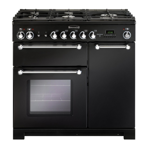
Cooker overview Fig. 2.1 The 90 dual fuel cooker (Fig. 2.1) has the following features: Fig. 2.2 5 hotplate burners including a wok burner Control panel Glide-out Grill™ A main programmable fan oven Tall fan oven Hotplate burners The drawing by each of the central knobs indicates which burner that knob controls. -
Page 12: Wok Burner
The igniter should spark and light the gas. Keep holding the Fig. 2.3 knob pressed in to let the gas through to the burner for about ten seconds. If, when you let go of the control knob, the burner goes out, then the FSD has not been bypassed. -
Page 13: Wok Cradle
Wok cradle (optional) Fig. 2.9 The wok cradle is designed to fit a 35 cm wok. If you use a different wok, make sure that it fits the cradle. Woks vary very widely in size and shape. It is important that the wok sits down on the pan support –... -
Page 14: The Teppanyaki
The Teppanyaki (optional on Classic, Kitchener and Fig. 2.15 Professional+) The griddle fits the left-hand well, front to back (Fig. 2.15). It is designed for cooking food on directly. DO NOT use pans ArtNo.311-0044 - Positioning the griddle 09 of any kind on it. The griddle surface is non-stick and metal cooking utensils (e.g. -
Page 15: Glide-Out Grill
Glide-out grill™ Fig. 2.16 CAUTION: This appliance is for cooking purposes only. It must not be used for other purposes, for example room heating. Accessible parts may be hot when the grill is in use. Young children should be kept away. ArtNo.331-0001Grill pan pulled forwards Open the door and pull the grill pan carriage forward using the handle (Fig. -
Page 16: Ovens
Ovens Fig. 2.21 The clock must be set to the time of day before the programmable ovens will work. See the following section on ‘The Clock’ for instructions on setting the time of day. References to ‘left-hand’ and ‘right-hand’ ovens apply as Fan oven viewed from the front of the appliance. -
Page 17: Accessories
Accessories Fig. 2.23 Oven shelves – Left-hand (Main) oven Shelf guard The oven shelves (Fig. 2.23) can be easily removed and refitted. Pull the shelf forward until the back of the shelf is stopped by the shelf stop bumps in the oven sides (Fig. 2.24). Front Lift up the front of the shelf so the back of the shelf will pass under the shelf stop and then pull the shelf forward (Fig. -
Page 18: 3. 2 Button - Rotary Clock
3. 2 Button - rotary clock The clock must be set to the time of day before the oven Fig. 3.1 ArtNo.300-0005 2BC will work. minute minder setting Setting the Clock Once the cooker is connected and switched on, the display will start to flash. - Page 19 To stop the oven at a specific time of day Fig. 3.5 You have set the required temperature and function mode and you would like the oven to automatically stop. TOP TIP Make a note of the current time so you do not forget. Turn the Timer (A) knob to the Stop Time (G) setting.
- Page 20 To start and stop the oven automatically Fig. 3.9 The timer allows you to automatically start and stop by a combination of the length of the cooking time and the stop time. Giving you the flexibility to cook casseroles etc while you are out.
-
Page 21: Button Clock
3 Button clock Using the clock Fig. 4.1 You can use the clock to turn the programmable oven on and off. The clock must be set to the time of day before the oven will work. NOTE: When using the timer functions, first set the clock as ArtNo.306-0001 - 3-button clock required before setting the oven temperature. - Page 22 When the ‘stop time’ is reached an alarm will sound and Fig. 4.7 the oven will stop working. The word ‘AUTO’ will flash on the display (Fig. 4.6). Press any button to stop the alarm and return to manual cooking. If the alarm is not stopped, it will stop ArtNo.306-0001 - 3-button clock automatically after 7 minutes.
-
Page 23: Button Clock
6 Button clock Using the clock Fig. 5.1 You can use the timer (Fig. 5.1) to turn the oven(s) on and off. The clock must be set to the time of day before the oven(s) will work. ArtNo.302-0002 - 6BC annotated The oven can be switched on when the cook symbol [ ] is displayed. - Page 24 The clock will now control the cook period of your oven(s). Fig. 5.7 Fig. 5.8 The [ ] symbol and [AUTO] will be displayed. Once the ‘cook period’ is reached, the beeper sounds and the [AUTO] symbol flashes. Turn the oven control knob to 0 and then press any button to stop the beep.
-
Page 25: Cooking Tips
Cooking tips Tips on cooking with the timer General oven tips If you want to cook more than one dish, choose dishes that The wire shelves should always be pushed firmly to the back require approximately the same cooking time. However, of the oven. -
Page 26: Cooking Table
Cooking Table The oven control settings and cooking times given in the table below are intended to be used as a Top (T) guide only. Individual tastes may require the temperature to be altered to provide a preferred result. ArtNo.050-0007 Centre (C) Oven shelf positions Food is cooked at lower temperature in a fan oven than in a conventional oven. -
Page 27: Cleaning Your Cooker
Cleaning your cooker Essential Information Fig. 8.1 Isolate the electricity supply before carrying out any thorough cleaning. Allow the cooker to cool. NEVER use paint solvents, washing soda, caustic cleaners, biological powders, bleach, chlorine based bleach cleaners, coarse abrasives or salt. DO NOT mix different cleaning products –... -
Page 28: The Griddle
The Griddle Fig. 8.5 ArtNo.331-0003 Grill frame out, no pan Always clean the griddle after use. Allow it to cool completely before removing. Immerse the griddle plate in hot soapy water. Use a soft cloth or, for stubborn stains, a nylon washing up brush. -
Page 29: Ovens
Glass Fronted Door Panels Fig. 8.9 The oven door front panels can be taken off so that the glass panels can be cleaned. Move the cooker forward to gain access to the sides (see the ‘Moving the Cooker’ section under ‘Installation’). -
Page 30: Cleaning Table
Cleaning table Cleaners listed are available from supermarkets or electrical retailers as stated. For enamelled surfaces use a cleaner that is approved for use on vitreous enamel. Regular cleaning is recommended. For easier cleaning, wipe up any spillages immediately. Hotplate Part Finish Recommended Cleaning Method... -
Page 31: Troubleshooting
Troubleshooting Hotplate/Cooktop ignition or hotplate burners faulty Food is cooking too slowly, too quickly, or burning Is the power on? Is the clock illuminated? Cooking times may differ from your previous oven. If not, there maybe something wrong with the power supply. Check that you are using the recommended temperatures and shelf positions –... - Page 32 Oven light is not working Fig. 9.1 The bulb has probably burnt out. You can buy a replacement bulb (which is not covered under the warranty) from a good electrical shop. Ask for a 40W - 230V halogen lamp (G9) (Fig.
-
Page 33: 10. Installation
INSTALLATION Check the appliance is electrically safe and gas sound when you have finished. 10. Installation Dear Installer In the UK the cooker must be installed in accordance with: Before you start your installation, please complete the details below, so that, if your customer has a problem relating to •... -
Page 34: Location Of Cooker
INSTALLATION Check the appliance is electrically safe and gas sound when you have finished. Location of Cooker Checking the Parts: Griddle Plate The cooker may be installed in a kitchen/kitchen diner but (Supplied with Classic and 3 pan supports NOT in a room containing a bath or shower. Professional+, optional on Kitchener) This appliance is designed for domestic cooking only. -
Page 35: Positioning The Cooker
INSTALLATION Check the appliance is electrically safe and gas sound when you have finished. Positioning the Cooker ArtNo.090-0009 - 90 2BC cooker min spacings Fig. 10.1 Fig. 10.1 and Fig. 10.2 show the minimum recommended 75 mm 75 mm distance from the cooker to nearby surfaces. 650 mm The cooker should not be placed on a base. -
Page 36: Lowering The Two Rear Rollers
INSTALLATION Check the appliance is electrically safe and gas sound when you have finished. Lowering the Two Rear Rollers Fig. 10.5 To adjust the height of the rear of the cooker, first fit a 13 mm spanner or socket wrench onto the hexagonal adjusting nut (Fig. -
Page 37: Conversion To Another Gas
INSTALLATION Check the appliance is electrically safe and gas sound when you have finished. Conversion to Another Gas If the appliance is to be converted to another gas do the conversion at this point. See the conversion section of these instructions. -
Page 38: Gas Connection
INSTALLATION Check the appliance is electrically safe and gas sound when you have finished. Gas Connection Fig. 10.11 This must be in accordance with the relevant standards. Pipework Pipework The flexible hose (not supplied with the cooker) must be in accordance with the relevant standards. Hoses may be purchased at most builders’... -
Page 39: Electrical Connection
INSTALLATION Check the appliance is electrically safe and gas sound when you have finished. Electrical Connection Current Operated Earth Leakage Breakers The combined use of your cooker and other domestic The cooker must be installed by a qualified electrician, in appliances may cause nuisance tripping, so we recommend accordance with all relevant British Standards/Codes of that the cooker is protected on an individual RCD (Residual... -
Page 40: Final Fitting
INSTALLATION Check the appliance is electrically safe and gas sound when you have finished. Final Fitting Fig. 10.15 Fitting the Handles and Handrail (Classic Deluxe) Remove the 4 mm Allen screws from the doors (Fig. 10.15). Fit the door handles and secure using the 4 mm screws. ArtNo.215-0026 - Handle gaskets fixed The handles should be above the fixings. -
Page 41: 11. Conversion To Lp Gas
WARNING – SERVICING TO BE CARRIED OUT ONLY BY AN AUTHORISED PERSON Disconnect from electricity and gas before servicing. Check appliance is safe when you have finished. 11. Conversion to LP Gas Check the ‘Technical Data’ section at the back of the book Fig. -
Page 42: Pressure Testing
WARNING – SERVICING TO BE CARRIED OUT ONLY BY AN AUTHORISED PERSON Disconnect from electricity and gas before servicing. Check appliance is safe when you have finished. Pressure Testing Connect the appliance to the gas supply. The gas pressure can be measured at one of the hotplate burner jets (not a wok burner). -
Page 43: 12. Circuit Diagram
12. Circuit Diagram P095199 P095199 P095199 The connections shown in the circuit diagram are for single-phase. The ratings are for 230 V 50 Hz. Code Description Code Description Code Colour Grill front switch Right-hand oven element Blue Grill energy control Oven fan Brown Left Hand Grill Element... -
Page 44: 13. Technical Data
13. Technical Data THE COOKER IS CATEGORY: CatII 2H3+ . It is supplied set for group H natural gas. A conversion kit from NG to LP is available for the cooker. INSTALLER: Please leave these instructions with the user. DATA BADGE LOCATION: Cooker back, serial number repeater badge below oven door opening. COUNTRY OF DESTINATION: GB, IE. -
Page 45: Hotplate Ratings
Hotplate Ratings Natural Gas 20 mb L.P. Gas Bypass Hotplate Screw* Injector Injector internal 78 internal 53 Wok burner 3.5 kW 3.5 kW (246 g/h external 126 external 82 Rapide/ Large Burner 3 kW 3.0 kW (210 g/h) Semi Rapide / Medium Burner 1.7 kW 1.7 kW (119 g/h) Auxiliary / Small Burner... -
Page 46: Hotplate Efficiency
Hotplate Efficiency Brand Rangemaster Classic Model Identification Kitchener Professional + Size Type Dual Fuel Type of Hob Number of gas burners Auxiliary / Small Burner (EE gas burner) Semi Rapide / Medium Burner (EE gas burner) Semi Rapide / Medium Burner (EE gas burner) -
Page 47: Oven Data
Oven Data Brand Rangemaster Model identification Classic Mass Model identification Kitchener Mass Model identification Professional+ Mass Type of oven Electric Number of cavities Left-hand Efficiency Fuel type Electric Cavity type Fanned Power - conventional Power - forced air convection Volume... -
Page 55: Spare Parts
• Has not been repaired by persons or organisations other than those authorised to act on behalf of AGA Rangemaster. Date of Purchase Exceptions: • Items not included under the free 1 year guarantee Installer’s Name &... - Page 56 Registered Office: c/o Aga Rangemaster, Meadow Lane, Long Eaton, Nottingham, NG10 2GD Rangemaster continuously seeks improvements in specification, design and production of products and thus, alterations take place periodically. Whilst every effort is made to produce up-to-date literature, this brochure should not be regarded as...