
Related Manuals for ESI ESRTPRF


Summary of Contents for ESI ESRTPRF
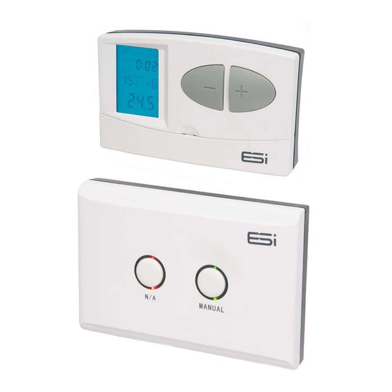
- Page 1 ESRTPRF Wireless Programmable Room Thermostat, with Delayed & Optimum Start User and Installation Instructions...
-
Page 3: Table Of Contents
INDEX User Instructions What is a Programmable Room Thermostat? Introduction to the ESRTPRF What is Delayed Start? What is Optimum Start? Quick Operating Guide Factory Pre-Set Programme Choosing Between 7 Day, 5/2 Day & 24hr Operation 7 Permanent Manual Overrides... - Page 4 INDEX Installation Instructions Technical Data Installation Safety Instructions General Safety Instructions Maintenance Safety Notice Fitting the Programmable Room Thermostat Fitting the Receiver Wiring Diagram Receiver Manual Override Switching Sensitivity Option...
-
Page 5: User Instructions
User Instructions... - Page 6 What is a Wireless Programmable Room Thermo- stat? ...An explanation for householders Put simply a Programmable Room Thermostat is a timer and thermostat combined in one unit. With a standard timer you choose your heating ON times and set your room thermostat (fitted usually away from the timer) to the desired comfort temper- ature required.
-
Page 7: Introduction To The Esrtprf
Introduction to the ESRTPRF The ESRTPRF is an easy to install and use 7 Day, 5/2 Day or 24 Hr Wireless Programmable Room Thermostat which offers up to six time and temperature changes each day, with different programmes available for weekdays and... - Page 8 time that the home should be at the desired temperature. Up to 10% of domestic energy costs can be saved, as the warm up time is automatically reduced according to the ambient temperature. Many homeowners set their heating to start a couple of hours before getting up to avoid waking up to a cold house.
-
Page 9: Quick Operating Guide
Quick Operating Guide Accepts changes (SET) ① Places Thermostat into Frost Protection Mode (MAN) ② Selects Programme (PROG) ③ Resets Unit to Default Settings (RESET) ④ ⑤ Blue Backlight Illuminates Display (LIGHT) ⑥ Sets Time and Date (DAY) Selects Operation Mode (HOLD) ⑦... - Page 10 Day Display Time Display User Set Temperature Low Battery Warning Heating ON Display Room Temperature Holiday Mode Display Programme Events Display Manual Mode Display Symbols Figure 1 (Fig.1) Fig.2...
-
Page 11: Factory Pre-Set Programme
Factory Pre-Set Programme This Wireless Programmable Room Thermostat has been designed to be a simple to use thermostat, requiring minimal user intervention with a pre-programmed heating profile. The pre-set heating times and temperatures will suit most households (see table below). To accept the factory pre-set settings, press the SET button which will revert the thermostat to Run Mode (the colon (:) in the LCD display). -
Page 12: Choosing Between 7 Day, 5/2 Day & 24Hr Operation
Choosing Between 7 Day, 5/2 Day & 24Hr Operation 1. Press and hold SET then press PROG until days of the week are flashing. 2. Press either + or – buttons to move the flashing day symbols until you get the operation you desire:- 7 Day operation is shown by just one day flashing (e.g Monday-1) 5/2 Day operation is shown by 1,2,3,4,5 flashing (5 Day) -
Page 13: Temporary Manual Overrides
Temporary Manual Overrides 1. To temporarily override the Wireless Programmable Room Thermostat status or temperature press the + or – buttons. The hand symbol ① (Fig 4.) will appear on screen. 2. Press the + button to increase the set temperature in increments of 0.5°c and/or press the - button to decrease the set temperature in increments of 0.5°c. -
Page 14: Holiday Mode
Holiday Mode Holiday mode saves energy by letting you reduce the temperature for 1 to 99 days while you are away from home, resuming normal operation on your return. To set the Holiday Mode: 1. Press + or – to set the desired temperature. 2. -
Page 15: Party Mode
Party Mode The party mode temporarily overrides the programme to maintain a comfortable temperature whilst you entertain guests. When the time has expired, the temperature and programme will revert to the pre-set schedule. To set the Party Mode: 1. Press + or – to set the desired temperature. 2. -
Page 16: Setting The Time And Date
Setting the Time and Date The time and date are factory set so it will not normally be necessary to do this on site. Changes between summer and winter time are handled automatically by the unit. 1. Press SET to make sure the programmer is in Run Mode. 2. -
Page 17: Changing The Programme: 5/2 Day
6. Once Monday’s time and temperatures have been adjusted to desired settings and 1 (Monday) is flashing, repeat steps 2 to 4 until all 7 days of the week have been set to desired times and temperatures. 7. When all 7 days, time and temperatures have been set to desired settings, press SET to confirm settings and return the programmer to Run Mode. - Page 18 adjusted to desired settings, press SET to confirm changes and continue to press until the programmer returns to Run Mode. Sat—Sun 1. Press and hold SET then press PROG until the days of the week are flashing (1,2,3,4,5,6,7) then release SET button. 2.
-
Page 19: Changing The Programme: 24Hr
Changing the Programme: 24 Hr 1. Press and hold SET then press PROG until all the days of the week are flashing (1, 2, 3, 4, 5, 6 ,7) ① (Fig.10). 2. Press PROG once and the time will flash ② (Fig.10). Adjust the time for P1 using the +/–... -
Page 20: Using The Copy Function
Using the Copy Function The unit is provided with a copy function which allows an adjusted programme to be copied to another day or set of days. This avoids the necessity of re-entering a desired programme for another day or sets of days. To operate the copy function 1. -
Page 21: Battery Replacement
Battery Replacement When the low battery symbol flashes in the LCD display (Fig.2, page 5), the batteries need to be replaced as soon as possible. To replace the batteries, remove the Wireless Programmable Room Thermostat from its back-plate. The battery compartment is located on the main part of the thermostat. - Page 22 Installer Instructions...
-
Page 23: Technical Data
Technical Data Wireless Programmable Room Thermostat Programming 7 Day, 5/2 Day & 24Hr 2 x 1.5V Alkaline Batteries Power Supply (type: AA size) Temperature NTC 10k ῼ+/- 1% at 25oC Sensor Type Switching Sensitivity +/-0.2oC or 0oC/-0.2oC Temperature 7oC to 34oC Adjustment Range Transmission Distance Approx. - Page 24 Receiver Fixing Easy Fit Back Plate Power Supply Voltage 230VAC, 50Hz Power Consumption 6 (2)A. 230VAC SPDT (Volt Free Contact Type changeover contacts) Plastic Thermoplastic, flame retardant Protection Rating IP30 135mm(L) x 90mm(W) Dimensions x 33mm(D) EN60730-1 EN 60730-2.7, EMC Directive 2004/108/EC, LVD Complies with: Directive 2006/95/EC...
-
Page 25: Installation Safety Instructions
Installation Safety Instructions The unit must be installed by a suitably qualified person in accordance with the latest IEE Wiring Regulations. Isolate mains supply before commencing installation. Please read all instructions before proceeding. Ensure that the fixed wiring connections to the mains supply is via a fuse rated at not more than 6 amps and class ‘A’... -
Page 26: Maintenance
Maintenance Always isolate the mains supply before commencing any work, servicing or maintenance on the system. And please read all instructions before proceeding. Arrange for an annual maintenance and inspection sched- ule to be carried out by a competent person on every part of the heating and hot water system. -
Page 27: Fitting The Programmable Room Thermostat
Fitting the Programmable Room Thermostat Product Positioning The ideal position to locate the Programmable Room Thermostat is about 1.5m above floor level, in a location where the thermostat is accessible, reasonably lit and free from extremes of temperature and draughts. Do not position the thermostat near sources of heat, such as radiators, lights, TV, direct sunlight or on an outside wall. - Page 28 Fig.1 Fig.2 Fig.3...
- Page 29 Fig.4 The Wireless Programmable Room Thermostat is now installed and will automatically start to control the room temperature according to the factory pre-set programme as shown in the User Instructions. The display shows the correct time and date which is automatically set together with the actual room temperature.
-
Page 30: Fitting The Receiver
Fitting the Receiver Installation 1. Loosen the screws on the back-plate and remove from the Unit. 2. Fix the back-plate, terminals at the top, either direct onto a flat wall using wall plugs and screws or on a flush mounting single conduit box. Route the wires through the back of the wall plate and fit the wires to the wall-plate in accordance with the relevant diagram and in accordance with I.E.E. - Page 31 out 1 and 2 above again. 5. If unsuccessful, leave the unit powered on for 5 minutes and repeat the steps above. MANUAL ② ① Figure 5 (Fig.5)
-
Page 32: Wiring Diagram
Wiring Diagram: Programmable Room Thermostat Receiver N.B!! Volt free contacts. -
Page 33: Receiver Manual Override
Receiver Manual Override It is possible to operate the receiver manually. This may be necessary where, for example, the batteries in the Thermostat (Transmitter) are depleted and therefore the heating cannot turn on or off. To engage the manual override, press the MANUAL button ②... - Page 34 inertia e.g. underfloor heating. The display shows symbol “S:2” for this setting. This figure means the temperature difference between the adjusted value and the actual temperature measured during the switching process. For example, if the factory default setting is 20°C on the thermostat then the device switches on the boiler at 19.8°C or below this level and switches it off...
- Page 36 ESi Controls Limited sales@esicontrols.co.uk www.esicontrols.co.uk Version 3.1...