Omron V700 series Operation Manual
Reader writer
Hide thumbs
Also See for V700 series:
- Datasheet (10 pages) ,
- Operation manual (142 pages) ,
- Operation manual (168 pages)

Related Manuals for Omron V700 series


Summary of Contents for Omron V700 series
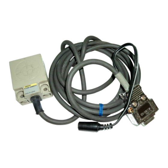
- Page 1 (1/30) V700 RFID System Model V700-HMD11 Reader Writer Operation Manual First Edition...
-
Page 2: Table Of Contents
(2/30) This manual describes the specifications and transmission format of the Model V700-HMD11 Reader Writer. Table of Contents 1. Product Outline................4 2. Specifications and Performance .............4 Shape ...............4 General Specifications ..........5 High-end Interface Specifications......6 3. Operations of the Reader Writer .............7 Outline of Operations.............7 Oscillation Control ................7 Memory Management on Tag ..........8... - Page 3 (3/30) Precautions of Use This Product uses a frequency of 125 kHz to communicate with a tag. Some transceivers, motors, monitor units, and power supply (power IC) emit noise that adversely affects this communication with the tag. If this product is to be used in an environment close to such devices, please check the effects from these devices prior to use.
-
Page 4: Product Outline
Model V700-HMD11 is an integrated unit of the transmission/reception circuit and control function, for communication with a Model V700 Series tag. This model is a small type reader/writer, which can be connected to higher end devices through an RS232 interface. -
Page 5: General Specifications
(5/30) General Specifications Item Specifications Remark Can be installed on Mounting method 2 points, secured by any metal board *. M4 screws 5V ± 5% Power supply Power is supplied from a dedicated AC adapter. Current consumption 200 mA or less (in oscillation) 25 mA or less (no oscillation) Insulation resistance 50 mΩ... -
Page 6: High-End Interface Specifications
(6/30) (3) High-end Interface Specifications Item Specifications Connector D-sub 9-pin connector, female (applies to DOS/V machines) Communication method RS232 compliant Synchronisation Asynchronous mode, start-stop synchronisation method method Communication control One to one procedure method Transmission speed 9600 bps (fixed) Character format Start bit Data bit Parity bit... -
Page 7: Operations Of The Reader Writer
(7/30) 3. Operations of the Reader Writer 3.1 Outline of Operations The Reader Writer receives commands from the High-end device, executes read / write processes on the Tag, and returns a response of the results of the process to the High-end device. The status of the Reader Writer operations will be reflected on the Output / LED. -
Page 8: Memory Management On Tag
(8/30) 3.3 Memory Management on Tag There are two types of the tag in the memory capacity: 128 bytes (user area 112 bytes) and 256 bytes (user area 240 bytes). The memory area recognises every 8 bytes as one page, distinguished by such addresses as 00h ~ 07h, 08h ~0Fh, and so on. -
Page 9: Processing Of Tag Memory
(9/30) 3.4 Processing of Tag Memory (1) Process Contents The following three processes are executed on the Tag Memory Data Read Reading data from Tag Memory in units of pages. The area to execute the Read command is selected at random up to 16 pages (CR control) / 28 pages (Number of characters control). -
Page 10: Transmission Operations
(10/30) (2) Transmission Operations The following 6 transmission operations are executed by changing the process procedure and execution timing. Transmission operations are specified by commands during command transmission. Single Trigger Transmission with Tag is executed immediately after receiving command and a response is transmitted. After response is transmitted, the Reader Writer will be on stand by for new commands. - Page 11 (11/30) FIFO Trigger The Reader Writer will communicate with Tag immediately after receiving command and transmit response. After transmission is completed, the Reader Writer will prohibit Tag from operating. The Reader Writer will be on stand by for commands after response is transmitted.
- Page 12 (12/30) FIFO Continue After waiting for the Tag to approach, then communicates with the Tag and transmits a response. After transmission is completed, Tag will become inoperative. After transmitting a response, the Reader Writer will await Tag to approach again if it receives [ACK], and CONTINUE UNTIL THE READER WRITER RECEIVES A STOP COMMAND.
-
Page 13: Controlling The Reader Writer From High-End Devices
(13/30) 4. Controlling the Reader Writer from High-end Devices 4.1 Communication Frame Frame format consists of 16 different types of data, “0” ~ “F,” in units of even- number characters and a terminator [CR] (ASCII Code: 0Dh). Data section: within 272 characters (in even numbers) Data 1 Data 2 . -
Page 14: Commands
(14/30) (1) Commands Specifies the process of the Reader Writer. The following commands are available. Command Numbe Description Name Read Reads Tag Memory data in unit of pages Write Writes data onto Tag Memory in unit of pages Multiple Write Writes the same data onto Tag Memory in unit of pages Byte Write Writes data onto Tag Memory in unit of bytes... -
Page 15: Completion Code
(15/30) (3) Completion Code The Reader Writer will return the response to the high-end unit by transmitting a completion code. The definitions of the completion codes are as follows: Class Completion Name Details Code Normal end Normal end Normal operations completed. ∗... -
Page 16: Commands Types And Responses
(16/30) 4.3 Commands Types and Responses (1) Read Read command is used when data is to be read from the Tag. Data for any specified page may be read. The maximum number of pages that may be read at one time is 16. n Command The pages to be read as parameters will be transmitted. -
Page 17: Write
(17/30) (2) Write The Write command is used when data is to be written onto the Tag Memory in units of pages. Data can be written on any specified page. The maximum number of pages onto which data may be written at one time is 16. n Command The pages to be written on, as parameters and the data to be written onto each page will be transmitted. -
Page 18: Multiple Write
(18/30) (3) Multiple Write The Multiple Write command is used when the same data is written in units of pages. Pages may be specified at random. There is no limit on the number of pages that may be written at one time. n Command The designated pages to be written as parameters and the data to be written onto each page is transmitted. -
Page 19: Byte Write
(19/30) (4) Byte Write The Byte Write command is used when data is to be written onto the Tag in unit of Bytes. Data of any bytes can be written from the specified address. An area spanning over more than one page may be specified, but a maximum limit of 16 pages applies. -
Page 20: Write Protection
(20/30) (5) Write Protection The Write Protection command is used to set or turn off write protection on Tag. n Command The pages to set or turn off write protection on as parameters will be transmitted. Page specifications shall be made by specifying the bit indicating the page as “1” and the other bytes as “0”. -
Page 21: Ack
(21/30) (6) ACK ACK is transmitted after receiving the response during FIFO Continue operation, and it allows reading of the following: n Command Command Terminator “1” “1” n Response There is no response. (7) NACK When the High-end device was not able to receive a response correctly, NACK is transmitted to demand the response to be transmitted again. -
Page 22: Oscillation On / Off
(22/30) (9) Oscillation ON / OFF The Oscillation ON / OFF command specifies the oscillation of the antenna. n Command Oscillation ON Oscillation OFF Command Terminator Command Terminator “1” “4” “1” “5” n Response Completion Code Terminator “0” “0” (10) Test The Test command is to conduct transmission tests on the communication to the High-end device. -
Page 23: Transmission Specification (Reference Values)
(23/30) 5. Transmission Specification (Reference Values) 5.1 Transmission Distance The transmission distance specifications are as follows. Please take note that transmission distance is subject to change, depending on installation requirements. Please refer to “6. The Influence of Requirements of Use on Transmission Distance.”... -
Page 24: Transmission Area
(24/30) 5.2 Transmission Area • Reader Writer: Model V700-HMD11 • Tag: Model V700-D13P31 / Model V700-D13P21 The transmission area diagram going through the center of the antenna and indicated on a flat surface vertical to the antenna surface is as indicated below. Read / write are the same area. -
Page 25: Communication Time
(25/30) 5.3 Communication Time The Model V700 Series has two communication times: the transmission time and the TAT (Turn Around Time). (1) Transmission Time This is the transmission processing time between the Reader Writer and the Tags. This time varies in accordance with the number of pages to be read / written. -
Page 26: The Influence Of Requirements Of Use On Transmission Distance (Reference Values)
(26/30) 6. The Influence of Requirements of Use on Transmission Distance (Reference Values) When using the Reader Writer, transmission distance varies in accordance with the requirements of use (the existence / non-existence of metal objects in the vicinity, the use /non-use of multiple Reader Writer, power voltage value, etc.). - Page 27 (27/30) n Metal Objects behind Reader Writer Model V700-HMD11 Distance away from metal X (mm)
-
Page 28: Mutual Interference Between Reader Writers
(28/30) 6.2 Mutual Interference between Reader Writers When using more than one Reader Writer, to prevent erroneous operations due to interference from other Reader Writers, please be sure to check that the below- indicated distance between Reader Writers is secured. n When Using Multiple Reader Writers in a Line 410mm or more 410mm or more... -
Page 29: Effects Of Antenna Angle
(29/30) 6.3 Effects of Antenna Angle Please install the Reader Writer and Tags so that they are parallel to each other whenever possible. The Reader Writer and Tags can communicate when installed on angles, but the transmission distance will be shorter. The relationship between angles and transmission distance is as indicated below. -
Page 30: Appendix 1 Document Revision History
(30/30) Appendix 1 Document Revision History Date Modification Contents Oct., 1998 First Edition... - Page 31 Buyer indemnifies Omron against all related costs or expenses. rights of another party. 10. Force Majeure. Omron shall not be liable for any delay or failure in delivery 16. Property; Confidentiality. Any intellectual property in the Products is the exclu-...
- Page 32 For US technical support or other inquiries: 800.556.6766 OMRON CANADA, INC. Milner Avenue Toronto, Ontario M 416.286.6465 OMRON ON-LINE Global - http://www.omron.com USA - http://www.omron.com/oei Canada - http://www.omron.ca V700HMDMAN 8/05 ©2005 OMRON ELECTRONICS LLC Specifications subject to change without notice. Printed in the U.S.A.