Table of Contents
Advertisement
Advertisement
Table of Contents

Related Manuals for Omron V700-D23P41


Summary of Contents for Omron V700-D23P41
- Page 1 SEMI STANDARD-COMPATIBLE CIDRW SYSTEM USER'S MANUAL CIDRW Controller Model V700-L21 ID Link Unit Model V700-L11 IDRW Head Model V700-HMD13 Model V700-HMD11-1 ID Tag Model V700-D23P41 OMRON Corporation © OMRON Corporation 2000 All Right Reserved Catalog No. Z214-E1-01B...
- Page 2 Introduction Thank you for purchasing the OMRON product. To be able to operate the product safely and efficiently, carefully study this user's manual and get fully familiar with the instruction in it before attempting to use the product. Keep this manual at hand for speedy reference...
- Page 3 Please read and understand this document before using the products. Please consult your OMRON representative if you have any questions or comments. WARRANTY OMRON’s exclusive warranty is that the products are free from defects in materials and workmanship for a period of one year (or other period if specified) from date of sale by OMRON. OMRON...
-
Page 4: Introduction
Introduction Meanings of Signal Words The following signal words are used in this manual. Indicates a potentially hazardous situation which, if not avoided, will result in minor or moderate injury, or may result in serious injury or death. Additionally, there may be WARNING significant property damage. -
Page 5: Precautions For Correct Use
Introduction Precautions for Correct Use To operate the CIDRW system more reliably and to allow the system to fully perform as designed, follow the instructions below: About environments of installation Do not install or leave the product to a location such as: •... -
Page 6: Limitations About Model V700-Hmd13
Introduction Limitations about Model V700-HMD13 When a Model V700-HMD13 (not Model V700-HMD13 ) is used to configure a CIDRW system, there will be the operating limitations described below. <Description of limitations> Data read (S18F5/F6) and data write (S18F7/F8) by single segments are possible only with data segments assigned to pages 1 through 12 within the memory page1 1 through 30 on an ID tag. -
Page 7: Table Of Contents
2.4.1 Names and functions of various components/specifications 2.4.2 Interface specifications (same as with Model V700-HMD13 ) 2.4.3 Dimensional drawing and mounting method 2.4.4 Communication performance (information only) 2.5 ID tag: Model V700-D23P41 2.5.1 Dimensional drawing and specifications 2.5.2 Memory map V700-L21... - Page 8 Introduction Section 3 System Connections 3.1 Connection work and startup 3.2 System configuration example Section 4 SECS Protocol Specifications 4.1 Operation model 4.2 Protocol specifications 4.3 Support attributes 4.4 Message specifications 4.5 Operating conditions Section 5 Setup Mode 5.1 Accessing setup mode 5.2 How to set up parameters Section 6 Reference 6.1 Processing Time (information only)
-
Page 9: Section 1 System Configuration And Features
Section 1 System Configuration and Features 1.1 System configuration 1.2 Features V700-L21 User's Manual... -
Page 10: System Configuration
Communications Standards, where SEMI stands for Semiconductor Equipment and Materials International), and which comprises Model V700-L21 CIDRW controller, Model V700-L11 ID link unit, Model V700-HMD13 or V700-HMD11-1 ID R/W head, and Model V700-D23P41 ID tag. The normative SECSs for the system include: •... -
Page 11: Features
Section 1 System Configuration and Features 1.2 Features OMRON's SEMI standard-conforming CIDRW system is configured with the following units: Model V700-L21 (CIDRW controller) This unit is linked with upstream equipment (upstream controller, etc.) in accordance with SECS I/II- compatible protocol and controls the CIDRW system. Being driven by a 24 VDC power supply, it is linked to one or more ID R/W heads via a link unit. - Page 12 SEMI standards. It is delivered together with two mounting nuts. Mounting nut (2 Model V700-D23P41 (ID tag) This is a round rod type ID tag that measures 3.9 mm in diameter and 25 mm in length. It contains a memory space of 240 bytes that allows a user to read or write data from or into it.
-
Page 13: Section 2 Unit Specifications
2.4.1 Names and functions of various components/specifications 2.4.2 Interface specifications (same as with Model V700-HMD13 ) 2.4.3 Dimensional drawing and mounting method 2.4.4 Communication performance (information only) 2.5 ID tag: Model V700-D23P41 2.5.1 Dimensional drawing and specifications 2.5.2 Memory map V700-L21 User's Manual... -
Page 14: Cidrw Controller: Model V700-L21
Section 2 Unit Specifications 2.1 CIDRW controller: Model V700-L21 2.1.1 Names and functions of various components/specifications POWER indicator STATUS indicators Mounting hole POWER OPERATING ALARMS STATUS BUSY ID port ERROR SECS port Maintenance port (w/ cover) SECS 24 V power supply terminal (with cover) 24 V power supply terminal (with cover) A power terminal and a GR (frame ground) terminal, for supplying 24 VDC. - Page 15 Section 2 Unit Specifications MODE switch RESET switch MODE RESET SECS MODE switch This is a 8-position rotary switch that selects an intended operation mode. Available operation modes are normal operation mode and setup mode. The controller is factory-set to normal operation mode MODE SW position Operation mode Function...
- Page 16 GR (frame ground) 6 mm max. 24 VDC • Recommended 24 V power supply: 6 mm max. Model S82K-03024 (OMRON) Wrong wiring connection can lead to a malfunction of the equipment. Be fully sure of the correct wiring connections. V700-L21 User's Manual...
-
Page 17: Interface Specifications
RS to CS(*2-1),the directionality of cable will be lost. • Recommended cable: CO-MA-VV-SB 5PX28AWG (Hitachi Cable, Ltd.) • Recommended connector: socket-Model XM2D-0901 (OMRON), hood-Model XM2S-0913 (OMRON) Wrong wiring connection can lead to a malfunction of the equipment. Be fully sure of the correct wiring connections. - Page 18 *1 Ground the shielded cable either on the CIDRW controller side or link unit side. • Recommended cable: CO-MA-VV-SB 5PX28AWG (Hitachi Cable, Ltd.) • Recommended connector: socket-Model XM2D-0901 (OMRON), hood-Model XM2S-0913 (OMRON) Wrong wiring connection can lead to a malfunction of the equipment. Be fully sure of the correct wiring connections.
-
Page 19: Dimensional Drawing And Mounting Method
Section 2 Unit Specifications 2.1.3 Dimensional drawing and mounting method Mounting holes (1: 2) POWER indicator 4-M4 STATUS indicators 4- 4.5 P6 3 (mounting holes) Case material Steel sheet (SPCC-P) (Unit: mm) Mounting method Install the controller using the four mounting holes and four M4 screws together with the enclosed washers. -
Page 20: Names And Functions Of Various Components/Specifications
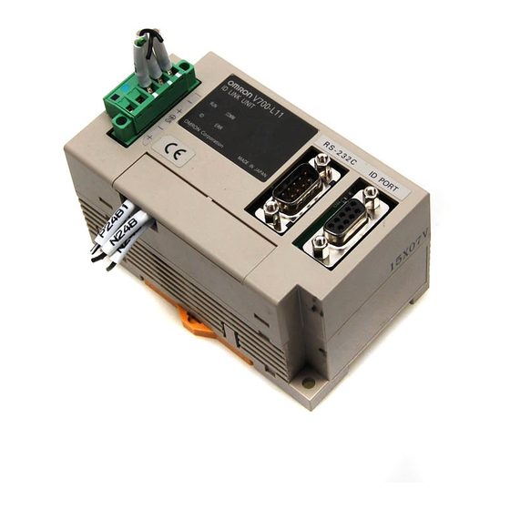
Section 2 Unit Specifications 2.2 Link unit: Model V700-L11 2.2.1 Names and functions of various components/specifications Multiconnection port (RS-485) Status indicators Upstream controller connection port (RS-232C) ID connection port Setup DIP-SW (behind cover) 24 V power terminals (behind cover) Upstream controller connection port (RS-232C) This port is for connection to the CIDRW controller according to RS-232C interface standard, and a dust cover has been factory-installed to it. - Page 21 RS-485 terminator ON/ OFF • Recommended 24 V power supply: Model S82K-03024 (OMRON) • Set the Baud rate on the link unit to that on the ID port of Model V700-L21 CIDRW controller. • Set the RS-485 terminator setting to ON for the link units on both ends of multidrop, and to OFF for other units.
- Page 22 Section 2 Unit Specifications • Assign a unique node No. to an IDRW head within a given subsystem. A node No. defined with this DIP-SW is taken as a "Head ID" (E99). [DIP-SW setting vs. Node No. correspondence table] Switch No. in setup DIP-SW Node No.
-
Page 23: Interface Specifications
*1 Ground the shielded cable either on the CIDRW controller side or link unit side. • Recommended cable: CO-MA-VV-SB 5PX28AWG (Hitachi Cable, Ltd.) • Recommended connector: socket-Model XM2D-0901 (OMRON), hood-Model XM2S-0913 (OMRON) Wrong wiring connection can lead to a malfunction of the equipment. Be fully sure of the correct wiring connections. - Page 24 Section 2 Unit Specifications (2) Multiconnection port Characteristic Specification Connector specification 5-pin special connector (built into the link unit) Communication standard RS-485 Baud rate 38400, 19200, 9600, 4800 bps (selectable with DIP-SW) Total cable length 50 m max. (Pin arrangement) Pin No.
- Page 25 An ordinary screwdriver whose shank is tapered at the tip does not go all the way into the hole. Use a miniature flat-blade screwdriver with a straight shank. Tighten the cable locking screws at an appropriated tightening torque (approx. 0.5 N-m). The following purpose-built screwdriver is available: OMRON: Model XW4Z-00C Form of tip Side view Front view...
-
Page 26: Dimensional Drawing And Mounting Method
Section 2 Unit Specifications 2.2.3 Dimensional drawing and mounting method RS-232C connector 41.3 41.5 20.3 ID port connector 35.2 4 Status indicators RS-485 connector Mounting holes 2-M4 OR Case material PC/ABS resin (Unit: mm) * Be sure to limit the tightening torque for the M4 screws to 1.2 N-m or less. Do not apply an organic solvent such as thread glue to the threads. -
Page 27: Idr/W Head: Model V700-Hmd13
Section 2 Unit Specifications 2.3 IDR/W head: Model V700-HMD13 2.3.1 Names and functions of various components/specifications Communication area Mounting bracket I/F connector I/F cable Antenna section Antenna section This section reads or writes data from or into an ID tag. Mounting bracket This bracket is for securing the antenna section. -
Page 28: Interface Specifications (Same As With Model V700-Hmd11-1)
M2.6 * For the 5 V/0 V power line, use a cable whose conductor size is AWG22 or greater. • Recommended cable:OTSC-8PVB-2 No. 22AWG (Onamba) • Recommended connector: <IDRWH side> socket-Model XM2D-0901 (OMRON), hood-Model XM2S-0911 (OMRON), lock-Model XM2Z-0001 (OMRON) <Link unit side> plug-Model XM2A-0901 (OMRON), hood-Model XM2S-0911(OMRON) Wrong wiring connection can lead to a malfunction of the equipment. -
Page 29: Dimensional Drawing And Mounting Method
Section 2 Unit Specifications 2.3.3 Dimensional drawing and mounting method IDR/W head with mounting brackets installed PVC-insulated round cable 6 (7/ 0.18) Coil 4-M4 8-core, standard length, 1 m (FOUP side) 119.8 149.8 Mounting bracket (material: SUS 304) Mounting bracket (material: SUS 304) 4-M4 22.4... - Page 30 Section 2 Unit Specifications Mounting brackets 2-M4 2-M4 10.1 10.1 44.8 44.8 36.4 36.4 Mounting hole dimensional drawing Mounting holes dimensions (top mounting configuration) Mounting holes dimensions (front mounting configuration) 4-M4 OR * Be sure to limit the tightening torque for the M4 screws and bracket mounting screws to 1.2 N-m or less.
-
Page 31: Communication Performance (Information Only)
Section 2 Unit Specifications 2.3.4 Communication performance (information only) Communication area (Model V700-HMD13 vs. Mode V700-D23P41) Locus of the tip of V700-D23P41 V700-D23P41 FOUP side Unit: mm Antenna Location of the tip of ID tag ID tag mounting position stipulated... -
Page 32: Idr/W Head: Model V700-Hmd11-1
Section 2 Unit Specifications 2.4 IDR/W head: Model V700-HMD11-1 2.4.1 Names and functions of various components/specifications Communication area I/F connector I/F cable Antenna section Status indicators (located on sideplate) Antenna section This section reads or writes data from or into an ID tag. I/F connector This interface connector supplies power to IDR/W head, and permits data transmission with an upstream controller. -
Page 33: Interface Specifications (Same As With Model V700-Hmd13 )
M2.6 * For the 5 V/0 V power line, use a cable whose conductor size is AWG22 or greater. • Recommended cable:OTSC-8PVB-2 No. 22AWG (Onamba) • Recommended connector: <IDRWH side> socket-Model XM2D-0901 (OMRON), hood-Model XM2S-0911 (OMRON), lock-Model XM2Z-0001 (OMRON) <Link unit side> plug-Model XM2A-0901 (OMRON), hood-Model XM2S-0911(OMRON) Wrong wiring connection can lead to a malfunction of the equipment. -
Page 34: Dimensional Drawing And Mounting Method
Section 2 Unit Specifications 2.4.3 Dimensional drawing and mounting method Model V700-HMD11-1 6, length 1000 Lock screw 4-R1 (mounting hole) 45.5 Status indicator Case material ABS resin (Unit: mm) Filler resin Epoxy resin Cable PVC (oil-resistant) Mounting method (1) Front mounting 2-M4 Center of coil (2) Back mounting... -
Page 35: Communication Performance (Information Only)
2.4.4 Communication performance (information only) Communication area (Model V700-HMD11-1 vs. Mode V700-D23P41) Recommended communication area Y (mm) 37mm Model V700-HMD11-1 X (mm) Effect of background metal (Model V700-HMD11-1 vs. Mode V700-D23P41) Model V700-HMD11-1 Distance to background metal X (mm) V700-L21 User's Manual... -
Page 36: Id Tag: Model V700-D23P41
Section 2 Unit Specifications 2.5 ID tag: Model V700-D23P41 2.5.1 Dimensional drawing and specifications General specifications Characteristic Specification Memory capacity 240 bytes (user area) Memory type EEP-ROM Data retention time 10 years after data writing Number of overwrites 100,000 times per address −25 to +70°C (no freezing) -
Page 37: Memory Map
Section 2 Unit Specifications 2.5.2 Memory map The carrier IDs and data segments are assigned to the following memory addresses in an ID tag. Page 8 bytes/page DATASEG LENGTH Carrier ID (16 byte) "S01" "S02" "S03" "S04" "S05" "S06" "S07" "S08"... - Page 38 Section 2 Unit Specifications MEMO V700-L21 User's Manual...
-
Page 39: Section 3 System Connections
Section3 System Connections 3.1 Connection work and startup 3.2 System configuration example V700-L21 User's Manual... -
Page 40: Connection Work And Startup
Section 3 System Connections 3.1 Connection work and startup Connect the CIDRW controller to an upstream controller (equipment controller, etc.) with an RS- 232C cable. The maximum allowable cable length is limited to 15 m. According to the intended CIDRW system configuration, choose the protocol parameters for the CIDRW controller and Baud rate for communications with the link unit. -
Page 41: System Configuration Example
Section 3 System Connections 3.2 System configuration example A typical example of a CIDRW controller connected to a plurality of heads is given below. Upstream controller Head Head Head Head "HeadID" "01" "HeadID" "02" "HeadID" "03" "HeadID" "N" 24 V 24 V 24 V 24 V... - Page 42 Section 3 System Connections MEMO V700-L21 User's Manual...
-
Page 43: Section 4 Secs Protocol Specifications
Section 4 SECS Protocol Specifications 4.1 Operation model 4.2 Protocol specifications 4.3 Support attributes 4.4 Message specifications 4.5 Operating conditions V700-L21 User's Manual... -
Page 44: Operation Model
Section 4 SECS Protocol Specifications 4.1 Operation model Set the MODE switch to 0 position, and power UP the CIDRW system. The CIDRW system is then initialized, and then acts according to the state models defined in SEMI E99. (1) CIDRW state model The system is running in operating mode. -
Page 45: Protocol Specifications
Section 4 SECS Protocol Specifications 4.2 Protocol specifications (1) Character structure Start bit (1) + data bits (8) + stop bit (1) *Per SEMI E4 (2) Protocol parameters Symbol Name Default Range Resolution 9600 1200,2400,4800,9600,19200, BAUD Baud rate 38400,57600,115200 bps DEVID Device ID 0 - 32767... - Page 46 Section 4 SECS Protocol Specifications (9) Handling of system bytes A system byte consists of a source ID and a transaction ID. A source ID is a fixed value and is specified in setup mode. The initial value of transaction ID is 1, and the maximum value is 0xFFFF. A transaction ID is incremented every time a primary message is transmitted.
-
Page 47: Support Attributes
Maintenance Data Supplier dependent 20 80byte Factory setting is " " (spaces) Manufacturer The name or ID of the 20 17byte manufacturer "OMRON Corporation" Model Number The manufacturer's 20 6byte model designation "L21 " (SerialNumber) Subsystem serial num- 20 max. 20 bytes... - Page 48 Section 4 SECS Protocol Specifications (2) Reader/Writer head attribute definitions Attribute name Description Access Requested Form Fundamental Head Status Current state "IDLE" "BUSY" "NOOP" Head ID Head number 1-31 (multi) "01"-"31" * "00" represents the CIDRW itself, and must not be used. Optional Cycles Number of read and...
-
Page 49: Message Specifications
Section 4 SECS Protocol Specifications 4.4 Message specifications (1) Message list Direction Name per SECS II S,H←E Abort transaction S,H→E,reply On line acknowledge request S,H←E On line data S,H→E Abort transaction S,H←E Unrecognized device ID S,H←E Unrecognized stream type S,H←E Unrecognized function type S,H←E Illegal data... - Page 50 Section 4 SECS Protocol Specifications (2) Data item dictionary SECS II data item Name Format Value ATTRID Attribute ID Attribute name ATTRVAL Attribute value Attribute value Carrier ID 20 (16 bytes fixed) All characters 00H-0FFH DATA Data 20 (8 bytes fixed) All characters 00H-0FFH DATALENGTH Data size...
- Page 51 Section 4 SECS Protocol Specifications (3) Stream/function specifications S1,F1 On line acknowledge request S,H→E,reply Header only S1,F2 On line data S,H←E 1.<MDLN> 2.<SOFTREV> • Defines an MDLN = Model Number. • Defines SOFTREV = Software Revision Level. V700-L21 User's Manual...
- Page 52 Section 4 SECS Protocol Specifications S18,F1 Read attribute request S,H→E,reply 1.<TARGETID> "00"-"31" 2.L,n 1.<ATTRID1> n.<ATTRIDn> • If all the attributes (CIDRW controller or head) are to be read, then set n=0. S18,F2 Read attribute data S,H←E 1.<TARGETID> "00"-"31" 2.<SSACK> 3.L,n 1.<ATTRVAL1>...
- Page 53 Section 4 SECS Protocol Specifications S18,F3 Write attribute request S,H→E,reply 1.<TARGETID> Fixed at "00" 2.L,n 1.L,2 1.<ATTRID1> 2.<ATTRVAL1> n.L,2 1.<ATTRIDn> 2.<ATTRVALn> • Since all the HEAD attributes with the CIDRW are R0, the TARGETID is fixed at "00". S18,F4 Write attribute acknowlegde S,H←E 1.<TARGETID>...
- Page 54 Section 4 SECS Protocol Specifications S18,F5 Read request S,H→E,reply 1.<TARGETID> "01"-"31" 2.<DATASEG> 3.<DATALENGTH> • If all the data of all segments are requested as a block, both DATASEG and DATALENGTH must be zero length items. • If all the data in a particular segment is requested, DATALENGTH alone is omitted (zero length item or zero). •...
- Page 55 Section 4 SECS Protocol Specifications S18,F7 Write data request S,H→E,reply 1.<TARGETID> "01"-"31" 2.<DATASEG> 3.<DATALENGTH> 4.<DATA> • If all the data of all segments are requested as a block, both DATASEG and DATALENGTH must be zero length items. • If all the data in a particular segment is requested, DATALENGTH alone is omitted (zero length item or zero). •...
- Page 56 Section 4 SECS Protocol Specifications S18,F9 Read ID request S,H→E,reply 1.<TARGETID> "01"-"31" S18,F10 Read ID data S,H←E 1.<TARGETID> "01"-"31" 2.<SSACK> 3.<MID> 4.L,s 1.<STATUS1> s.<STATUSs> • When the specified target is invalid: s=0, MID item length = 0, SSACK = CE (communications error) •...
- Page 57 Section 4 SECS Protocol Specifications S18,F11 Write ID request S,H→E,reply 1.<TARGETID> "01"-"31" 2.<MID> × • If an MID is defined which is shorter than the preset ID length, the data is written in a lower address, and the NULL (0 00) string is writ- ten as remaining data.
- Page 58 S,H→E,reply 1.<TARGETID> Fixed at "00" 2.<SSCMD> "Change State" 3.L,1 1.<CPVAL1> "OP", "MT", "PS" • CPVAL1="PS" is a parameter unique to OMRON CIDRW controller, and is used to access setup mode. S18,F14 Subsystem command acknowledge (ChangeState) S,H←E 1.<TARGETID> "00" 2.<SSACK> 3.L,s 1.<STATUS1>...
- Page 59 Section 4 SECS Protocol Specifications S18,F13 Subsystem command request (GetStatus) S,H→E,reply 1.<TARGETID> "00"-"31" 2.<SSCMD> "GetStatus" 3.L,0 S18,F14 Subsystem command acknowledge (GetState) S,H←E 1.<TARGETID> "00"-"31" 2.<SSACK> 3.L,s 1.<STATUS1> s.<STATUSs> • When the specified target is invalid: s=0, SSACK = CE (communications error) •...
- Page 60 Section 4 SECS Protocol Specifications S18,F13 Subsystem command request (PerformDiagnostics) S,H→E,reply 1.<TARGETID> "00"-"31" 2.<SSCMD> "Perform Diagnostics" 3.L,0 S18,F14 Subsystem command acknowledge (PerformDiagnostics) S,H←E 1.<TARGETID> "00"-"31" 2.<SSACK> 3.L,s 1.<STATUS1> s.<STATUSs> • When the specified target is invalid: s=0, SSACK = CE (communications error) •...
- Page 61 Section 4 SECS Protocol Specifications S18,F13 Subsystem command request (Reset) S,H→E,reply 1.<TARGETID> Fixed at "00" 2.<SSCMD> "Reset" 3.L,0 S18,F14 Subsystem command acknowledge (Reset) S,H←E 1.<TARGETID> "00" 2.<SSACK> 3.L,0 • When the specified target is invalid: s=0, SSACK = CE (communications error) •...
-
Page 62: Operating Conditions
Section 4 SECS Protocol Specifications 4.5 Operating conditions The acknowledge messages and acknowledge codes (SSACK) for various states are listed below: State Operating Initializing Maintenance Message Function IDLE BUSY S1,F1 Online Request S1,F0 S1,F2 S1,F2 S1,F2 S18,F11 Write ID S18,F0 S18,F0 S18,F0 S18,F7... -
Page 63: Section 5 Setup Mode
Section 5 Setup Mode 5.1 Accessing setup mode 5.2 How to set up parameters V700-L21 User's Manual... -
Page 64: Accessing Setup Mode
9-pin 9-pin female female #4-40 #4-40 • Recommended cable: CO-MA-VV-SB 5PX28AWG (Hitachi Cable, Ltd.) • Recommended connector: socket-Model XM2D-0901 (OMRON), hood-Model XM2S-0913 (OMRON) In the setup mode, the STATUS indicators will function as listed below: Status OPERATING ALARMS BUSY ERROR... -
Page 65: How To Set Up Parameters
Section 5 Setup Mode 5.2 How to set up parameters Various parameters are set up using a terminal software loaded into an upstream controller (PC/AT) connected to the SECS port of CIDWR controller. The communications parameters for data transaction between the upstream controller and CIDRW controller are fixed and cannot be altered on the CIDWR controller side. - Page 66 Section 5 Setup Mode To set up a parameter, send the following instructions from the terminal software. Instruction Format Action Parameter definition "(Tag name)" + "=" + "(setting value)" + CR + LF Enter the parameter for the tag name. Parameter change "::END"...
- Page 67 Section 5 Setup Mode [Parameter setup example] Link the CIDRW controller to the upstream controller, and boot up the terminal software. Then, power UP the CIDRW controller in setup mode.CIDRW SETUP_START <L21 ><XXX.XX,YYY.YY> For a parameter being altered, execute parameter definition. SETUP_START <L21 ><XXX.XX,YYY.YY>...
- Page 68 Section 5 Setup Mode [Parameter check example] Select a parameter output being altered. SETUP_START <L21 ><XXX.XX,YYY.YY> ::GET_PARAM [ENTER] * [ENTER] does not appear on the screen. The contents of the current parameter settings will be displayed. SETUP_START <L21 ><XXX.XX,YYY.YY> ::GET_PARAM S_BAUD=19200 S_DEVID=1 S_T1=0.5...
-
Page 69: Section 6 Reference
Section 6 Reference 6.1 Processing Time (information only) 6.2 Performance Data Based on Operating Conditions (information only) 6.2.1 Effect of nearby metal object onto IDRW head 6.2.2 Spacing for installing IDRW heads 6.2.3 Effect of inclination of ID tag V700-L21 User's Manual... -
Page 70: Processing Time (Information Only)
Reference 6.1 Processing Time (information only) As illustrated below, the processing time with OMRON CIDRW system begins with the trailing end of a request message sent from the upstream controller to the CIDWR controller and lasts until the CIDRW controller sends a request send (ENQ) to the upstream controller. -
Page 71: Performance Data Based On Operating Conditions (Information Only)
Section 6 Reference 6.2 Performance Data Based on Operating Conditions (information only) The maximum effective communication distance of an IDRW head varies depending on the operating conditions (presence/absence of a nearby metal object, spacing between the IDRW heads, etc.). This section describes the effect of varying operating conditions on the effective communication distance. -
Page 72: Spacing For Installing Idrw Heads
Section 6 Reference 6.2.2 Spacing for installing IDRW heads When two or more IDRW heads are connected to one CIDRW controller unit, there is no limitation on the spacing of antenna sections since all the IDRW heads do not handle a command simultaneously. If IDRW heads in an individual CIDRW system are installed in close vicinity, and when these IDRW heads are simultaneously processing a command, mutual interference can occur across the IDRW heads, possibly leading to total inability of communication or loss in effective communication distance despite presence of... -
Page 73: Effect Of Inclination Of Id Tag
However, in this situation, a shorter communication distance will result. The correlation between inclination and effective communication distance is summarized below. Model V700-HMD13 ID tag: V700-D23P41 Communication distance (value with zero inclination is taken as 100%) Inclination of ID tag θ (degrees) θ... - Page 74 Section 6 Reference MEMO V700-L21 User's Manual...
-
Page 75: Section 7 Troubleshooting
Section 7 Troubleshooting 7.1 No acknowledge message (Acknowledge message not yet received) 7.2 Acknowledge message received (other than SSACK="NO") V700-L21 User's Manual... -
Page 76: No Acknowledge Message (Acknowledge Message Not Yet Received)
Section 7 Troubleshooting If a fault should occur, first thoroughly study the symptom in order to be able to correctly judge the reproducibility of a problem, and interaction with other associated equipment. Thus, find an appropriate remedy. 7.1 No acknowledge message (Acknowledge message not yet received) State of indicators ( : lit,... -
Page 77: Acknowledge Message Received (Other Than Ssack="No")
Section 7 Troubleshooting 7.2 Acknowledge message received (other than SSACK="NO") Acknowledge Typical checkpoint S×F0 • Status conditions at the time a message was issued. Ex.: Write ID (S18F11) in Operating mode, or a message during initializing S9F7 • Problematic message structure such as illegal attribute, excessive/insufficient items SSACK="CE"... - Page 78 Section 7 Troubleshooting MEMO V700-L21 User's Manual...
-
Page 79: Revision History
Revision History A manual revision code is suffixed to the manual ID located to the bottom right corner of front cover and to the bottom left corner of back cover. Catalog No. Z214-E1-01B Revision code Revision note Data Revised contents September 2000 version Warranty and liability information added to beginning of manual, signal word and... - Page 80 OMRON ASIA PACIFIC PTE. LTD. 83 Clemenceau Avenue, #11-01, UE Square, 239920 Singapore Tel: (65)6835-3011/Fax: (65)6835-2711 OMRON CHINA CO., LTD. BEIJING OFFICE Room 1028, Office Building, Beijing Capital Times Square, No. 88 West Chang'an Road, Beijing, 100031 China Tel: (86)10-8391-3005/Fax: (86)10-8391-3688 Cat.