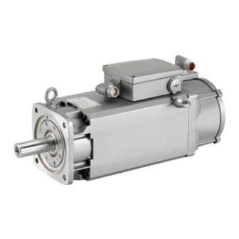
Siemens SIMOTICS M-1PH8 Operating Instructions & Installation Instructions
Induction motor
Hide thumbs
Also See for SIMOTICS M-1PH8:
- Configuration manual (266 pages) ,
- Operating instructions manual (186 pages) ,
- Manual (138 pages)

Related Manuals for Siemens SIMOTICS M-1PH8


Summary of Contents for Siemens SIMOTICS M-1PH8
- Page 1 Induction motor SIMOTICS M-1PH8 Type 1PH818., 1PH822. forced ventilated II 3D Ex tc IIIB T150°C Dc Operating Instructions / Installation Instructions 05/2012...
- Page 2 29.05.2012 13:11...
- Page 3 Introduction Safety notes Description Induction motor Preparations for use SIMOTICS M-1PH8 1PH8 Assembling Electrical connection Operating Instructions Installation Instructions Commissioning Operation Maintenance Spare parts Disposal Service and Support For employment in zone 22 (IEC/EN 60079-10-2) Quality documents II 3D Ex tc IIIB T150°C Dc...
-
Page 4: Edition
Note the following: WARNING Siemens products may only be used for the applications described in the catalog and in the relevant technical documentation. If products and components from other manufacturers are used, these must be recommended or approved by Siemens. Proper transport, storage, installation, assembly, commissioning, operation and maintenance are required to ensure that the products operate safely and without any problems. -
Page 5: Table Of Contents
Lifting and transporting........................35 4.11.4 Transporting a force-ventilated motor that has already been in operation........37 4.11.5 Transporting the machine set......................37 4.11.6 Storage............................38 4.11.7 Attaching the rotor locking device prior to storage..............39 4.11.8 Long-term storage........................40 SIMOTICS M-1PH8 Operating Instructions 05/2012 A5E03986435A AA... - Page 6 6.4.9 Converter operation on a grounded network................72 6.4.10 Connect metal shield in the terminal box ..................72 Commissioning............................73 Insulation resistance and polarization index................73 Checks to be carried out prior to commissioning ................73 Switching on..........................75 SIMOTICS M-1PH8 Operating Instructions 05/2012 A5E03986435A AA...
- Page 7 Removing and installing the protecting ring................105 9.4.5 Removing and mounting the bearing shields................106 9.4.6 Installing the machine........................106 9.4.7 Removing the external fan......................107 9.4.8 Removing and mounting the speed encoder................107 9.4.9 Touch up any damaged paintwork....................108 SIMOTICS M-1PH8 Operating Instructions 05/2012 A5E03986435A AA...
- Page 8 Introduction..........................121 11.2 Preparing for disassembly......................121 11.3 Dismantling the machine......................121 11.4 Disposal of components......................122 Service and Support..........................123 Siemens Service Center......................123 Quality documents............................125 EC Declaration of Conformity 2006/95/EC................127 EC Declaration of Conformity (Ex t)..................129 Additional documents..........................143 Operating instructions, external fan...................144 Index.................................153 Tables Table 3-1 Elements on the rating plate......................22...
- Page 9 Figure 4-3 Rotor shipping brace........................36 Figure 4-4 Schematic representation of a single drive..................42 Figure 5-1 Max. permissible vibration velocity, taking into account the vibration displacement and vibration acceleration..........................50 Figure 5-2 Aligning the machine........................51 SIMOTICS M-1PH8 Operating Instructions 05/2012 A5E03986435A AA...
-
Page 10: Spare Parts
Rolling-contact bearing bush drive end, with coupling output, with permanent lubrication..116 Figure 10-7 Roller bearing cartridge, non-drive end, permanent lubrication ..........117 Figure 10-8 Roller bearing cartridge NDE, with regreasing (type 1PH818., 1PH822.).........118 Figure 10-9 Terminal box..........................119 Figure 10-10 Speed encoder..........................120 SIMOTICS M-1PH8 Operating Instructions 05/2012 A5E03986435A AA... -
Page 11: Introduction
– Lists on the second level are hyphenated. Note A Note is an important item of information about the product, handling of the product or the relevant section of the document. Notes provide you with help or further suggestions/ideas. SIMOTICS M-1PH8 Operating Instructions 05/2012 A5E03986435A AA... - Page 12 Introduction 1.1 Content SIMOTICS M-1PH8 Operating Instructions 05/2012 A5E03986435A AA...
-
Page 13: Safety Notes
("Working in a voltage-free state). Apply the five safety rules in the order stated before starting work at the machine. Five safety rules 1. Disconnect the system. Disconnect the auxiliary circuits, for example anti-condensation heating 2. Prevent reconnection. 3. Make sure that the equipment is at zero voltage SIMOTICS M-1PH8 Operating Instructions 05/2012 A5E03986435A AA... -
Page 14: Qualified Personnel
● Always observe the "five safety rules (Page 13)" when carrying out any work on the machine. ● Only remove the covers using the methods described by these operating instructions. ● Operate the machine properly. ● Regularly and correctly maintain the machine. SIMOTICS M-1PH8 Operating Instructions 05/2012 A5E03986435A AA... - Page 15 Burns and other damage to health and material may result. ● Read the information in these operating instructions and the product information supplied by the manufacturer. ● Observe the relevant safety regulations and wear the personal protective equipment specified. SIMOTICS M-1PH8 Operating Instructions 05/2012 A5E03986435A AA...
-
Page 16: For Use In Hazardous Areas In Zone 22
The basic requirements relating to the assessment of ignition hazards arising from electrical systems and their operation in hazardous areas are given, for instance, in Directives 94/9/ EG and 1999/92/EG as well as in the series of standards IEC / EN 60079. SIMOTICS M-1PH8 Operating Instructions 05/2012 A5E03986435A AA... -
Page 17: Electrostatic Sensitive Devices
(1) Sitting (2) Standing (3) Standing/sitting a = conductive floor surface b = ESD table c = ESD shoes d = ESD overall e = ESD wristband f = cabinet ground connection SIMOTICS M-1PH8 Operating Instructions 05/2012 A5E03986435A AA... -
Page 18: Electromagnetic Compatibility
In order to avoid exceeding the limit values set in IEC/EN 61000-6-3 for the drive system (motor and converter), the EMC information provided by the converter manufacturer must be observed. You must put appropriate EMC measures in place. SIMOTICS M-1PH8 Operating Instructions 05/2012 A5E03986435A AA... -
Page 19: Electromagnetic Fields When Operating Electrical Power Engineering Installations
● Observe the nationally applicable health and safety regulations. ● Do not carry any magnetic or electronic data media with you. SIMOTICS M-1PH8 Operating Instructions 05/2012 A5E03986435A AA... - Page 20 Safety notes 2.10 Electromagnetic fields when operating electrical power engineering installations SIMOTICS M-1PH8 Operating Instructions 05/2012 A5E03986435A AA...
-
Page 21: Description
Never operate this machine in the above mentioned areas. Rating plate The rating plate shows the identification data and the most important technical data. The data on the rating plate and the contractual agreements define the limits of proper usage. SIMOTICS M-1PH8 Operating Instructions 05/2012 A5E03986435A AA... -
Page 22: Table 3-1 Elements On The Rating Plate
Operating mode (1) Maximum torque M Code for operating point 1 Maximum speed n Rated voltage V Temperature sensor Switching mode 2 Tachometer/resolver Rated current I Cooling method Rated power P Throughput l/min (m SIMOTICS M-1PH8 Operating Instructions 05/2012 A5E03986435A AA... -
Page 23: Table 3-2 Machine Design
The following standards additionally apply for explosion-proof motors: Table 3-3 Motor version with type of explosion protection Ex t Feature Standard Type of protection Ex t IEC / EN 60079-0 ① IEC / EN 60079-31 Optional (depending on order) ① SIMOTICS M-1PH8 Operating Instructions 05/2012 A5E03986435A AA... - Page 24 Vario eye bolts. The Vario eyebolts are in the terminal box. CAUTION Protection against falling parts For vertical types of construction, protect the air intake or discharge against falling parts, e.g. by attaching a canopy. Otherwise the machine could be damaged. SIMOTICS M-1PH8 Operating Instructions 05/2012 A5E03986435A AA...
- Page 25 The use in IT systems is not permitted. CAUTION The external fan may not be cleaned with a water jet. This results in material damage. Degree of protection The machine is available with degree of protection IP55. SIMOTICS M-1PH8 Operating Instructions 05/2012 A5E03986435A AA...
-
Page 26: Table 3-4 Roller Bearing Versions
Operating cylindrical roller bearings without a load can damage them. Maintain the minimum radial forces specified when using cylindrical-roller bearings. Table 3-5 Minimum radial forces Type Minimum radial force 1PH818. 4 kN 1PH822. 5 kN 1PH828. 9 kN SIMOTICS M-1PH8 Operating Instructions 05/2012 A5E03986435A AA... - Page 27 Description Paint finish The machine is painted according to the instructions in your order. SIMOTICS M-1PH8 Operating Instructions 05/2012 A5E03986435A AA...
- Page 28 Description SIMOTICS M-1PH8 Operating Instructions 05/2012 A5E03986435A AA...
-
Page 29: Preparations For Use
Higher requirements regarding the IP degree of protection may necessitate the installation of suitable filters and special arrangement of the intake and outlet openings. ● Equipment and cables must be connected without strain. SIMOTICS M-1PH8 Operating Instructions 05/2012 A5E03986435A AA... -
Page 30: Table 4-1 Pressure Drop In Motors With Pipe Connection
Table 4-1 Pressure drop in motors with pipe connection Type Volume flow Pressure drop Flow resistance 1PH818. 0,17 m 550 Pa 19030 Ns 1PH822. 0,31 m 650 Pa 6760 Ns SIMOTICS M-1PH8 Operating Instructions 05/2012 A5E03986435A AA... -
Page 31: Cooling Air Quality
The machine is equipped as standard with a KTY 84 temperature sensor, optionally with PTC thermistors to directly monitor the motor temperature to protect the machine against overload in operation. Plan a corresponding circuit for monitoring. See also Connecting the temperature sensor (Page 71) SIMOTICS M-1PH8 Operating Instructions 05/2012 A5E03986435A AA... -
Page 32: Overheating During Periodic Duty
Excessive rotational speed can lead to serious damage to the machine. This can result in death, serious injury, or material damage. The controller must ensure that operation at impermissible speeds is prevented. Observe the information about the speeds on the rating plate. SIMOTICS M-1PH8 Operating Instructions 05/2012 A5E03986435A AA... -
Page 33: System-Inherent Frequencies
Transport and storage When carrying out any work on the machine, observe the general safety instructions and the specifications contained in DIN EN 50110‑1 as regards working safely with and on electrical machines. SIMOTICS M-1PH8 Operating Instructions 05/2012 A5E03986435A AA... -
Page 34: Checking The Delivery
The drive systems are put together on an individual basis. When you take receipt of the delivery, please check immediately whether the items delivered are in accordance with the accompanying documents. Siemens will not accept any claims relating to items missing from the delivery and which are submitted at a later date. -
Page 35: Lifting And Transporting
● Pay attention to the lifting capacity of the hoisting gear. The weight of the motor is specified on the rating plate. Figure 4-2 Lifting the machine (schematic representation) SIMOTICS M-1PH8 Operating Instructions 05/2012 A5E03986435A AA... -
Page 36: Table 4-2 Tightening Torque For Rotor Shipping Brace
Rotor shipping brace Table 4-2 Tightening torque for rotor shipping brace Type Thread in the shaft end Tightening torque Preload 1PH818. 50 Nm 12 kN 1PH822. 50 Nm 12 kN 1PH828. 100 Nm 20 kN SIMOTICS M-1PH8 Operating Instructions 05/2012 A5E03986435A AA... -
Page 37: Transporting A Force-Ventilated Motor That Has Already Been In Operation
If the lifting gear or load handling attachments were to fail, the machine could fall. This can result in death, serious injury, or material damage. Never remain under the machine when it is raised. SIMOTICS M-1PH8 Operating Instructions 05/2012 A5E03986435A AA... -
Page 38: Storage
● Protect the motor from shocks and humidity. ● Cover the motor properly. ● Avoid contact corrosion: – Every three months, remove the shipping brace and rotate the shaft end by hand. – Then reattach the rotor shipping brace. SIMOTICS M-1PH8 Operating Instructions 05/2012 A5E03986435A AA... -
Page 39: Attaching The Rotor Locking Device Prior To Storage
On machines that have been supplied with a rotor shipping brace, secure the rotor as per the notes on transportation. Protect the machine against strong radial vibrations, since the rotor shipping brace might not absorb these completely. SIMOTICS M-1PH8 Operating Instructions 05/2012 A5E03986435A AA... -
Page 40: Long-Term Storage
Damage caused by condensation If the stator winding is damp, its insulation resistance is reduced. This results in voltage flashovers that can destroy the winding. Condensation can also cause rusting inside the machine. SIMOTICS M-1PH8 Operating Instructions 05/2012 A5E03986435A AA... -
Page 41: Protection Against Corrosion
● To ensure effective discharge of high-frequency currents, make the shield contact over the largest possible area, i.e. as a 360° contact on the converter and motor, e.g. using EMC glands at the cable entry points. SIMOTICS M-1PH8 Operating Instructions 05/2012 A5E03986435A AA... -
Page 42: Insulated Bearings For Converter Operation
● Use iron cores mounted above the motor connecting cable at the converter output. These help to reduce common-mode components. The Siemens sales representative is responsible for selection and dimensioning. ● Limit the voltage rate of rise by using an output filter to dampen harmonic components in the output voltage 4.12.2... -
Page 43: Operation With Insulated Coupling
If you connect two motors in series in "tandem operation", fit a coupling between the motors; this coupling should satisfy Directive 94/9/EC or the regulations that apply in the country where the equipment is installed.. SIMOTICS M-1PH8 Operating Instructions 05/2012 A5E03986435A AA... - Page 44 Preparations for use 4.12 Converter operation SIMOTICS M-1PH8 Operating Instructions 05/2012 A5E03986435A AA...
-
Page 45: Assembling
Measuring the insulation resistance and polarization index (PI) provides information on the condition of the machine. It is therefore important to check the insulation resistance and the polarization index at the following times: SIMOTICS M-1PH8 Operating Instructions 05/2012 A5E03986435A AA... -
Page 46: Testing The Insulation Resistance And Polarization Index
1. Before you begin measuring the insulation resistance, please read the manual for the insulation resistance meter you are going to use. 2. Disconnect any connected main-circuit cables from the terminals before measuring the insulation resistance. SIMOTICS M-1PH8 Operating Instructions 05/2012 A5E03986435A AA... -
Page 47: Table 5-1 Stator Winding Insulation Resistance At
= critical insulation resistance during operation at 40°C C, operation = insulation resistance converted to current measuring/winding temperature PI = polarization index R (T < 40°C) insul 10 min insul 1 min. T = current measuring/winding temperature SIMOTICS M-1PH8 Operating Instructions 05/2012 A5E03986435A AA... -
Page 48: Preconditions For Correct Alignment And Secure Attachment
If the critical insulation resistance is reached or undershot, this can damage the insulation and cause voltage flashovers. ● Contact your Siemens Service Center. ● If the measured value is close to the critical value, you must subsequently check the insulation resistance at shorter intervals. -
Page 49: Vibration Severity
Vibration velocity v ≤ 7.1 mm/s > 63 Hz Vibration acceleration a ≤ 4.0 m/s Table 5-3 Maximum permitted axial vibration severity Vibration velocity Vibration acceleration = 7.1 mm/s = 3.55 m/s peak SIMOTICS M-1PH8 Operating Instructions 05/2012 A5E03986435A AA... -
Page 50: Aligning The Machine
● When positioning the motor, ensure that a uniform axial gap is maintained around the coupling. Note Alignment accuracy Remember to take account of data concerning the alignment accuracy of the driven load and the coupling. SIMOTICS M-1PH8 Operating Instructions 05/2012 A5E03986435A AA... -
Page 51: Securing The Machine
The number of shims should be kept as low as possible i.e. stack as few as possible. ● Select foot screws as per ISO 898-1 in compliance with the loading conditions and machine type: SIMOTICS M-1PH8 Operating Instructions 05/2012 A5E03986435A AA... -
Page 52: Tightening Torques For Screw And Bolt Connections
The bolted connections with metal contact surfaces, such as end shields, bearing cartridge parts, terminal box parts bolted onto the stator frame, should be tightened to the following torques, depending on the thread size: SIMOTICS M-1PH8 Operating Instructions 05/2012 A5E03986435A AA... -
Page 53: Mounting The Output Elements
● "H" means balancing with a half feather key ● "F" means balancing with a whole feather key. Figure 5-3 Balancing type on the drive-end side SIMOTICS M-1PH8 Operating Instructions 05/2012 A5E03986435A AA... - Page 54 ● Do not operate the machine unless the transmission elements have been pulled on. ● On shaft extensions without output element, make sure that the feather key cannot fall out and shorten it by approximately half for balance type "H". SIMOTICS M-1PH8 Operating Instructions 05/2012 A5E03986435A AA...
- Page 55 5.8 Mounting the output elements Note Type of balancing In the case of shaft extensions with feather keys, the type of balancing is also included on the rating plate next to the CE mark. SIMOTICS M-1PH8 Operating Instructions 05/2012 A5E03986435A AA...
- Page 56 Assembling 5.8 Mounting the output elements SIMOTICS M-1PH8 Operating Instructions 05/2012 A5E03986435A AA...
-
Page 57: Electrical Connection
● Tighten the screwed connections to the specified tightening torques. ● Observe any specifications regarding the materials from which fixing elements must be made. ● When performing servicing, check the fastenings. See also Tightening torques for screw and bolt connections (Page 52) SIMOTICS M-1PH8 Operating Instructions 05/2012 A5E03986435A AA... -
Page 58: Preparation
● When making connections, ensure the following: – the connecting surface is bare and protected against corrosion using a suitable substance, e.g. acid-free Vaseline – the flat and spring washers are located under the bolt head. SIMOTICS M-1PH8 Operating Instructions 05/2012 A5E03986435A AA... -
Page 59: Connecting
● Arrange the exposed connecting cables in the terminal box such that the PE conductor has excess length and the insulation of the cable strands cannot be damaged. SIMOTICS M-1PH8 Operating Instructions 05/2012 A5E03986435A AA... -
Page 60: Electrical Connection Data
Cable entry and technical connection data depend on the mounted terminal box. You can find more information on the terminal box that is mounted in the ordering documentation or in the catalog. 1XB7 322 1XB7 422 SIMOTICS M-1PH8 Operating Instructions 05/2012 A5E03986435A AA... -
Page 61: Connection With Cable Lugs
20 mm creepage distance, which are normally available. The tightening torque for contact nuts and fixing screws depends on the size of the screw, see Case A in the table in ChapterTightening torques for screw and bolt connections (Page 52). SIMOTICS M-1PH8 Operating Instructions 05/2012 A5E03986435A AA... - Page 62 Connection with cable lug at the terminal box 1XB7 700 / 1XB7 712 Note Terminal box 1XB7 712 is not used in hazardous areas of Zone 22. ① Customer connecting cable ② Connection bar See also Electrical connection data (Page 60) SIMOTICS M-1PH8 Operating Instructions 05/2012 A5E03986435A AA...
-
Page 63: Connecting Aluminum Conductors
Retighten the clamping nuts after approximately 24 hours and then again after approximately four weeks. Make sure that the terminals are de-energized before you tighten the nuts. SIMOTICS M-1PH8 Operating Instructions 05/2012 A5E03986435A AA... -
Page 64: Completing Connection Work
Connecting points are provided on the enclosure or end shield to allow an outer PE conductor or equipotential bonding conductor to be connected; see "Connecting the grounding conductor". See also Connecting the grounding conductor (Page 58) SIMOTICS M-1PH8 Operating Instructions 05/2012 A5E03986435A AA... -
Page 65: Auxiliary Circuits
This can otherwise result in damage. Ensure that you also observe the additional requirements in IEC / EN 60079‑14 for intrinsically safe equipment and the associated connecting cables. SIMOTICS M-1PH8 Operating Instructions 05/2012 A5E03986435A AA... -
Page 66: Connecting An External Fan
3. Connect the other cables to the relevant terminals, refer to the connection diagram. Connection cables must not be subject to excessive tensile stress. Note For fans equipped with EC motor, the fan motor starts with a delay after the line voltage is connected. SIMOTICS M-1PH8 Operating Instructions 05/2012 A5E03986435A AA... - Page 67 Operating instructions, external fan (Page 144) Connecting an external fan (type 1PH818., 1PH822.) The external fan is connected in the external fan terminal box. If necessary, you can rotate the external fan through 90°. SIMOTICS M-1PH8 Operating Instructions 05/2012 A5E03986435A AA...
-
Page 68: Connecting The Speed Encoder
The speed encoder is connected at the terminal box using a plug connection . This is located ② on the terminal box enclosure. A protective tube for disassembly is supplied as special fastener when removing the signal connector. SIMOTICS M-1PH8 Operating Instructions 05/2012 A5E03986435A AA... - Page 69 You can damage the sensor module if you turn it with a pipe wrench, a hammer, or similar tools. Turn the sensor module by hand. The typical torque is approx. 4 ... 8 Nm. ① Figure 6-5 Sensor Module mounted on the terminal box SIMOTICS M-1PH8 Operating Instructions 05/2012 A5E03986435A AA...
-
Page 70: Attach A Protective Tube For The Signal Connector
Operation without special fastener is not permissible. Figure 6-6 Slide the protective tube to remove the signal connector over the signal connector Figure 6-7 Screw the protective tube to remove the connector to the end position SIMOTICS M-1PH8 Operating Instructions 05/2012 A5E03986435A AA... -
Page 71: Connecting The Temperature Sensor
● Use iron cores mounted above the motor connecting cable at the converter output. These help to reduce common-mode components. The Siemens sales representative is responsible for selection and dimensioning. ● Limit the voltage rate of rise by using an output filter to dampen harmonic components in... -
Page 72: Converter Operation On A Grounded Network
If the metal shield is grounded more than once, it may form an electrical loop. In an explosive atmosphere, there is a risk of an explosion. This can result in death, serious injury or material damage. Ground the metal shield only once. SIMOTICS M-1PH8 Operating Instructions 05/2012 A5E03986435A AA... -
Page 73: Commissioning
The following list of checks to be performed prior to commissioning does not claim to be complete. It may be necessary to perform further checks and tests in accordance with the specific situation on-site. SIMOTICS M-1PH8 Operating Instructions 05/2012 A5E03986435A AA... - Page 74 ● The converter is correctly parameterized. The parameterization data is specified on the rating plate of the machine. Information about the parameters is available in the operating instructions for the converter. SIMOTICS M-1PH8 Operating Instructions 05/2012 A5E03986435A AA...
-
Page 75: Switching On
Maximum speed The maximum rotational speed n is the highest permissible operating speed. The maximum rotational speed is specified on the rating plate. SIMOTICS M-1PH8 Operating Instructions 05/2012 A5E03986435A AA... -
Page 76: Trial Run
DIN ISO 10816-3, as otherwise the motor could be damaged or destroyed. ● Monitor and log the temperatures of the bearings, windings, etc., until the system reaches the steady state, in as much as this is possible with the available measuring equipment. SIMOTICS M-1PH8 Operating Instructions 05/2012 A5E03986435A AA... -
Page 77: Operation
● Check the temperature of the parts before touching them and take appropriate protective measures if necessary. ● Allow the machine to cool down before starting work on the machine. SIMOTICS M-1PH8 Operating Instructions 05/2012 A5E03986435A AA... -
Page 78: Machine Overheating Caused By Dust
● In addition to the current-dependent overload protection device located in the three phases of the connecting cable, we recommend that you also monitor the temperature rise in the motor with the aid of the temperature sensors built into the stator winding. SIMOTICS M-1PH8 Operating Instructions 05/2012 A5E03986435A AA... -
Page 79: Operation
If a motor is operated at impermissible speeds damage to the winding, bearings, or complete destruction of the motor can be the result. Ensure that the speeds specified on the rating plate are not exceeded by appropriately configuring controller and speed monitoring components. SIMOTICS M-1PH8 Operating Instructions 05/2012 A5E03986435A AA... -
Page 80: Switching-Off Force-Ventilated Motors
When recommissioning the motor after a long period out of service, carry out the measures recommended in the chapter entitled "Commissioning (Page 73)". SIMOTICS M-1PH8 Operating Instructions 05/2012 A5E03986435A AA... -
Page 81: Avoidance Of Damage To Roller Bearings During Stoppages
If the machine is going to be out of service for longer than six months, then perform the necessary measures for anti-corrosion protection, preservation, packaging and drying. Otherwise damage to the machine will result. SIMOTICS M-1PH8 Operating Instructions 05/2012 A5E03986435A AA... -
Page 82: Re-Commissioning The Machine
8.9.2 Electrical faults at force-ventilated motors Note When operating the machine with a converter, also refer to the operating instructions of the frequency converter if electrical faults occur. SIMOTICS M-1PH8 Operating Instructions 05/2012 A5E03986435A AA... -
Page 83: Mechanical Faults
Resonance with the foundation Stabilize the foundation following consultation. Changes in foundation Determine the cause of the changes and, if necessary, rectify. Realign the machine. Take into account possible changes which may occur during overheating. SIMOTICS M-1PH8 Operating Instructions 05/2012 A5E03986435A AA... -
Page 84: Rolling-Contact Bearing Faults
Too much grease in bearing Remove surplus grease. Wrong grease in the bearing Use the correct grease. Friction marks on raceway Replace the bearing. Scoring (brinelling) Replace the bearing. Avoid any vibration at standstill SIMOTICS M-1PH8 Operating Instructions 05/2012 A5E03986435A AA... -
Page 85: Maintenance
Observe the operating instructions of the components When carrying out any maintenance and repair work, always carefully observe the manufacturer's operating instructions for additional components. See also Operating instructions, external fan (Page 144) SIMOTICS M-1PH8 Operating Instructions 05/2012 A5E03986435A AA... -
Page 86: Inspection And Maintenance
This can damage the insulation, and result in clearances and creepage distances less than the minimum allowable. This may cause damage to the machine extending to total failure. When cleaning with compressed air, ensure there is adequate extraction. SIMOTICS M-1PH8 Operating Instructions 05/2012 A5E03986435A AA... - Page 87 ● In addition to the current-dependent overload protection device located in the three phases of the connecting cable, we recommend that you also monitor the temperature rise in the motor with the aid of the temperature sensors built into the stator winding. SIMOTICS M-1PH8 Operating Instructions 05/2012 A5E03986435A AA...
-
Page 88: Inspections In The Event Of Faults
(*) You can perform these checks while the motor is running or at a standstill. Additional checks may also be required according to the system-specific conditions. CAUTION If you detect any deviations during the inspection, you must rectify them immediately. They may otherwise damage the motor. SIMOTICS M-1PH8 Operating Instructions 05/2012 A5E03986435A AA... -
Page 89: General Inspection
9.3.4 Rolling-contact bearing inspection Inspections in the event of faults Perform an inspection immediately in the event of faults or exceptional operating conditions indicating an electrical or mechanical overload, e.g., overload, short circuit. SIMOTICS M-1PH8 Operating Instructions 05/2012 A5E03986435A AA... -
Page 90: Changing Bearings When Using Permanently Lubricated Rolling-Contact Bearings
If the machine is not maintained it can suffer damage. This can cause faults which can result in eventual or immediate death, serious injury, or material damage. Perform regular maintenance on the machine. SIMOTICS M-1PH8 Operating Instructions 05/2012 A5E03986435A AA... - Page 91 Do not use compressed air to clean plastic parts in an explosive atmosphere. When cleaning the machine, make sure that the air in the vicinity of the motor is free of gas and dust. SIMOTICS M-1PH8 Operating Instructions 05/2012 A5E03986435A AA...
-
Page 92: Measuring The Insulation Resistance During The Course Of Maintenance Work
Depending on the type of load, a deep-groove ball bearing or a cylindrical-roller bearing is fitted as a floating bearing on the drive end. The DE bearing contains built-in compression springs that help to rebalance the axial play of the external bearing rings. SIMOTICS M-1PH8 Operating Instructions 05/2012 A5E03986435A AA... -
Page 93: Lubrication
Behavior with respect to water DIN 51807 0 or 1 at a test temperature of +90 °C Corrosive effect on copper DIN 51811 0 or 1 at a test temperature of +140 °C Corr.° SIMOTICS M-1PH8 Operating Instructions 05/2012 A5E03986435A AA... - Page 94 Class 2. However, this reduces the lubrication interval by 20 %. Table 9-5 Alternative greases with NLGI Class 2 for motors with a horizontal type of construction Manufacturer Grease type ExxonMobil Unirex N2 Esso SIMOTICS M-1PH8 Operating Instructions 05/2012 A5E03986435A AA...
- Page 95 The grease replacement intervals in these operating instructions or the relubrication intervals indicated on the plate apply for the following conditions: ● Normal load ● Operation at speeds in accordance with the rating plate ● Low-vibration operation SIMOTICS M-1PH8 Operating Instructions 05/2012 A5E03986435A AA...
- Page 96 The used grease collects outside each bearing in a spent grease chamber. If the specifications on the lubricant plate are observed, the spent grease chamber will provide capacity for a calculated service life of at least 20 000 operating hours (approx. 2.5 years). SIMOTICS M-1PH8 Operating Instructions 05/2012 A5E03986435A AA...
-
Page 97: Cleaning The Spent Grease Chamber
When the spent grease chamber is full, the spent grease must be removed, otherwise it will penetrate into the interior of the machine. The information on the amount of grease to be used when regreasing can be found on the lubricant plate. When changing the SIMOTICS M-1PH8 Operating Instructions 05/2012 A5E03986435A AA... - Page 98 Empty the spent grease chamber. Note For types 1PH818. and 1PH822., you must remove the fan before removing the speed encoder cover. At the NDE, remove the fan and then the speed encoder cover. SIMOTICS M-1PH8 Operating Instructions 05/2012 A5E03986435A AA...
-
Page 99: Cleaning The Cooling Air Passages
Due to deposits and the resulting imbalance there is a hazard of fatigue fracture of the impeller. The impeller can crack in operation. Death, serious injury, or material damage can result. Regularly clean and inspect the fan. SIMOTICS M-1PH8 Operating Instructions 05/2012 A5E03986435A AA... - Page 100 ● Once the voltage has been disconnected on all poles, wait for five minutes before touching the device. ● Never open the device during operation. ● Never loosen any fixing screws for the ventilation unit during operation. SIMOTICS M-1PH8 Operating Instructions 05/2012 A5E03986435A AA...
-
Page 101: Maintaining Terminal Boxes
● Check the insulators, connectors and cable connections in the terminal box. ● Replace the damaged components if necessary. WARNING Short-circuit hazard Damaged components can cause short circuits, possibly resulting in death, serious injuries and property damage. Replace damaged components. SIMOTICS M-1PH8 Operating Instructions 05/2012 A5E03986435A AA... -
Page 102: Repair
● The centerings in the shaft extensions have reset threads. Use lifting gear which is suitable for the rotor weight and direction of loading. SIMOTICS M-1PH8 Operating Instructions 05/2012 A5E03986435A AA... -
Page 103: Explosion Hazard During Installation And Disassembling Of The External Fan
The external fan may only by removed and installed by appropriately qualified technical personnel or a Siemens Service workshop. Only then can it be ensured that the distance between the external fan rotor and the external fan housing is greater than 2 mm. -
Page 104: Disassembling The Machine
When removing the rotor the stator coil connection can be damaged. Only install the impeller in the direction on which a stator link is not attached. Contact the Siemens Service Center (Page 123), if necessary. CAUTION Dismantling centered parts Centered parts can be damaged if dismantled improperly with unsuitable tools. -
Page 105: Removing And Installing The Protecting Ring
This will prevent any bearing damage being caused by bearing currents. 9.4.4 Removing and installing the protecting ring The protecting ring acts as an outer bearing seal. It sits on the shaft outside the bearing end shield. SIMOTICS M-1PH8 Operating Instructions 05/2012 A5E03986435A AA... -
Page 106: Removing And Mounting The Bearing Shields
When removing the bearing shields, take care that the windings are not damaged. For assembly, proceed in reverse order. 9.4.6 Installing the machine Strictly ensure the greatest possible care and cleanliness when repairing the machine. SIMOTICS M-1PH8 Operating Instructions 05/2012 A5E03986435A AA... -
Page 107: Removing The External Fan
The external fan may only be replaced, removed and mounted by qualified technical personnel or a Siemens Service Center. 9.4.8 Removing and mounting the speed encoder The speed encoder may only be replaced, removed and mounted by qualified technical personnel or a Siemens Service Center. SIMOTICS M-1PH8 Operating Instructions 05/2012 A5E03986435A AA... -
Page 108: Touch Up Any Damaged Paintwork
Proof is available for the electrostatic suitability with explosion-proof machines for the paint systems ordered by default. For paint systems specifically requested by customers such evidence is not available. Take this into account when repainting. SIMOTICS M-1PH8 Operating Instructions 05/2012 A5E03986435A AA... -
Page 109: Spare Parts
Spare parts kit, separately driven fan (only force-ventilated motors) 55.00 Spare parts kit, relevant version of speed encoder Additional spare parts are available on request. For an overview of the services available from Technical Support, please visit: Technical Support (http://support.automation.siemens.com/WW/view/en/16605654) SIMOTICS M-1PH8 Operating Instructions 05/2012 A5E03986435A AA... -
Page 110: Ordering Spare Parts Via The Internet
You can use "Spares on Web" to determine the order numbers for motor spare parts quickly and easily. A short description of how to use "Spares on Web" is available on the Internet. Guide for Spares on Web (http://support.automation.siemens.com/WW/news/en/25248626). 10.4 Using commercially available spare parts... -
Page 111: Spare Parts Force-Ventilated Motor
Spare parts kit, DE bearing 10.35* Eyebolt 5.00* Bearing shield, DE 20.00* Terminal box 6.00* Bearing shield, NDE 32.00 External fan 8.00* Rotor, complete 55.10 Spare parts kit, speed encoder * On request SIMOTICS M-1PH8 Operating Instructions 05/2012 A5E03986435A AA... -
Page 112: External Fan
Spare parts for external fan (type 1PH818., 1PH822.) Table 10-2 Spare parts for external fan Part Description Part Description 32.00 34.31 External grill cover 34.21 Filter element * 34.33 Inside basket * Option for type 1PH828. SIMOTICS M-1PH8 Operating Instructions 05/2012 A5E03986435A AA... -
Page 113: Roller Bearing Cartridge De With Radial Shaft Sealing Ring With Regreasing
Spare parts kit, drive-end bearing 3.60* Inner bearing cover ● Deep-groove ball bearing (floating bearing) ● Radial shaft sealing ring ● Inner ring 3.20* Outer bearing cover 3.80* Grease nipple 3.45* Corrugated spring/compression springs * On request SIMOTICS M-1PH8 Operating Instructions 05/2012 A5E03986435A AA... -
Page 114: Roller Bearing Cartridge De, Belt Coupling
Number Designation Number Designation 3.00 Spare parts kit, drive-end bearing 3.60* Inner bearing cover ● Cylindrical-roller bearing (floating bearing) ● Protecting ring (rotating) 3.20* Outer bearing cover 3.80* Grease nipple * On request SIMOTICS M-1PH8 Operating Instructions 05/2012 A5E03986435A AA... -
Page 115: Roller Bearing Cartridge De, Coupling Output, With Regreasing
3.00 Spare parts kit, drive-end bearing 3.60* Inner bearing cover ● Deep-groove ball bearing (floating bearing) ● Protecting ring (rotating) 3.20* Outer bearing cover 3.80* Grease nipple 3.45* Corrugated spring * On request SIMOTICS M-1PH8 Operating Instructions 05/2012 A5E03986435A AA... -
Page 116: Roller Bearing Cartridge De, Coupling Output, With Permanent Lubrication
Spare parts for rolling-contact bearing bush drive end, with coupling output, with permanent lubrication Number Designation 3.00 Spare parts kit, drive-end bearing ● Deep-groove ball bearing (floating bearing) ● Protecting ring (rotating) 3.45* Corrugated spring/compression springs * On request SIMOTICS M-1PH8 Operating Instructions 05/2012 A5E03986435A AA... -
Page 117: Roller Bearing Cartridge Nde, With Permanent Lubrication
Spare parts for roller bearing cartridge, non-drive end, permanent lubrication Number Designation 4.00 Spare parts kit, NDE bearing ● Deep-groove ball bearing (locating bearing) ● Retaining ring 4.60* Inner bearing cover * On request SIMOTICS M-1PH8 Operating Instructions 05/2012 A5E03986435A AA... -
Page 118: Roller Bearing Cartridge Nde, With Regreasing (Type 1Ph818., 1Ph822.)
Number Designation 4.00 Spare parts kit, NDE bearing 4.80* Grease nipple ● Deep-groove ball bearing (locating bearing) ● Retaining ring 4.60* Inner bearing cover 4.90* Cover of spent grease chamber * On request SIMOTICS M-1PH8 Operating Instructions 05/2012 A5E03986435A AA... -
Page 119: Terminal Box
10.6 Terminal box 10.6 Terminal box Figure 10-9 Terminal box Table 10-9 Spare parts for terminal box Number Designation Number Designation 20.20* Enclosure 20.50* Entry plate 20.30* Cover 20.60* Adapter plate (optional) * On request SIMOTICS M-1PH8 Operating Instructions 05/2012 A5E03986435A AA... -
Page 120: Speed Encoder (Type 1Ph818., 1Ph822.)
Speed encoder (type 1PH818., 1PH822.) Figure 10-10 Speed encoder Table 10-10 Spare part, speed encoder (type 1PH818., 1PH822.) Part Description 55.00 Spare parts kit, speed encoder ● Speed encoder ● Torque arm 6.80* Cover * On request SIMOTICS M-1PH8 Operating Instructions 05/2012 A5E03986435A AA... -
Page 121: Disposal
The machine is made up of heavy parts. These parts are liable to fall during dismantling. This can result in death, serious injury, or material damage. Secure the machine parts being dismantled to prevent them falling. SIMOTICS M-1PH8 Operating Instructions 05/2012 A5E03986435A AA... -
Page 122: Disposal Of Components
● Wooden packaging for sea transport consists of impregnated wood. Observe the local regulations. ● The foil used for water-proof packaging is an aluminum composite foil. It can be recycled thermically. Dirty foil must be disposed of via waste incineration. SIMOTICS M-1PH8 Operating Instructions 05/2012 A5E03986435A AA... -
Page 123: Service And Support
Service and Support Siemens Service Center Contact for further information Details regarding the design of this electrical machine and the permissible operating conditions are described in these operating instructions. Service numbers If you wish to request local field service or order spare parts, or if you require answers to technical queries or any additional information, please contact the relevant service number below. - Page 124 Service and Support A.1 Siemens Service Center SIMOTICS M-1PH8 Operating Instructions 05/2012 A5E03986435A AA...
-
Page 125: Quality Documents
Quality documents SIMOTICS M-1PH8 Operating Instructions 05/2012 A5E03986435A AA... - Page 126 Quality documents SIMOTICS M-1PH8 Operating Instructions 05/2012 A5E03986435A AA...
-
Page 127: Ec Declaration Of Conformity 2006/95/Ec
Quality documents B.1 EC Declaration of Conformity 2006/95/EC EC Declaration of Conformity 2006/95/EC SIMOTICS M-1PH8 Operating Instructions 05/2012 A5E03986435A AA... - Page 128 Quality documents B.1 EC Declaration of Conformity 2006/95/EC SIMOTICS M-1PH8 Operating Instructions 05/2012 A5E03986435A AA...
-
Page 129: Ec Declaration Of Conformity (Ex T)
Quality documents B.2 EC Declaration of Conformity (Ex t) EC Declaration of Conformity (Ex t) SIMOTICS M-1PH8 Operating Instructions 05/2012 A5E03986435A AA... - Page 130 Die Sicherheitshinweise der mitgelieferten Produktdokumentation sind zu beachten. Siemens Aktiengesellschaft: Chairman of the Supervisory Board: Gerhard Cromme, Managing Board: Peter Loescher, Chairman, President and Chief Executive Officer; Roland Busch, Brigitte Ederer, Klaus Helmrich, Joe Kaeser, Barbara Kux, Hermann Requardt, Siegfried Russwurm, Peter Y.
- Page 131 EC Declaration of Conformity (according to Annex VIII of EC Directive 94/9/EG) Manufacturer: Siemens AG Sector Industry Drive Technologies Large Drives, Vogelweiherstr. 1-15, D-90441 Nürnberg The designated product is in conformity with the specifications of the following European Directive: 94/9/EC...
- Page 132 Dänisch EF-overensstemmelseserklæring (i henhold til EF-direktivet 94/9/EF) Producent: Siemens AG Sector Industry Drive Technologies Large Drives, Vogelweiherstr. 1-15, D-90441 Nürnberg Det angivne produkt opfylder forskrifterne fra følgende europæiske direktiver: 94/9/EF Direktiv fra Europa Parlamentet og rådet for tilpasning af medlemslandenes redskaber og beskyttelsessystemer til anvendelse inden for bestemte eksplosive områder.
- Page 133 Quality documents B.2 EC Declaration of Conformity (Ex t) Griechisch VIII 94/9/E ) : Siemens AG Sector Industry Drive Technologies Large Drives, Vogelweiherstr. 1-15, D-90441 Nürnberg 94/9/ CE: 2008 EN 60079-10-2 1999/92/ 94/9/E . Spanisch Declaración de conformidad CE (según el Anexo VIII de la Directiva 94/9/CE) Fabricante: Siemens AG Sector Industry Drive Technologies Large Drives, Vogelweiherstr.
- Page 134 Französisch Déclaration CE de conformité (selon annexe VIII de la directive 94/9/CE) Constructeur : Siemens AG Sector Industry Drive Technologies Large Drives, Vogelweiherstr. 1-15, D-90441 Nürnberg Le produit désigné est conforme aux prescriptions de la directive européenne suivante : 94/9/EG Directive du parlement européen et du conseil concernant le rapprochement des législations des...
- Page 135 EK atbilst bas deklar cija (Saska ar pielikumu VIII no EK direkt vas 94/9/EG) Ražot js: Siemens AG Sector Industry Drive Technologies Large Drives, Vogelweiherstr. 1-15, D-90441 Nürnberg Ražojums atbilst turpm k min to Eiropas direkt vu specifik cij m: 94/9/EK...
- Page 136 Ungarisch EU egyez ségi nyilatkozat (a 94/9/EG számú EU-irányelv VIII függeléke szerint) Gyártó: Siemens AG Sector Industry Drive Technologies Large Drives, Vogelweiherstr. 1-15, D-90441 Nürnberg A jelzett termék megfelel a következ európai irányelvek el írásainak: 94/9/EG Az Európai Parlament és az Európa Tanács irányelve a tagállamok készülékekre és védelmi...
- Page 137 Niederländisch EG-conformiteitsverklaring (volgens bijlage VIII van de EG-richtlijn 94/9/EG) Fabrikant: Siemens AG Sector Industry Drive Technologies Large Drives, Vogelweiherstr. 1-15, D-90441 Nürnberg Het omschreven product stemt overeen met de voorschriften van de volgende Europese richtlijn: 94/9/EG Richtlijn van het Europees Parlement en de Raad inzake de onderlinge aanpassing van de wetgevingen van de lidstaten betreffende apparaten en beveiligingssystemen bedoeld voor gebruik op plaatsen waar ontploffingsgevaar kan heersen.
- Page 138 Polnisch Deklaracja zgodno ci UE (wed ug za cznika VIII dyrektywy EG 94/9/EG) Producent: Siemens AG Sector Industry Drive Technologies Large Drives, Vogelweiherstr. 1-15, D-90441 Nürnberg Wymieniony produkt jest zgodny z przepisami nast puj cej Dyrektywy Europejskiej: 94/9/EG Dyrektywa Parlamentu Europejskiego i Rady ds. Harmonizacji Przepisów Prawnych Pa stw Cz onkowskich dla Urz dze i Systemów Ochronnych w celu ich u ytkowania zgodnego z...
- Page 139 Quality documents B.2 EC Declaration of Conformity (Ex t) Russisch VIII 94/9/EG) Siemens AG Sector Industry Drive Technologies Large Drives, Vogelweiherstr. 1-15, D-90441 Nürnberg 94/9/EG CE: 2008 EN 60079-10-2 1999/92/EG. 94/9/EG. Slowakisch Prehlásenie o zhode s normami EÚ (v súlade s prílohou VIII Smernice EÚ . 94/9 /EEC, vrátane všetkých neskorších doplnkov) Výrobca:...
- Page 140 Slowenisch EG- izjava o skladnosti (po dodatku VIII EG smernici 94/9/EG) Proizvajalec: Siemens AG Sector Industry Drive Technologies Large Drives, Vogelweiherstr. 1-15, D-90441 Nürnberg Ozna eni izdelek ustreza predpisom slede ih evropskih smernic: 94/9/EG Smernice Evropskega parlametna in sveta za zakonsko prilagajanje predpisov držav lanic za naprave in varovalne sisteme.V eksplozijsko ogroženih podro jih velja uporaba ustreznih dolo il.
- Page 141 Schwedisch EG-konformitetsförklaring (enligt artikel VIII i EG direktiv 94/9/EG) Tillverkare: Siemens AG Sector Industry Drive Technologies Large Drives, Vogelweiherstr. 1-15, D-90441 Nürnberg Den märkta produkten stämmer överens med föreskrifterna i följande europeiska direktiv: 94/9/EG Direktiv från det europeiska parlamentet och rådet för anpassning av medlemsstaternas rättsliga föreskrifter angående apparater och skyddssystem för användning inom bestämda områden med...
- Page 142 Quality documents B.2 EC Declaration of Conformity (Ex t) Bulgarisch VIII 94/9/EG) Siemens AG Sector Industry Drive Technologies Large Drives Postfach 4743 Vogelweiherstr. 1-15 D-90025 Nürnberg D-90441 Nürnberg 94/9/EG : 2008 EN 60079-10-2 1999/92/EG. 94/9/EG. I DT LD Copyright ( ) SIEMENS AG 2007-2012...
-
Page 143: Additional Documents
Additional documents If you have any questions or problems, contact your Siemens service center (Page 123). SIMOTICS M-1PH8 Operating Instructions 05/2012 A5E03986435A AA... -
Page 144: Operating Instructions, External Fan
All fan-motor-units are balanced in two levels in accord- paarungen nach EN14986 eingesetzt werden. ance with DIN ISO 1940- 1. Alle Ventilator-Motor-Einheiten werden in zwei Ebenen • nach DIN ISO 1940-1 ausgewuchtet. deutsch english SIMOTICS M-1PH8 Operating Instructions 05/2012 A5E03986435A AA... -
Page 145: Safety Instructions
Anbringen eines zusätzli- chen Schutzgitters mit einer engen Maschenweite. Bei den Einbaubeispielen die im nebenstehenden Bild mit einem Blitz gekennzeichnet sind, muss mit einer erhöhten Gefahr bezüglich dem Hereinfallen von Fremdkörpern gerechnet werden. deutsch english SIMOTICS M-1PH8 Operating Instructions 05/2012 A5E03986435A AA... -
Page 146: Transport, Storage
– Do not install distorted. The installation area must be sein. Verformungen und Verlagerungen dürfen nicht level. Deformations and misalignments must not result zum Anschlagen oder Schleifen rotierender Teile in rotating parts striking or grinding. führen. deutsch english SIMOTICS M-1PH8 Operating Instructions 05/2012 A5E03986435A AA... -
Page 147: Operating Conditions
Die Steuerung darf keine extremen Schaltbe- uous operation S1. The control must not allow any extreme triebe zulassen! switching modes! A-bewerteter Schallleistungspegel größer 80dB(A) • • A-weighted sound power levels of over 80dB(A) possible. möglich. deutsch english SIMOTICS M-1PH8 Operating Instructions 05/2012 A5E03986435A AA... -
Page 148: Start-Up
• Der Anlagenbauer muss eine leichte Zugänglichkeit für • Before switching off the fan, make sure that no Ex atmos- Reinigungs- und Inspektionsarbeiten ermöglichen. phere is present. deutsch english SIMOTICS M-1PH8 Operating Instructions 05/2012 A5E03986435A AA... -
Page 149: Cleaning
Fax 07940/16-300 Tel. 07940/16-0 info@ziehl-abegg.de Fax 07940/16-300 info@ziehl-abegg.de Serviceadresse Service address Länderspezifische Serviceadressen siehe Homepage unter www.ziehl-abegg.com Please refer to the homepage at www.ziehl-abegg.com for a list of our subsidiaries worldwide. deutsch english SIMOTICS M-1PH8 Operating Instructions 05/2012 A5E03986435A AA... - Page 150 Die Inbetriebnahme dieser unvollständigen Maschine ist so lange untersagt, bis sichergestellt ist, dass die Maschine, in die sie eingebaut wurde, den Bestimmungen der EG-Richtlinie Maschinen entspricht. Künzelsau, 15.02.2012 Dr. O. Sadi - Technischer Leiter Lufttechnik i.V. deutsch SIMOTICS M-1PH8 Operating Instructions 05/2012 A5E03986435A AA...
- Page 151 It is prohibited to commission this incomplete machine until it has been secured that the machine into which it was incorporated complies with the stipulations of the EC Machinery Directive. Künzelsau, 15.02.2012 Dr. O. Sadi - Technical Director Ventilation Division i.V. english SIMOTICS M-1PH8 Operating Instructions 05/2012 A5E03986435A AA...
- Page 152 Additional documents C.1 Operating instructions, external fan SIMOTICS M-1PH8 Operating Instructions 05/2012 A5E03986435A AA...
-
Page 153: Index
Selection of, 58, 65 Filter mat, 101 Connecting the auxiliary circuit, 65 Maintenance, 99 Cable entry and routing, 65 Connection Electrical, 60 External fan, 66 Speed encoder, 68 Temperature sensor, 71 Cleaning, 100 SIMOTICS M-1PH8 Operating Instructions 05/2012 A5E03986435A AA... - Page 154 Live parts, 14 Local field service Qualified personnel, 14, 85 Service numbers, 123 Long-term storage, 40 Low-Voltage Directive, 13 Rating plate, 21 Bar code, 109 Re-commissioning, 82 Machine Regreasing, 96 Aligning, 50 Regreasing , 92 SIMOTICS M-1PH8 Operating Instructions 05/2012 A5E03986435A AA...
- Page 155 Roller bearing cartridge NDE, 117, 118 Rolling-contact bearing bush, drive end, 113, 114, 115, 116 Service numbers, 123 Speed encoder, 120 Terminal box, 119 Spare parts kits, 109 Spare parts ordering, 109 Spares on Web, 110 Speed, 32 SIMOTICS M-1PH8 Operating Instructions 05/2012 A5E03986435A AA...
- Page 156 Index SIMOTICS M-1PH8 Operating Instructions 05/2012 A5E03986435A AA...
- Page 157 AG EG Konformitätserklärung 1PH8 18/22/28 AA Montageanl. Ziehl-Abegg-Lüfter (Ex-ausf) AC Konformitätserklärung 1PH8 35.
- Page 158 Siemens AG Industry Sector Drive Technologies and Industry Automation P.O. Box 4848 90327 NUREMBERG GERMANY www.siemens.com/automation...