Advertisement
Quick Links
Technical Information
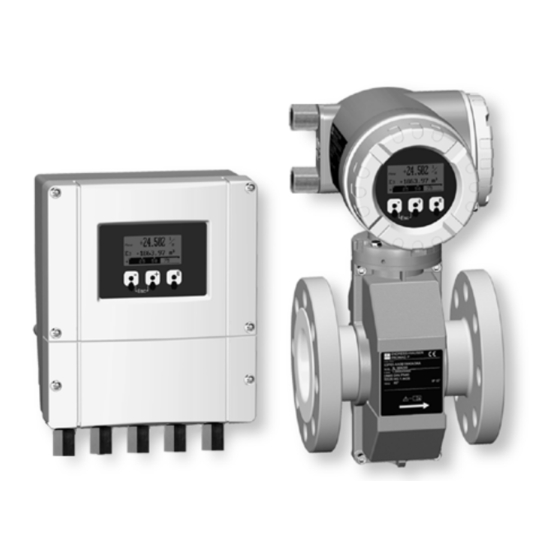
Proline Promag 50P, 53P
Electromagnetic Flow Measuring System
Flow rate measurement in chemical or process applications
Application
Electromagnetic flowmeter for bidirectional
measurement of liquids with a minimum conductivity
of ≥ 5 µS/cm:
• Acids and caustic solutions
• Paints
• Pastes, mashes
• Water, wastewater etc.
• Flow measurement up to 44,000 GPM
3
(9600 m
/h)
• Fluid temperature up to 356°F (180°C)
• Process pressures up to 580 psi (40 bar)
• Fitting lengths to DVGW/ISO
Application-specific lining materials:
• PTFE und PFA
Approvals for hazardous area:
• ATEX, FM, CSA, TIIS
Connection to process control system:
®
®
• HART
, Profibus
DP/PA, FOUNDATION™
®
Fieldbus, MODBUS
RS485
TI047D/24/ae/07.06
Your benefits
Promag measuring devices offer you cost-effective flow
measurement with a high degree of accuracy for a wide
range of process conditions.
The Proline transmitter concept comprises:
• Modular device and operating concept resulting in a
higher degree of efficiency
• Software options for batching, electrode cleaning and
for measuring pulsating flow.
• Uniform operating concept
The tried-and-tested Promag sensors offer:
• No pressure loss
• Not sensitive to vibrations
• Simple installation and commissioning
Advertisement

Related Manuals for Endress+Hauser Proline Promag 50P


Summary of Contents for Endress+Hauser Proline Promag 50P
- Page 1 Technical Information Proline Promag 50P, 53P Electromagnetic Flow Measuring System Flow rate measurement in chemical or process applications Application Your benefits Electromagnetic flowmeter for bidirectional Promag measuring devices offer you cost-effective flow measurement of liquids with a minimum conductivity measurement with a high degree of accuracy for a wide of ≥...
- Page 2 Proline Promag 50P, 53P Function and system design Measuring principle Faraday’s law of induction states that a voltage is induced in a conductor moving in a magnetic field. In electromagnetic measuring, the flowing medium corresponds to the moving conductor. The induced voltage is proportional to the flow velocity and is detected by two measuring electrodes and transmitted to the ampli- fier.
- Page 3 Proline Promag 50P, 53P Switching level: 3 to 30 V DC, independent of polarity Configurable for: totalizer(s) reset, measured value suppression, error-message reset, batching start/stop (optional), batch totalizer reset (optional) Current input (for Promag 53 only): Active/passive selectable, galvanically isolated, full scale value selectable, resolution: 3 µA, temperature coefficient: typ.
- Page 4 Proline Promag 50P, 53P PROFIBUS PA interface: • Transmission technology (Physical Layer): IEC 61158-2 (MBP), galvanically isolated • Profile version 3.0 • Current consumption: 11 mA • Permissible supply voltage: 9 to 32 V • Bus connection with integrated reverse polarity protection •...
- Page 5 Proline Promag 50P, 53P MODBUS interface: • Transmission technology (Physical Layer): RS485 in accordance with ANSI/TIA/EIA-485-A: 1998, galvanically isolated • MODBUS device type: Slave • Address range: 1 to 247 • Bus address adjustable via miniature switches or local display (optional) at the measuring device •...
-
Page 6: Table Of Contents
Proline Promag 50P, 53P Power supply Electrical connection Measuring unit b d/(g) PROFIBUS PA* HART* FOUNDATION Fieldbus* – 27 PA(–)/FF(–) + 26 PA(+)/FF(+) – 25 – + 24 – 23 – + 22 – – 21 + 20 N (L-) -
Page 7: N (L-)
Proline Promag 50P, 53P Terminal assignment, Promag 50 Terminal No. (inputs / outputs) Order variant 20 (+) / 21 (–) 22 (+) / 23 (–) 24 (+) / 25 (–) 26 (+) / 27 (–) Current output − − −... - Page 8 Proline Promag 50P, 53P Terminal No. (inputs / outputs) Order variant 20 (+) / 21 (–) 22 (+) / 23 (–) 24 (+) / 25 (–) 26 (+) / 27 (–) Current output 53***-***********M Status input Frequency output Frequency output...
- Page 9 1 = core, 2 = core insulation, 3 = core shield, 4 = core jacket, 5 = core strengthening, 6 = cable shield, 7 = outer jacket Optionally, Endress+Hauser also supplies reinforced connecting cables with an additional, metal strenghtening braid. We recommend such cables for the following cases: •...
- Page 10 Proline Promag 50P, 53P Supply voltage 85 to 260 V AC, 45 to 65 Hz 20 to 55 V AC, 45 to 65 Hz 16 to 62 V DC PROFIBUS PA and FOUNDATION Fieldbus Non-hazardous: 9 to 32 V DC...
- Page 11 Proline Promag 50P, 53P Metal, ungrounded piping In order to prevent outside influences on measurement, it is advisable to use ground cables to connect each sensor flange to its corresponding pipe flange and ground the flanges. Connect the transmitter or sensor con- nection housing, as applicable, to ground potential by means of the ground terminal provided for the purpose.
- Page 12 When using ground disks, note the following points: • Ground disks (1/2" to 12" / DN 15 to 300) can be ordered separately from Endress+Hauser as an accessory. • Ground disks (incl. seals) increase the installation length. You can find the dimensions of ground disks on Page 31.
- Page 13 Proline Promag 50P, 53P Performance characteristics Reference operating To DIN EN 29104 and VDI/VDE 2641: • Medium temperature: +28°C ± 2 K conditions • Ambient temperature: +22°C ± 2 K • Warm-up period: 30 minutes Installation: • Inlet run >10 x Dia. (DN) •...
- Page 14 Proline Promag 50P, 53P ³ 2 x Dia F06-5xxxxxxx-11-00-00-xx-000 Installation of pumps Do not install the sensor on the intake side of a pump. This precaution is to avoid low pressure and the conse- quent risk of damage to the lining of the measuring tube. Information on the lining's resistance to partial vac- uum can be found on Page 21.
-
Page 15: B (Rxd/Txd-P)
Proline Promag 50P, 53P Partially filled pipes Partially filled pipes with gradients necessitate a drain-type configuration. The Empty Pipe Detection (EPD) function offers additional protection by detecting empty or partially filled pipes. Caution! Risk of solids accumulating. Do not install the sensor at the lowest point in the drain. It is advisable to install a cleaning valve. - Page 16 Proline Promag 50P, 53P Orientation An optimum orientation helps avoid gas and air accumulations and deposits in the measuring tube. Promag, nevertheless, supplies a range of options and accessories for correct measuring of problematic mediums: • Electrode Cleaning Circuitry (ECC) to remove electrically conductive deposits in the measuring tube, e.g. in accretive mediums.
- Page 17 Proline Promag 50P, 53P Vibrations Secure the piping and the sensor if vibration is severe. Caution! It is advisable to install sensor and transmitter separately if vibration is excessively severe. Information on resistance to vibration and shock can be found on Page 20.
- Page 18 Proline Promag 50P, 53P Inlet and outlet runs If possible, install the sensor well clear of fittings such as valves, T-pieces, elbows, etc. Compliance with the following requirements for the inlet and outlet runs is necessary in order to ensure measuring accuracy: •...
- Page 19 Proline Promag 50P, 53P Length of connecting cable Permissible cable length Lmax depends on the conductivity of the medium. A minimum conductivity of 20 µS/cm is required for measuring demineralized water. ( S/cm] (10) (100) (200) F06-5xxxxxxx-05-xx-xx-xx-006 Gray shaded area = permissible range for medium conductivity Lmax = length of connecting cable in [m] µ...
- Page 20 Proline Promag 50P, 53P Degree of protection • Standard: NEMA 4X (IP 67) for transmitter and sensor • Optional: NEMA 6P (IP 68) for sensor in remote version Shock and vibration resistance Acceleration up to 2 g by analogy with IEC 60068-2-6...
- Page 21 Proline Promag 50P, 53P Conductivity Minimum conductivity: ≥ 5 µS/cm for fluids generally ≥ 20 µS/cm for demineralised water Note that in the case of the remote version, the minimum conductivity is also influenced by the length of the connecting cable → see “Length of connecting cable”...
- Page 22 Proline Promag 50P, 53P Limiting flow The diameter of the pipe and the flow rate determine the nominal diameter of the sensor. The optimum velocity of flow is 6 to 10 ft/s (2 to 3 m/s). The velocity of flow (v), moreover, has to be matched to the physical prop- erties of the medium: •...
- Page 23 Proline Promag 50P, 53P Flow characteristics (US units) Nominal Recommended Factory settings diameter flow rate Min./max. full scale value Full scale value Pulse weighting Creepage [inch] [mm] (v ~ 1 or ~ 33 ft/s) (v ~ 8 ft/s) (~ 2 pulse/s) (v ~ 0.1 ft/s)
- Page 24 Proline Promag 50P, 53P Measuring tube specifications Nominal diameter Pressure rating Inside diameter of measuring tube EN (DIN) AS 2129 AS 4087 ANSI with PFA with PTFE [mm] [inch] [bar] [lbs] inches (mm) inches (mm) − − − 1/2" PN 40 Cl 150 0.59 (15)
- Page 25 Proline Promag 50P, 53P 6.27" (159.5) 9.84" (250) 3.56" (90.5) 3.54" 1.77" 8.46" (90) (45) (215) 5.31" (135) 2.08" 3.18" 3.18" > 1.97" (53) (81) (81) (50) 4.01" (102) 2.08" (53) 3.74" 3.20" (95) (81.5) 0.45" 7.55" 0.45" (11.5) (192) (11.5)
- Page 26 Proline Promag 50P, 53P There is a separate mounting kit for the wall-mounted housing. It can be ordered from Endress+Hauser as an accessory. The following installation variants are possible: • Panel-mounted installation • Pipe mounting Panel-mounted installation +0.02 -0.02 8.27”...
- Page 27 Proline Promag 50P, 53P Compact version ≤ 12" (DN ≤ 300) 7.68" 8.94" (195) (227) 6.61" 8.15" * (168) (207) 6.30" (160) L (DVGW) F06-53Fxxxxx-06-00-xx-xx-000 EN (DIN) / JIS / ANSI inches inches inches inches inches inches [inch] (mm) (mm)
- Page 28 Proline Promag 50P, 53P Remote version ≤ 12" (DN ≤ 300) 6.73" 5.08" (171) (129) 5.63" (143) 4.01" (102) A0003219 EN (DIN) / JIS / ANSI inches inches inches inches inches inches [inch] (mm) (mm) (mm) (mm) (mm) (mm) [mm] 1/2"...
- Page 29 Proline Promag 50P, 53P Compact version ≥ 14" (DN ≥ 350) 8.94" 7.68" (227) (195) 6.61" 8.15" * (207) (168) 6.30" (160) * Blind version F06-53Fxxxxx-06-00-xx-xx-001 EN (DIN) ANSI inches inches inches inches inches inches [mm] [inch] (mm) (mm) (mm)
- Page 30 Proline Promag 50P, 53P Remote version ≥ 14" (DN ≥ 350) 6.73" (171) 5.63" 5.08" (143) (129) A0003220 EN (DIN) ANSI inches inches inches inches inches inches [mm] [inch] (mm) (mm) (mm) (mm) (mm) (mm) 14" 21.6 (550) 26.9 (683.5) 15.8 (401.5)
- Page 31 Proline Promag 50P, 53P Ground disk 1/2" to 12" (DN 15 to 300) Ø B Ø 0.26” (6.5) Ø di 0.39” (10) Ø D A0003221 EN (DIN) / JIS / ANSI inches inches inches inches [inch] (mm) (mm) (mm)] (mm) [mm] 1/2"...
- Page 32 Proline Promag 50P, 53P Weight Weight data in kg Nominal Compact version Remote version (without cable) diameter Sensor Wall housing [mm] [inch] EN (DIN) / ANSI EN (DIN) / ANSI 1/2" 14 lbs 10 lbs 13 lbs 1" 16 lbs...
- Page 33 Proline Promag 50P, 53P • AS 2129: (DN 25) A105 or RSt37-2 (S235JRG2) (DN 50) A105 oder St44-2 (S275JR) (with Al/Zn protective coating) • AS 4087: A105 or St44-2 (S275JR) (with Al/Zn protective coating) Ground disks: 1.4435/316L SSor Alloy C-22 Electrodes: 1.4435/316L SS, platinum/rhodium 80/20 or Alloy C-22, tantalum...
- Page 34 Proline Promag 50P, 53P Flange connection to ANSI B16.5 Flange material: A105 [p si] [bar] Class 300 Class 150 [°F] [°C] A0003226 Flange connection to ANSI B16.5 Flange material: F316L SS [bar] [psi] Class 300 Class 150 [°F] [°C] F06-xxFxxxxx-05-xx-xx-xx-002 Flange connection to JIS B2238 Flange material: RSt37-2 (S235JRG2) / H II / 1.0425...
- Page 35 Proline Promag 50P, 53P Fitted electrodes Measuring, reference and EPD electrodes • Standard available with 1.4435/316L SS, Alloy C-22, tantalum, platinum/rhodium 80/20 • Optional: measuring electrodes made of platinum/rhodium 80/20 Process connection Flange connection: • EN 1092-1 (DIN 2501), < DN 350 From A, > DN 300 From B (dimensions acc.
- Page 36 Proline Promag 50P, 53P Certificates and approvals Ex approvals Information about currently available Ex versions (ATEX, FM, CSA) can be supplied by your Endress+Hauser Sales Centre on request. All explosion protection data are given in a separate documentation which is available upon request.
- Page 37 Proline Promag 50P, 53P Accessories Various accessories, which can be ordered separately from Endress+Hauser, are available for the transmitter and the sensor. The Endress+Hauser service organisation can provide detailed information on request. Supplementary documentation • Flow Measurement (FA005D/06/en) • Operating Instructions Promag 50 (BA046D/06/en, BA049D/06/en) •...
- Page 38 Proline Promag 50P, 53P Ordering Information NOTE: Endress+Hauser reserves the right to change or modify product, specifications, and ordering information at any time without notice. Please consult Endress+Hauser or your local representative for the most recent information. Promag 50P Electromagnetic flowmeter...
- Page 39 Proline Promag 50P, 53P Promag 53P Electromagnetic flowmeter 10 11 12 Promag 53 P Nominal Diameter Housing NEMA 4X (IP 67) compact aluminum housing 1/2” 10” NEMA 4X (IP 67) remote wall-mounted (only for approvals A or R) 1” 3H 12”...
- Page 40 Canada Mexico Tel. +49 76 21 9 75 02 Fax +49 76 21 9 75 34 5 Endress+Hauser, Inc. Endress+Hauser Canada Endress+Hauser, México, S.A. de C.V. www.endress.com 2350 Endress Place 1075 Sutton Drive Av. Gustavo Baz No. 43 info@ii.endress.com Greenwood, IN 46143 Burlington, ON L7L 5Z8 Fracc.