Table of Contents
Advertisement
Owner's Manual
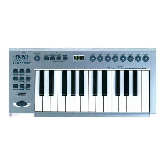
Thank you for purchasing the MIDI keyboard controller PCR-1.
Before using this unit, carefully read the sections entitled: "USING
THE UNIT SAFELY" and "IMPORTANT NOTES" (OWNER'S
MANUAL p. 2–4). These sections provide important information
concerning the proper operation of the unit. Additionally, in order
to feel assured that you have gained a good grasp of every feature
provided by your new unit, Owner's manual should be read in its
entirety. The manual should be saved and kept on hand as a
convenient reference.
Copyright © 2004 ROLAND CORPORATION
All rights reserved. No part of this publication may be reproduced in any
form without the written permission of ROLAND CORPORATION.
Advertisement
Table of Contents

Related Manuals for Roland Edirol PCR-1


Summary of Contents for Roland Edirol PCR-1
- Page 1 Owner’s Manual Thank you for purchasing the MIDI keyboard controller PCR-1. Before using this unit, carefully read the sections entitled: “USING THE UNIT SAFELY” and “IMPORTANT NOTES” (OWNER’S MANUAL p. 2–4). These sections provide important information concerning the proper operation of the unit. Additionally, in order to feel assured that you have gained a good grasp of every feature provided by your new unit, Owner’s manual should be read in its...
- Page 2 (except when this manual provides specific instructions directing you to do so). Refer all servicing to your retailer, the nearest Roland Service Center, or an authorized Roland distributor, as listed on the “Information” page. • Never use or store the unit in places that are: •...
-
Page 3: Using The Unit Safely
USING THE UNIT SAFELY • In households with small children, an adult should provide supervision until the child is capable of following all the rules essential for the safe operation of the unit. • Protect the unit from strong impact. (Do not drop it!) •... -
Page 4: Important Notes
However, in certain cases (such as when circuitry related to memory itself is out of order), we regret that it may not be possible to restore the data, and Roland assumes no liability concerning such loss of data. Additional Precautions •... - Page 5 • Use a cable from Roland to make the connection. If using some other make of connection cable, please note the following precautions. • Some connection cables contain resistors. Do not use cables that incorporate resistors for connecting to this unit. The use of such cables can cause the sound level to be extremely low, or impossible to hear.
-
Page 6: Contents Of The Package
Contents of the package The PCR-1 includes the following items. When you open the package, first make sure that all items are included. If any are missing, contact the dealer where you purchased the PCR-1. ● USB Audio Interface / MIDI Keyboard Controller PCR-1 fig.pcr-1... -
Page 7: Table Of Contents
Table of operating modes System settings Audio and MIDI flow Playing sounds on your computer Recording sound on your computer Digital recording the output of the PCR-1 on a CD/MD/DAT Startup mode Features Useful When Playing Pitch Bend Modulation Octave Shift... - Page 8 Protecting a memory set (PROTECT) ... 92 System settings ... 93 Appendices ... 99 Memory sets... 100 Troubleshooting ... 106 Problems related to the USB driver... 106 Problems when using the PCR-1 ... 111 MIDI implementation... 117 Main specifications... 122 index ... 123...
-
Page 9: Names Of Things And What They Do
Used to assign MIDI messages to the controllers. 6 Display Indicates the current status and various other information. Lights if the PCR-1 is connected to your computer via USB. DATA OUT This will blink when MIDI messages are transmitted via USB or MIDI OUT. - Page 10 Names of things and what they do fig.panel-2 7 Controllers [R1] – [R8] , [S1] ( [SHIFT] + [R1] ) – [S8] ( [SHIFT] + [R8] ) You can assign MIDI messages to these controllers. (➝Assign MIDI messages (EDIT) (p. 61)) When the [SHIFT] button is unlit (SHIFT OFF), these controllers correspond to [R1]--[R8].
- Page 11 13 TRANSPOSE / ENTER Button Use [TRANSPOSE] + [OCTAVE -/+] to transpose the pitch of the keyboard in semitone steps. Also, in any mode except PLAY mode, it functions as the [ENTER] button, which you need to press to confirm the settings you’ve made. 14 OCTAVE - / + Press [OCTAVE - / +] to shift the pitch of the keyboard up or down in steps of an octave.
-
Page 12: Rear Panel
Coaxial. • Use these jacks to output digital audio to a digital audio device such as a MD/DAT. On the PCR-1, the input from the input jacks cannot be output directly to the Digital output connector. • You can connect a set of headphones to this jack. The headphone jack will output the same signal as the master output jacks and digital output jacks. -
Page 13: Setup
This section explains how to install the drivers needed for connecting the PCR-1 to a computer, and make the necessary settings. Getting Connected and Installing Drivers (Windows) ... (p. 14) Getting Connected and Installing Drivers (Macintosh)... (p. 31) What is a driver? A “driver”... -
Page 14: Getting Connected And Installing Drivers (Windows)
Getting Connected and Installing Drivers (Windows) Installing the driver The installation procedure will differ depending on your system. Please proceed to one of the following sections, depending on the system you use. • Windows XP users ... (p. 14) • Windows 2000 users... (p. 20) •... - Page 15 “D:” may be different for your system. Specify the drive name of your CD- ROM drive. Use the USB cable to connect the PCR-1 to your computer. Near the task bar, your computer will indicate “Found New Hardware”. Please wait.
- Page 16 [Next]. Make sure that the “Model” field indicates “EDIROL PCR-1 WAVE” or “EDIROL PCR-1 MIDI”, and click [Next]. Driver installation will begin. If the “What action do you want Windows to take?” (Step 4) setting was not set to “Ignore”, a “Hardware Installation”...
- Page 17 [Next]. Make sure that the “Model” field indicates “EDIROL PCR-1 WAVE” or “EDIROL PCR-1 MIDI”, and click [Next]. Driver installation will begin. If the “What action do you want Windows to take?” (Step 4) setting was not set to “Ignore”, a “Hardware Installation”...
- Page 18 Getting Connected and Installing Drivers (Windows) If the “What action do you want Windows to take?” (Step 4) setting was not set to “Ignore”, a “Hardware Installation” dialog box will appear. If “What action do you want Windows to take?” is set to “Warn” A dialog box with a “!”...
- Page 19 ■ Enabling background processing In Windows XP, make settings to enable background processing. If you fail to make this setting, you may experience interruptions in the sound. To ensure that MIDI and audio processing occurs smoothly, use the following procedure to make settings. Open the System Properties dialog box.
-
Page 20: Windows 2000 Users
Getting Connected and Installing Drivers (Windows) Windows 2000 users Disconnect all USB cables except for a USB keyboard and USB mouse (if used). Open the System Properties dialog box. Click the Windows Start button, and from the menu that appears, select Settings | Control Panel. - Page 21 “D:” may be different for your system. Specify the drive name of your CD- ROM drive. Use the USB cable to connect the PCR-1 to your computer. If the “File signature verification” (Step 4) setting was not set to “Ignore”, a “Digital Signature Not Found”...
- Page 22 Getting Connected and Installing Drivers (Windows) If the “File signature verification” (Step 4) setting was not set to “Ignore,” a “Digital Signature Not Found” dialog box will appear. If “File signature verification” is set to “Warn” 1. Click [Yes]. 2. Continue the installation. The screen will indicate “Completing the Found New Hardware Wizard”.
- Page 23 The System Settings Change dialog box may appear. Click [Yes]. Windows will restart automatically. If the System Settings Change dialog box does not appear, restart Windows from the Start menu. If you changed “File signature verification” If you changed the “File signature verification” (p. 20) setting, restore the original setting after Windows restarts.
- Page 24 Getting Connected and Installing Drivers (Windows) ■ Enabling background processing In Windows 2000, make settings to enable background processing. If you fail to make this setting, you may experience interruptions in the sound. To ensure that MIDI and audio processing occurs smoothly, use the following procedure to make settings.
- Page 25 “D:” may be different for your system. Specify the drive name of your CD- ROM drive. Use the USB cable to connect the PCR-1 to your computer. The driver will be installed automatically. In the SetupInf dialog box, click [OK].
-
Page 26: Settings And Checking
Windows device settings, such as Media Player. For details on how to make these settings, refer to the owner’s manual for your software. For details on the PCR-1’s input/output devices, refer to Input / output devices (p. 44). Depending on how your... - Page 27 Windows device settings, such as Media Player. For details on how to make these settings, refer to the owner’s manual for your software. For details on the PCR-1’s input/output devices, refer to Input / output devices (p. 44). Getting Connected and Installing Drivers (Windows)
- Page 28 Windows device settings, such as Media Player. For details on how to make these settings, refer to the owner’s manual for your software. For details on the PCR-1’s input/output devices, refer to Input / output devices (p. 44). For details on the PCR-1’s...
-
Page 29: Adjusting The Audio Latency
Set “Audio Buffer Size” to the far left (Min). Click [OK] to close the driver settings dialog box. Restart the application that is using the PCR-1. Play back audio data on your application. If interruptions occur in the sound, repeat step 1 to step 5, and gradually increase the buffer size specified in step 2 until interruptions no longer occur. -
Page 30: Using Asio Direct Monitor
Getting Connected and Installing Drivers (Windows) Using ASIO Direct Monitor If the PCR-1's DIRECT MONITOR ON / OFF setting (p. 97) is AUTO, you can control the PCR-1's Direct Monitor settings from your ASIO 2.0 compatible software. Open the “Driver Settings” dialog box. -
Page 31: Getting Connected And Installing Drivers (Macintosh)
Insert the CD-ROM into the CD-ROM drive of your computer. In the Driver (Mac OS X) folder of the CD-ROM, double-click PCR1USBDriver.pkg. The display will indicate “Welcome to the EDIROL PCR-1 USB Driver Installer”. Click [Continue]. The display will indicate “Select a Destination”. -
Page 32: Setting The Audio Device
Before using the PCR-1 with your software, please note the following points. • Use the USB cable to connect the PCR-1 to your computer before you start up your software. • Do not disconnect the USB cable from the PCR-1 while your software is running. -
Page 33: Mac Os 9 Users
* Either OMS or FreeMIDI must be installed in your Macintosh, as appropriate for the sequencer software you are using. If a PCR-1 is already connected to your Macintosh when you install the driver, a message like the following will appear when the Macintosh is started up. -
Page 34: Setting The Driver
■ Setting the driver If you are using FreeMIDI, proceed to FreeMIDI settings (p. 36). OMS settings Use the USB cable to connect the PCR-1 to your computer. fig.3-3 From the CD-ROM, drag the Driver E (Mac OS 9) - OMS Setting folder into the Opcode - OMS Applications folder on the hard disk of your Macintosh to copy it there. - Page 35 From the Studio menu, choose Test Studio. fig.OMS3 Try moving the fader of the PCR-1. If the arrow beside number 1 or 2 in the diagram at right blinks, the settings have been made correctly.
-
Page 36: Freemidi Settings
Next, make MIDI device settings in your sequencer or other software. For details on how to make these settings, refer to the owner’s manual for your software. For details on the PCR-1’s input / output devices, refer to Input / output devices (p. 44). FreeMIDI settings Use the USB cable to connect the PCR-1 to your computer. - Page 37 Next, make MIDI device settings in your sequencer or other software. For details on how to make these settings, refer to the owner’s manual for your software. For details on the PCR-1’s input/output devices, refer to Input / output devices (p. 44). Getting Connected and Installing Drivers (Macintosh)
-
Page 38: Installing The Asio Driver
Getting Connected and Installing Drivers (Macintosh) ■ Installing the ASIO driver You must install the PCR-1 driver even if you will be using only audio on the PCR-1. Be sure to install the PCR-1 driver before you install the ASIO driver. - Page 39 Set “Buffer Size” to the far left (Min). Click [OK] to close the driver settings dialog box. Restart the application that is using the PCR-1. Play back audio data on your application. If interruptions occur in the sound, repeat step 1 to step 5, and gradually increase the buffer size specified in step 2 until interruptions no longer occur.
- Page 40 Getting Connected and Installing Drivers (Macintosh) Using ASIO Direct Monitor If the PCR-1's DIRECT MONITOR ON / OFF setting (p. 97) is AUTO, you can control the PCR-1's Direct Monitor settings from your ASIO 2.0 compatible software. Open the “Driver Settings” dialog box.
-
Page 41: Operation
Operation The PCR-1 is a controller that transmits MIDI messages. You cannot perform using only the PCR-1 by itself. You will need to connect it to a sound module or computer. The various controllers ( [R1–R8] , [S1–S8] , [B1–B6] , [L1–L3] ) can be assigned almost any message you want to get the control you need for your particular setup. -
Page 42: Basic Use
If you connect as shown in the diagram, you will be able to monitor the playback from your software or the sound from instruments or audio devices connected to the PCR-1. Audio cable... -
Page 43: Audio And Midi Flow
MIDI OUT DEVICE EDIROL PCR-1 MIDI IN DEVICE EDIROL PCR-1 1 EDIROL PCR 1 2 * For an explanation of the items in the diagram, refer to Input / output devices (p. 44). * For details on the actual operation, refer to Use MIDI functionality (p. 50). -
Page 44: Input / Output Devices
For details on these settings, refer to the owner’s manual for your software. * If you are unable to select the PCR-1 in the device settings for your software, it is possible that the PCR- 1 driver was not installed correctly. Please reinstall the driver. -
Page 45: Two Midi Ports
MIDI sound module PCR-1 1 PCR-1 2 The output destination of the MIDI messages transmitted when you operate the PCR-1’s knobs, and buttons can be specified separately for each controller. (Assign MIDI messages (EDIT) (p. 61)) fig.midi-port.e Normally, you will connect your MIDI keyboard to the... -
Page 46: Use Audio Functionality
* You will no longer hear sound from the internal speaker of your computer. * The PCR-1 is not equipped with its own MIDI sound generator. This means that MIDI data from your computer cannot be played by the PCR-1. -
Page 47: Recording Sound On Your Computer
• Use the Input volume (p. 12) to adjust the input level.Check the input level on the application that you using. • You must set the PCR-1’s sample rate to match the sampling frequency used by your application.(➝ USB AUDIO MODE SETTING (p. 96)) In order for the sampling frequency setting to take effect, you exit applications and disconnect the USB cable from the PCR-1, then connect it again. - Page 48 Be careful of looped connections fig.loop If the PCR-1 is connected as shown above to a device that outputs (“thru-s”) the input audio (such as a cassette player that is in recording mode), turning on the Input monitor switch will cause the sound to loop between the PCR-1 and the other device, causing oscillation and producing an unexpectedly high volume.
-
Page 49: Digitally Recording Sound From Your Computer
Use an optical digital cable to connect your recording device to the Digital output jack. * Signals input through the PCR-1's input jacks cannot be directly output from the digital output jack. The digital output jack always outputs only the audio signal that is being sent from the computer. -
Page 50: Use Midi Functionality
(i.e., the button that is lit). Alternatively, press the [CANCEL] button. The setting you were in the process of making will be discarded. Switching modes When you turn on the power, the PCR-1 will start up in PLAY mode. Press the [MIDI CH] . -
Page 51: Startup Mode
Once you have finished making settings, try playing the keyboard. When you play the keyboard in PLAY mode, MIDI messages are sent to the application. * Since the PCR-1 does not contain a sound generator, you cannot play MIDI data using the PCR-1 alone. Use MIDI functionality... -
Page 52: Features Useful When Playing
Octave Shift and Transpose can be set independently. To switch the PCR-1 to PLAY mode... The PCR-1 will automatically start up in PLAY mode when you connect the PCR-1 to your computer by USB cable. To return to PLAY mode from another mode (➝Setting the MIDI Transmit Channel (p. 53)), press the button of the current mode (i.e., the button that is lit). -
Page 53: Setting The Midi Transmit Channel
Setting the MIDI Transmit Channel To control your sound module, set the PCR-1's current channel to the MIDI receive channel that's selected on your sound module. Use MIDI Channel mode to set the current channel. Current channel The "current channel" is the transmit channel for the keyboard, bender switch, and modulation button. -
Page 54: Setting The Input Mode
If you want to input decimal numbers, press the [DECIMAL] button. If you want to input hexadecimal numbers, press the [HEX] button. When you connect the PCR-1 to your computer by USB cable, the PCR-1 will start up in Decimal mode. -
Page 55: Selecting Sounds On A Sound Module (Sending Program Change / Bank Select Massages)
Selecting Sounds on a Sound Module (Sending Program Change / Bank Select Massages) To select a sound on your MIDI sound module, transmit a Program Change in Program Change mode. To select a sound from a different bank, first use Bank mode to transmit a Bank Select message that switches the bank. - Page 56 Use MIDI functionality Program Change Mode (PROGRAM CHANGE) This mode lets you transmit a program change message on the current channel (p. 53). fig.PC-1_90 fig.program Press the [SHIFT] button so it is lit. Press the [PGM CHANGE] button. The [PGM CHANGE] button will light. The display will indicate the program change that was transmitted most recently.
- Page 57 Bank mode (BANK) This mode lets you transmit a bank select (MSB, LSB) message on the current channel. The program change message you most recently transmitted (specified) in Program Change mode (p. 56) will also be transmitted following the bank select message. fig.BANK2_90 fig.bank Press the [SHIFT] button so it is lit.
-
Page 58: Transmitting A Reset Message
Use MIDI functionality Transmitting a Reset message (What to do if there are “stuck” MIDI notes) If notes on a connected MIDI sound module become “stuck”, or if there is something wrong with the sound, you can execute the Panic function to solve the problem. When you execute the Panic function, All sound off, All notes off, and Reset all controllers messages will be transmitted on all channels. -
Page 59: Changing The Memory Sets
(EDIT) (p. 61). If you edit the controller settings of a memory you recall, and want to keep your changes, you must save the memory before powering down the PCR-1. For the procedure, refer to Saving a memory set (SAVE) (p. 88). -
Page 60: Transmitting The Current Controller Values All At Once (Snapshot)
Use MIDI functionality Transmitting the current controller values all at once (SNAPSHOT) Once you have set the various controllers to the desired settings, you can transmit a detailed description of this state in the form of a “snapshot”. When you execute this function, the current values of the controllers [R1–R8] or [S1–S8] will be transmitted. -
Page 61: Assign Midi Messages (Edit)
Assign MIDI messages (EDIT) You can assign the following functions to a controller. You will use Edit mode to assign MIDI messages. NOTE AFTERTOUCH CONTROL CHANGE PROGRAM CHANGE NRPN Sys Ex TEMPO (20-250) * If you want to assign a single-byte system message (system realtime message, tune request) or a freely specified message of up to 24 bytes, refer to Sys Ex. -
Page 62: Specifying The Button Mode
Off message is transmitted. Messages will be sent to “PCR-1 1” PORT 1 PORT 2 Messages will be sent to “PCR-1 2” PORT 1, 2 Messages will be sent to both “PCR-1 1” and “PCR-1 2”... -
Page 63: Note Assign
■ NOTE ASSIGN Here’s how to assign a Note message to a controller. In addition to being used to play sounds, note messages can also be used to control a sequencer. Mode Keyboard Basic mode Advanced mode Basic mode fig.edt2 Press the [EDIT] button. -
Page 64: Advanced Mode
Use MIDI functionality Advanced mode 1 Advanced mode 1 of NOTE ASSIGN lets you specify the velocity value in addition to the items of Basic mode. 1. Press the [EDIT] button. 2. Slightly move the controller to which you want to assign a Note message. In the case of a button, press that button. -
Page 65: Aftertouch Assign
■ AFTERTOUCH ASSIGN Here’s how to assign an Aftertouch message to a controller. Mode Basic mode Advanced mode 1 Advanced mode 2 Advanced mode 3 Basic mode fig.edt2 Press the [EDIT] button. The display will indicate “EDT.” fig.r-1 Slightly move the controller to which you want to assign an Aftertouch message. - Page 66 Use MIDI functionality Advanced mode 1–3 Advanced mode 1 of AFTERTOUCH ASSIGN lets you specify the upper and lower limits of the aftertouch value in addition to the items of Basic mode. Advanced modes 2 and 3 let you specify an aftertouch message for an individual note (Polyphonic Key Pressure) instead of specifying the channel.
- Page 67 Specifying the range of values (upper and lower limits) If in Edit mode you selected an Assign type (p. 61) that lets you specify the range of values, you will need to specify the upper limit and lower limit of the value. * Normally, when using Decimal input mode, the value you are specifying appears in the display as a three digit number.
-
Page 68: Control Change Assign
Use MIDI functionality ■ CONTROL CHANGE ASSIGN Here’s how to assign a control change message to a controller. Mode keyboard Basic mode Advanced mode 1 Advanced mode 2 Basic mode fig.edt2 Press the [EDIT] button. The display will indicate “EDT”. fig.r-1 Slightly move the controller to which you want to assign a Control Change message. - Page 69 Advanced mode 1 Advanced mode 1 of CONTROL CHANGE ASSIGN lets you specify the upper and lower limits of the control change value in addition to the items of Basic mode. 1. Press the [EDIT] button. 2. Slightly move the controller to which you want to assign a Control Change message. In the case of a button, press that button.
- Page 70 Use MIDI functionality Advanced mode 2 Advanced mode 2 simulates the operation of a conventional rotary encoder. If this is assigned to a controller, moving that controller toward the right (upward) of center will have the same effect as turning the encoder clockwise, and moving the controller toward the left (downward) of center will have the same effect as turning the encoder counterclockwise.
-
Page 71: Program Change Assign
■ PROGRAM CHANGE ASSIGN Here’s how to assign a program change message to a controller. Mode Number Basic mode Advanced mode 1 Advanced mode 2 Advanced mode 3 Advanced mode 4 Basic mode fig.edt2 Press the [EDIT] button. The display will indicate “EDT.” fig.r-1 Slightly move the controller to which you want to assign a Program Change message. - Page 72 Use MIDI functionality Advance mode 1, 2 Advanced mode 1 of PROGRAM CHANGE ASSIGN lets you specify the upper and lower limits of the program change value. Advanced mode 2 lets you transmit BANK LSB/MSB settings in addition to the program change. 1.
- Page 73 Advanced modes 3 and 4 Advanced mode 3 lets you assign the Program Change Decrement function (PC DEC) to a controller. Advanced mode 4 lets you assign the Program Change Increment function (PC INC) to a controller. 1. Press the [EDIT] button. 2.
-
Page 74: Rpn / Nrpn Assign
Use MIDI functionality ■ RPN / NRPN ASSIGN Here’s how you can assign an RPN or NRPN message to a controller. Mode Keyboard Basic mode Advanced mode 1 fig.edt2 Press the [EDIT] button. The display will indicate “EDT”. fig.r-1 Slightly move the controller to which you want to assign an RPN or NRPN message. - Page 75 Press the [ENTER] button. fig.BANK-3 Use the [DEC] [INC] buttons or the [0] – [F] keys to specify the RPN LSB (CC#100) or NRPN LSB (CC#98). Press the [ENTER] button. If you are making an assignment for a button, specify the button mode. (➝Specifying the button mode (p.
- Page 76 Use MIDI functionality Advanced mode In Advanced mode for RPN/NRPN, you can specify the upper and lower limit of the data entry MSB (CC#06) value when the RPN/NRPN message is transmitted, as well as the various settings available in Basic mode. 1.
-
Page 77: Sys Ex. Assign
■ Sys Ex. ASSIGN Here’s how you can assign a system exclusive message to a controller. Advanced mode 2 lets you assign a single-byte system message (System realtime message, tune request). Advanced modes 3 and 4 let you assign any desired message. (Input up to 24 bytes) Key- Mode board... - Page 78 11. Input the second and subsequent bytes in the same way. 12. After you have input the number of bytes you specified in step 7, the PCR-1 will check whether the messages you’ve input are indeed valid MIDI messages. If there is a problem, the display will indicate “ERR”.
-
Page 79: Specifying The Checksum
• Inputting channel/block data (p. 81) Specifying the checksum The PCR-1 can automatically calculate the checksum of a system exclusive message and embed it in the message. In order to use this function, you must use the following procedure to specify the starting location from which the checksum is calculated, and the location at which the checksum is inserted. -
Page 80: Specifying The Location Of The Data
Use MIDI functionality Specifying the location of the data Here’s how to specify the location and data type of the variable portion (data) within a system exclusive message. The range of data values will be the default range in the case of Basic mode or Advanced mode 3. - Page 81 (The block number is not actually a channel, but corresponds to the “part” within a GS sound module. On the PCR-1, this corresponds to the channel for the sake of convenience.) Current channel For an actual example, refer to Bend Pitch Control (p.
- Page 82 Use MIDI functionality ■ Examples of assigning system exclusive messages • GM2 System On (p. 82) • Master Volume (p. 83) • Bend Pitch Control (p. 84) GM2 System On F0 7E 7F 09 03 F7 Here’s how to assign a GM2 System On system exclusive message in Basic mode. 1.
-
Page 83: Master Volume
Master Volume F0 7F 7F 04 01 vL vM F7 Since a Master Volume message has a data range of 00 00–7F 7F and we do not need to specify the range, we will use Basic mode. Since the two bytes of data are in the order of LSB and then MSB, we will select “DT3”... - Page 84 Use MIDI functionality Bend Pitch Control Since the GS Bend Pitch Control message has a data range of 40H–58H (0–24 semitones), we will select Advanced mode 1, which lets us specify the range. Since the data format is one byte, we will select “DT0”...
-
Page 85: Tempo Assign
■ TEMPO ASSIGN You can assign a controller to adjust the speed (20–250) of the F8 Clock message. * In order to transmit F8 Clock messages, the F8 CLOCK setting must be “ON”. (➝“F8 CLOCK ON/OFF” (p. 94)) fig.edt2 Press the [EDIT] button. The display will indicate “EDT.”... -
Page 86: Copying A Midi Message Assignment (Assign Copy)
Use MIDI functionality Copying a MIDI message assignment (ASSIGN COPY) Here’s how a message assigned to a controller can be copied to another controller. fig.edt2 Press the [EDIT] button. The display will indicate “EDT”. fig.r-1 Slightly move the controller to which you want to copy the assignment (the “copy destination”). -
Page 87: Canceling A Midi Message Assignment (No Assign)
Canceling a MIDI message assignment (NO ASSIGN) Here’s how you can cancel the message assigned to a controller. Once its assignment is cancelled, no message will be transmitted when you operate that particular controller. fig.edt2 Press the [EDIT] button. The display will indicate “EDT”. fig.r-1 Slightly move the controller whose assignment you want to cancel. -
Page 88: Saving A Memory Set (Save)
Use MIDI functionality Saving a memory set (SAVE) Here’s how to save the settings of the current memory into internal memory. You can save settings into internal memory numbers 1–F. You cannot save to memory number 0 (GM2). * After you edit the settings, perform the “SAVE” operation as needed. If you turn off the power without performing “SAVE”, your changes will be lost. -
Page 89: Transmitting/Receiving Bulk Data (Bulk)
Use the [DEC] [INC] buttons or the [0] [1] keys to select the mode. fig.rs1 Confirm what’s indicated and press the [ENTER] button. The third digit of the display will blink, and the PCR-1 will wait to receive bulk data. The received data will overwrite the current memory. Memo- SINGLE BULK ries 1–F will not be affected. - Page 90 Single Bulk or All Bulk Transmit bulk data from your sequencer or other device. Specify “PCR” (Mac OS 9: PCR-1 1) as the MIDI output device for your sequencer software. For details on this setting, refer to the manual of your sequencer software.
-
Page 91: Transmit Mode
Use the [DEC] [INC] buttons or the [0] [1] keys to select the mode. Confirm what’s indicated and press the [ENTER] button. fig.ts-1 The third digit of the display will blink, and the PCR-1 will wait to transmit bulk data. Press the [ENTER] button. -
Page 92: Protecting A Memory Set (Protect)
Use MIDI functionality Protecting a memory set (PROTECT) If you turn the Protect setting ON, ALL BULK (p. 89) reception and SAVE (p. 88) operations will be disabled. fig.edt2 Press the [EDIT] button. The display will indicate “EDT”. fig.ptc Press the [PROTECT] key. The display will blink “PTC”. -
Page 93: System Settings
System settings Here’s how you can make various system settings for the PCR-1. fig.edt2 Press the [EDIT] button. The display will indicate “EDT”. fig.sy0 Press the [SYSTEM] key. The display will indicate “SY0”. Use the [0] - [8] , [A] - [E] keys to specify the System setting that you want to set, and then press the [ENTER] button. -
Page 94: Velocity Offset
System settings F8 CLOCK ON / OFF (Keyboard : 0) Perform steps 1-3. fig.hyo 4. Use the [DEC] [INC] buttons or the [0] or [1] keys to switch F8 CLOCK ON / OFF. The display will indicate either “ON” or “OFF”. 5. -
Page 95: H-Activity On / Off
(p. 88) regardless of the state in which the power was turned off. LAST ACCESS Upon power-up, the PCR-1 will recall the memory that MEMORY was last recalled or saved into current memory (p. 88). -
Page 96: Usb Audio Sampling Frequency
In Advanced mode, audio signals can be transferred be- 48kHz tween the PCR-1 and the computer at a resolution of 24 (ADVANCE) bits and sampling frequencies of 44.1 / 48 / 96 kHz. Se-... -
Page 97: Pitch Bend Time
Settings or operations in your ASIO 2.0 application (e.g., Cubase) AUTO will switch Direct Monitor ON / OFF. The input signal from the audio input jacks will be output to the PCR-1’s speakers, headphone jack, and master output jacks. System settings... - Page 98 MEMO...
-
Page 99: Appendices
Appendices This section contains troubleshoooting information and explanations of convenient functions.You may read this material as necessary. Memory sets ...p. 100 Troubleshooting...p. 106 MIDI implementation ...p. 117 Main specifications...p. 122... -
Page 100: Memory Sets
For details on settings for actually using each memory set with your application, refer to the Read Me file for each memory set, located in the Memory Files folder of the CD-ROM. Since the PCR-1 does not have controllers [P1] and [P2], the PCR-1 itself is unable to transmit or edit the messages assigned to these controllers. - Page 101 ■ MCR-8 MODE 3 (SONAR 2) SET When using this memory set, turn the PCR-1’s OMNI (p. 54) setting OFF. MCR-8 MODE 3 (SONAR 2) - A (MEMORY: 1) Message Parameter Range (Hex.) (Hex.) TRACK 1 CC 16(10) TRACK 2...
-
Page 102: Memory Sets
Memory sets ■ MCR-8 MODE 4 (Cubase 5/SX) SET When using this memory set, turn the PCR-1’s OMNI (p. 54) setting OFF. MCR-8 MODE 4 (Cubase 5/SX) - A (MEMORY: 5) Message Parameter Range (Hex.) (Hex.) TRACK 1 PAN CC 72(48) - Page 103 B0 0F 0E B0 2F dd HOLD CC 64(40) EXPRESSION CC 11(0B) ■ GS SET When using this memory set, you will find it convenient to turn the PCR-1’s OMNI (p. 54) setting ON. GS-A (MEMORY: A) Parameter REVERB MACRO REVERB CHARACTER REVERB PRE-LPF...
- Page 104 Memory sets GS-B (MEMORY: B) Parameter CHORUS MACRO CHORUS PRE-LPF CHORUS DELAY CHORUS RATE CHORUS DEPTH CHORUS FEEDBACK CHORUS LEVEL PART PANPOT CHORUS SEND LEVEL TO REVERB CHORUS SEND LEVEL TO DELAY TVF CUTOFF FREQ TVF RESONANCE MODULATION DEPTH BEND RANGE CHORUS SEND LEVEL PART LEVEL PROGRAM CHANGE DEC...
- Page 105 ■ XG SET When using this memory set, you will find it convenient to turn the PCR-1’s OMNI (p. 54) setting ON. XG-A (MEMORY: D) Parameter BEND PITCH CONTROL BEND FILTER CONTROL BEND AMPLITUDE CONTROL PITCH EG INITIAL LEVEL PITCH EG ATTACK TIME...
-
Page 106: Troubleshooting
• Is the PCR-1 connected correctly? Make sure that the USB connector of your computer is connected to the PCR-1 by a USB cable. • Is the CD-ROM correctly inserted into your CD-ROM drive? Installation is not possible unless the CD-ROM included with the PCR-1 is inserted in your CD- ROM drive. - Page 107 Macintosh, and then restart it. In some cases, the PCR-1 will not be detected if you have connected it to the USB connector located on the keyboard of the Macintosh. Please connect it to a USB connector on the Macintosh itself.
- Page 108 In this case, you may be able to solve the problem by connecting a USB hub. If the above actions do not solve the problem, it is possible that the PCR-1 has been incorrectly detected by the computer. Please reinstall the driver from the beginning of the procedure. (Getting...
- Page 109 “Found unknown device” appears even though you installed the driver If your computer or USB hub has two or more USB connectors, and you connect the PCR-1 to a USB connector to which the PCR-1 has never been connected before, the “Unknown device” dialog box may appear even on a computer onto which you have already installed the driver.
-
Page 110: Deleting The Driver
Troubleshooting ■ Deleting the driver If you were unable to install the driver according to the procedure given, the PCR-1 may not be recognized correctly by the computer. In this case, use the following procedure to delete the driver, and then follow the procedure to install the driver once again. -
Page 111: Problems When Using The Pcr-1
In your playback software, have you specified the audio data output destination? For some software, such as Cool Edit Pro LE, you will need to specify the PCR-1 as the output destination for audio data. For details on the procedure for making settings, refer to the owner’s manual for your software. - Page 112 If your ASIO-compatible software does not support 24-bit audio input/output, it will not operate correctly if you select [PCR-1 ASIO1.0 24bit] or [PCR-1 ASIO2.0 24bit] as the ASIO driver. In this case, select either [PCR-1 ASIO1.0 16bit] or [PCR-1 ASIO2.0 16bit] as the ASIO driver.
- Page 113 If this occurs, you may be able to solve the problem by connecting a USB hub that contains its own power supply. In some cases you may be able to solve this problem in the “EDIROL PCR-1 Driver settings” dialog box.
- Page 114 • In the “Memory” Control Panel, set Virtual Memory to “Off.” • Depending on the way in which you connect to the Internet, use the PCR-1 with the following settings. If you connect to the Internet via a LAN cable Use while the LAN cable is connected.
- Page 115 Was a heavy processing load experienced while using the PCR-1, such as accessing the CD-ROM drive or a network? If an operation involving a heavy processing load is performed while the PCR-1 is in use, it may not operate correctly. If this occurs, stop playback/recording, and then try resuming playback/ recording.
- Page 116 Make sure that the PCR-1 is selected as the MIDI input/output device (port) in the software that you want to control. If the PCR-1 is connected via USB, you can use two ports for controlling your software. Make sure that the desired port is correctly selected. (➝Audio and MIDI flow (p. 43)) •...
-
Page 117: Midi Implementation
EOX (End of Exclusive) ●Data transmission The PCR-1 can use Bulk Dump (p. 119) to transfer its internal Memory sets (p. 100). ❍Data Set 1 DT1 (12H) These messages transmit the actual data, and are used to transfer data settings to a device. -
Page 118: Program Change
* Transmitted by rightward/leftward operation of the BENDER lever in Play mode. ■Channel mode messages In addition to the channel mode messages that can be transmitted in Panic mode, the PCR-1 lets you assign any channel voice message to any controller and transmit ●Channel mode messages Status 2nd byte... -
Page 119: System Exclusive Message
For example, this can be used to store all settings of a device into a computer or sequencer. On the PCR-1, a bulk dump will be transmitted when you execute the Bulk mode operation BULK TX. The bulk dump is transmitted as several exclusive messages. - Page 120 05. ●Checksum calculation In order to verify that the message was received correctly, Roland exclusive messages (RQ1, DT1) add a checksum following the end of the data (before the F7). The checksum value is determined by the address and data (or size) of the exclusive message that is transmitted.
- Page 121 USB AUDIO INTERFACE / MIDI KEYBOARD CONTROLLER Model PCR-1 Function... Basic Default Channel Changed Default Mode Messages Altered Note Number : True Voice Note On Velocity Note Off After Key’s Touch Channel’s Pitch Bend 0-119 Control Change Program : True Number...
-
Page 122: Main Specifications
Main specifications ■ PCR-1: USB Audio Interface / MIDI Keyboard Controller ● Number of Audio Record/Playback Channels Record: 1 pair of stereo Playback: 1 pair of stereo Full duplex (except for 96 kHz setting) ● Signal Processing AD/DA Conversion: 24 bits... -
Page 123: Index
index Active sensing ... 118 Advanced mode ... 61, 96 AFTERTOUCH ... 61, 65–66 AFTERTOUCH ASSIGN ... 61, 65–66 Aftertouch message ... 65 ALL BULK ... 89, 91–92 All notes off ... 58, 118 All sounds off ... 58, 118 AppleTalk ... - Page 124 MIDI CH / BANK SEL Button ... 9 MIDI Channel mode ... 50, 53 MIDI Devices ... 44 MIDI flow ... 43 MME EDIROL PCR-1 In ... 44 MME EDIROL PCR-1 Out ... 44 Modulation ... 52, 117 MODULATION Button ... 11 MODULATION SETTING ...
- Page 125 PANIC ... 50, 58 Panic mode ... 50, 58 PC DEC ... 71, 73 PC INC ... 71, 73 PCR-1 ... 44 PCR-1 1 ... 44 PCR-1 2 ... 44 pitch ... 11, 52 Pitch Bend ... 52 Pitch bend change ... 118 PITCH BEND TIME ...
- Page 126 index Template sheets ... 6 TEMPO ... 61, 85 TEMPO ASSIGN ... 61 Timing Clock ... 118 Toggle mode ... 62 Transmit data ... 117 TRANSPOSE ... 52 TRANSPOSE / ENTER Button ... 11 Tune request ... 118 Universal non-realtime system exclusive ... 119 Universal non-realtime system exclusive message ...
-
Page 127: Declaration Of Conformity
DECLARATION OF CONFORMITY Compliance Information Statement Type of Equipment : Responsible Party : NOTICE AVIS Model Name : PCR-1 USB AUDIO INTERFACE/MIDI KEYBOARD CONTROLLER Edirol Corporation North America Address : 425 Sequoia Drive, Suite 114, Bellingham, WA 98226 Telephone : (360) 594-4276... - Page 128 Information When you need repair service, call your nearest EDIROL/Roland Service Center or authorized EDIROL/Roland distributor in your country as shown below. HONG KONG Parsons Music Ltd. 8th Floor, Railway Plaza, 39 EUROPE Chatham Road South, T.S.T, EDIROL (Europe) Ltd.