Table of Contents
Advertisement
Quick Links
This .pdf document is bookmarked
Operating Instructions and Parts Manual
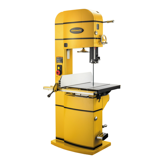
18-, 20-, 24-inch Band Saws
Models PM1800B, PM2013B, PM2415B
PM2013B shown
Powermatic
427 New Sanford Road
LaVergne, Tennessee 37086
Part No. M-1791800B
Ph.: 800-274-6848
Revision B 02/2018
www.powermatic.com
Copyright © 2018 Powermatic
Advertisement
Table of Contents

Related Manuals for Powermatic PM1800B


Summary of Contents for Powermatic PM1800B
- Page 1 This .pdf document is bookmarked Operating Instructions and Parts Manual 18-, 20-, 24-inch Band Saws Models PM1800B, PM2013B, PM2415B PM2013B shown Powermatic 427 New Sanford Road LaVergne, Tennessee 37086 Part No. M-1791800B Ph.: 800-274-6848 Revision B 02/2018 www.powermatic.com Copyright © 2018 Powermatic...
-
Page 2: Warranty And Service
1.0 Warranty and service Powermatic warrants every product it sells against manufacturers’ defects. If one of our tools needs service or repair, please contact Technical Service by calling 1-800-274-6846, 8AM to 5PM CST, Monday through Friday. Warranty Period The general warranty lasts for the time period specified in the literature included with your product or on the official Powermatic branded website. -
Page 3: Table Of Contents
2.0 Table of contents Section Page 1.0 Warranty and service ............................. 2 2.0 Table of contents ............................3 3.0 IMPORTANT SAFETY INSTRUCTIONS ....................... 5 4.0 About this manual ............................7 5.0 Features and Terminology ..........................7 6.0 Specifications ..............................8 7.0 Base hole centers ............................ - Page 4 17.1.3 Complete Machine with Accessories – PM2415B Exploded View I ............ 37 17.1.4 Complete Machine with Accessories – PM2415B Exploded View II ........... 38 17.1.5 Complete Machine with Accessories – PM1800B, PM2013B and PM2415B – Parts List ....39 17.2.1 Upper Wheel Assembly – Exploded View ................... 43 17.2.2 Upper Wheel Assembly –...
-
Page 5: Important Safety Instructions
Do not use this band saw for other than its generated from wood products. intended use. If used for other purposes, Powermatic disclaims any real or implied 20. Wood products emit chemicals known to the warranty and holds itself harmless from any State of California to cause birth defects or injury that may result from that use. - Page 6 26. Keep safety guards in place at all times when 33. Use the right tool at the correct speed and feed machine is in use. If removed for maintenance rate. Do not force a tool or attachment to do a purposes, use extreme caution and replace the job for which it was not designed.
-
Page 7: About This Manual
Additional knowledge can be obtained from experienced users or trade articles. Whatever accepted methods are used, always make personal safety a priority. If there are questions or comments, please contact your local supplier or Powermatic. Powermatic can also be reached at our web site: www.powermatic.com. -
Page 8: Specifications
..............72 dB at 39” (1000mm) from blade, without load subject to local/national electrical codes. for 460V, magnetic switch (part no. PM1800B-043C) must be purchased separately and installed. A qualified electrician is recommended. the specified values are emission levels and are not necessarily to be seen as safe operating levels. As workplace conditions vary, this information is only intended to allow the user to make a better estimation of the hazards and risks involved. - Page 9 Stand footprint (PM2415B) ............. 37-1/2"L x 20-3/8"W x 2"H (956 x 518 x 51 mm) Overall dimensions, assembled (PM1800B) ......... 38" x 42" x 81-1/2" (965 x 1067 x 2070mm) Overall dimensions, assembled (PM2013B) ....... 40" x 42" x 81-1/2" (1016 x 1067 x 2070mm) Overall dimensions, assembled (PM2415B) .......
- Page 10 PM2415B-3 ................ 968 lb (439 kg) ........1067 lb (484 kg) The specifications in this manual were current at time of publication, but because of our policy of continuous improvement, Powermatic reserves the right to change specifications at any time and without prior notice, without incurring obligations.
-
Page 11: Base Hole Centers
7.0 Base hole centers PM1800B PM2013B PM2415B Figure 2... -
Page 12: Setup And Assembly
Hoist or forklift, with straps/hooks Figure 3: contents (items not to scale) 8mm hex wrench (provided) Square Hardware for PM1800B/2013B (Figure 3a): Socket head button screws, M8x20 – HP-1 Remove all crating and plastic from around Socket head button screws, M8x16 – HP-2 machine. -
Page 13: Rear Rail
Exposed metal surfaces, such as table surface and Install guide rail to bottom holes in front rail, blade guides, have been given a protective coating using five M8x16 button screws (HP-2), with at the factory. This coating should be removed with lock washers and flat washers (HP-5/4). -
Page 14: Resaw Fence
8.7 Resaw fence Refer to Figures 8 and 9. Loosen lock bar using the knobs, until lock bar protrudes enough to slide aluminum resaw fence on from either end, as shown in Figure 8. Re-tighten knobs. NOTE: The aluminum resaw fence can be installed in one of two positions;... -
Page 15: Setting Fence Parallel To Blade
Use a gauge to carefully measure distance from miter slot to straight edge. Take measurements at both front and back of table – these should be the same. If miter slot is not parallel to blade, loosen the four hex cap screws (17mm wrench) that secure the table to the trunnion (Figure 14 shows three of them), and shift table as needed until miter slot is parallel to blade. -
Page 16: Fence Locking Tightness
The three phase Band Saw may be converted to size machine – 600 CFM is recommended. 460V operation: Replace 230V contactor with 460V magnetic contactor (part no. PM1800B-043C, purchased separately). Re-connect motor leads according to diagram inside motor junction box. (Similar diagrams are found in sect. -
Page 17: Extension Cords
9.4 Extension cords Use of extension cords is discouraged; try to position machines within reach of the power source. If an extension cord becomes necessary, be sure to use one heavy enough to carry the current your product will draw. An undersized cord will cause a drop in line voltage resulting in loss of power and overheating. -
Page 18: Installing/Changing Blades
Figure 22: blade removal Figure 21: setting table stop 10.3 Installing/changing blades Always wear gloves when handling blades. New blades are usually packaged in a coiled position; to prevent injury uncoil them slowly and carefully, while wearing work gloves and safety glasses. Refer to sect. -
Page 19: Blade Tracking
Rotate tension handwheel (C, Figure 24) until scale pointer (Figure 25) reaches appropriate measurement for blade width. Figure 26: blade track IMPORTANT: Make tracking adjustments with knob (F, Figure 24) while blade is at full tension. DO NOT use screws (G, Figure 24); these were used by the Figure 25: blade tension scale manufacturer for wheel alignment and should NOT TIP: Use the band saw’s gauge setting initially. -
Page 20: Upper Thrust Bearing
Loosen locking screw (A, Figure 27). Make sure NOTE: Do not force guide bearing against side knob (C, Figure 28) is tightened. of blade. It should only make contact with blade when there is pressure from cutting operation. Tighten locking screw (D ) and remove dollar bill. -
Page 21: Guide Post
10.10 Guide post parallelism Adjust lower guide and thrust bearings below table, using similar procedure as for upper The guide post should be parallel to blade guides. throughout the vertical travel of the guide post; thus Movement summary: Loosen locking lever (G) the guide bearings will maintain their relationship to to move guide bracket using dial (H)(Knob J the blade at any height from the table and won’t... -
Page 22: Miter Gauge
Remove fence plate and mount resaw pin to the slot needed. Retighten hex nut (D) when adjustment in the fence body, securing it with the knob, as is finished. shown. The resaw pin is usually positioned so that its center is approximately even with front edge of blade. -
Page 23: Drive Belt Tension And Replacement
Disconnect machine from power source. Open upper and lower doors and remove blade. Remove screw from lower wheel shaft and remove lower wheel. Loosen motor lock handle. Raise motor lift handle and retighten motor lock handle to hold motor in raised position. Remove old belt and install new one, making sure it seats properly in the pulley grooves. -
Page 24: Wheel Brush
10.15 Wheel brush IMPORTANT: An interlock switch prevents the band saw from starting if the blade is de-tensioned. Blade Refer to Figure 39. must be tensioned for start switch to activate. Likewise, if the blade breaks during operation, the The brush (A) must contact tire to clear it of dust and band saw motor will shut off. -
Page 25: Operation
12.2 Ripping 12.0 Operation Ripping is cutting lengthwise down the workpiece, The following section contains basic information, and with the grain (of wood stock). See Figure 41. and is not intended to cover all possible applications Always use a push stick or similar device when or techniques using the Band Saw. -
Page 26: Resawing
12.4 Resawing • Fence is not parallel to miter slot and blade. Resawing is the process of slicing stock to reduce • Blade is not tensioned correctly. its thickness, or to produce boards that are thinner • Blade is dull. than the original workpiece, such as veneers. -
Page 27: Maintenance
13.0 Maintenance Before doing maintenance on the machine, disconnect it from the electrical supply by pulling out the plug or switching off the main switch! Failure to comply may cause serious injury. Clean the band saw regularly to remove any resinous deposits and sawdust. -
Page 28: Blade Selection
14.0 Blade Selection Using the proper blade for the job will increase the operating efficiency of your band saw, help reduce necessary saw maintenance, and improve your productivity. Thus, it is important to follow certain guidelines when selecting a saw blade. Here are factors to consider when selecting a blade: •... -
Page 29: Set
high speed cobalt steel edge welded to it), or carbide tips. Because of the importance of blade selection, it is recommended that you use the blade selection guide, sect. 14.0. Also, listening to experienced band saw users will produce valuable information as to the types of blades currently on the market along with their pros and cons. -
Page 30: Blade Selection Guide
15.0 Blade Selection Guide Identify the material and thickness of your workpiece. The chart will show the recommended PITCH, blade TYPE, and FEED RATE. Key: H – Hook L – Low S – Skip M – Medium R – Regular H –... -
Page 31: Troubleshooting Pm1800B/2013B/2415B Band Saws
16.0 Troubleshooting PM1800B/2013B/2415B Band Saws 16.1 Operational Problems Table 3 Symptom Possible Cause Correction Table tilt does not hold Locking lever is not tight. Tighten locking lever (A, Figure 19). position under load. Trunnion locking mechanism is broken Replace trunnion locking mechanism. - Page 32 Symptom Possible Cause Correction Blade forms cracks at Replace with proper blade for job. Teeth not suitable for particular job, or base of teeth. are incorrectly set. Blade thickness not suitable for band Replace with proper thickness blade. wheel diameter. Blade sharpened incorrectly, becomes Sharpen blade properly or replace.
-
Page 33: Mechanical And Electrical Problems
16.2 Mechanical and Electrical Problems Table 4 Trouble Probable Cause Remedy Machine will not Verify machine is connected to power start/restart or No incoming power. source, and that the safety key is repeatedly trips circuit installed on the switch. breaker or blows Cord damaged. -
Page 34: Replacement Parts
Non-proprietary parts, such as fasteners, can be found at local hardware stores, or may be ordered from Powermatic. Some parts are shown for reference only, and may not be available individually. -
Page 35: Complete Machine With Accessories - Pm 1800B & 2013B Exploded View I
17.1.1 Complete Machine with Accessories – PM 1800B & 2013B Exploded View I... -
Page 36: Complete Machine With Accessories - Pm 1800B & 2013B Exploded View Ii
17.1.2 Complete Machine with Accessories – PM 1800B & 2013B Exploded View II... -
Page 37: Complete Machine With Accessories - Pm2415B Exploded View I
17.1.3 Complete Machine with Accessories – PM2415B Exploded View I... -
Page 38: Complete Machine With Accessories - Pm2415B Exploded View Ii
17.1.4 Complete Machine with Accessories – PM2415B Exploded View II... -
Page 39: Complete Machine With Accessories - Pm1800B, Pm2013B And Pm2415B - Parts List
....PM2013B-013 ... Lower Cabinet Door ..................1 ....PM2415B-013 ... Lower Cabinet Door ..................1 14 ....PM1800B-014 ... Saw Blade, Hook type…………………………160”L / 3/4” / 0.65mm THK ..1 ....PM2013B-014 ... Saw Blade, Hook type …………………………170”L / 1” / 0.9mm THK ..1 .... - Page 40 (for 2415B) 62 ....PM1800B-062 ... Bracket......................1 63 ....PM1800B-063 ... Hex Socket Button Head Screw ......M5 x 35 ......1 65 ....PM1500-063 ....Pointer ......................1 66 ....TS-1503061 ....Hex Socket Hd Cap Screw ........M6 x 25 ......2 67 ....
- Page 41 ....PM1800B-120MF ..Motor Fan (not shown)................... 1 ....PM1800B-120MFC ... Motor Fan Cover (not shown) ................ 1 ....PM1800B-120SC ..Starting Capacitor (not shown) ........ 300MFD, 250VAC ..1 ....PM1800B-120RC ..Running Capacitor (not shown) ....... 45μf, 450VAC ....1 ....
- Page 42 153 .... JWS25X-405 ..... Star Washer ............. M5 ......... 2 154 .... PM1800B-154 ... Wire Cap ..............P4 ......... 3 155 .... PM1800B-155 ... Phillips Pan Head Machine Screw (Big) ....M5 x 10 ......4 156 .... PM1800B-156 ... Motor Protective Plate ................... 1 157 ....
-
Page 43: Upper Wheel Assembly - Exploded View
2 ....PM1800B-018-02 ..Spacer ......................1 3 ....BB-6306LLU ....Ball Bearing ............. 6306LLU ....... 2 4 ....PM1800B-018-04 ..Plate....................... 1 5 ....PM1800B-018-05 ..Phillips Pan Head Machine Screw ......M6 x 8 ......3 6 ....PM1800B-018-06 ..Tire......................... 1... -
Page 44: Lower Wheel Assembly - Exploded View
3 ....BB-6306LLU ....Ball Bearing ............. 6306LLU ....... 2 4 ....PM1800B-018-04 ..Plate....................... 1 5 ....PM1800B-018-05 ..Phillips Pan Head Machine Screw ......M6 x 8 ......3 6 ....PM1800B-022-06 ..Pulley ............... ø190mm/218mm ... 1 7 .... -
Page 45: Upper Wheel Sliding Bracket Assembly -Exploded View
17.4.1 Upper Wheel Sliding Bracket Assembly –Exploded View Part Assembly No.: PM1800B-027 (#1~26) / PM2013B-027 (#1~7-1, 8~26) / PM2415B-027 (#1~7-2, #8~26) 17.4.2 Upper Wheel Sliding Bracket Assembly –Part List 1 ....PM1800B-027-01 ..Spring ......................1 2 ....PM1800B-027-02 ..Flat Washer ....................1 3 .... -
Page 46: Brake Linkage Assembly - Exploded View
Index No. Part No. Description Size 1 ....PM1800B-122-01 ..Brake Arm ..............L:573mm ....... 1 ....PM2013B-122-01 ..Brake Arm ..............L:607mm ....... 1 ....PM2415B-122-01 ..Brake Arm ..............L:662mm ....... 1 2 ....TS-1550041 ....Flat Washer ............. M6 x ø13 ....... 4 3 .... -
Page 47: Lower Blade Guide Support Assembly - Exploded View
5 ....PM1800B-059-05 ..Retaining Ring ............S15 ....... 2 6 ....PM1800B-059-06 ..Lower Eccentric Shaft ..................2 7 ....PM1800B-059-07 ..Lower Blade Guide Support Bracket ............. 1 8 ....PM1800B-059-08 ..Knob ......................3 9 .... -
Page 48: Upper Blade Guide Support Assembly - Exploded View
5 ....PM1800B-059-05 ..Retaining Ring ............S15 ....... 2 6 ....PM1800B-143-06 ..Upper Eccentric Shaft ..................2 7 ....PM1800B-143-07 ..Upper Blade Guide Support Bracket ............. 1 8 ....PM1800B-059-08 ..Knob ......................4 9 .... -
Page 49: Trunnion Support Bracket Assembly - Exploded View
Size 1 ....PM1800B-124-01 ..Carriage Bolt ....................1 2 ....PM1800B-124-02 ..Trunnion Block (Front) ................... 1 3 ....PM1800B-124-03 ..Trunnion Support Bracket ................1 4 ....PM1800B-124-04 ..Trunnion Block (Back) ................... 1 5 .... -
Page 50: Guide Bar Bracket Assembly - Exploded View
Description Size 1 ....PM1800B-128-01 ..Socket Set Screw ............ M7 x 10 ......4 2 ....TS-1503021 ....Socket Head Cap Screw ......... M6 x 1 x 10 ....2 3 ....TS-1504031 ....Socket Head Cap Screw ......... M8 x 1.25 x 16 ....4 4 .... -
Page 51: Gear Bracket Assembly - Exploded View
2 ....PM1800B-131-02 ..Bearing Cover ....................1 3 ....BB-6002ZZ ....Ball Bearing ............. 6002ZZ ......1 4 ....PM1800B-131-04 ..Phillips Pan Head Machine Screw ......M8 x 1.25 x 16 ....1 5 ....PM1800B-131-05 ..Worm Shaft ....................1 6 .... -
Page 52: Miter Gauge Assembly - Exploded View
17.11.1 Miter Gauge Assembly – Exploded View Part Assembly No.: PM1800B-149 17.11.2 Miter Gauge Assembly – Parts List Index No. Part No. Description Size 1 ....6295167 ....Miter Gauge Body ..................1 2 ....TS-1533062 ....Pan Head Screw ............M5 x 0.8 x 20 ....3 3 .... -
Page 53: Fence Assembly - Exploded View
12 ....TS-1541021 ....Nylon Lock Hex Nut ..........M6 ......... 1 13 ....PM1800B-150-13 ..Nylon Set Screw ............M12 x 1.75 x 16 .... 3 14 ....TS-1525011 ....Socket Set Screw ............ M10 x 1.5 x 10 ....2 15 .... - Page 54 28 ....TS-2285121 ....Phillips Flat Head Machine Screw ......M5 x 0.8 x 12 ....2 29 ....PM1800B-150-29 ..Scale Label ....................1 30 ....PM1800B-150-30 ..Rear Rail (for 1800B & 2013B) ........ L:767mm ....... 1 ....PM2415B-150-30 ..Rear Rail (for 2415B) ..........L:927mm ....... 1 31 ....
-
Page 55: Electrical Connections
18.0 Electrical Connections 18.1 Electrical Connections – 5HP 1PH 230V BLACK POWER WHITE SUPPLY JUNCTION BLOCK BLACK 1~ 230V WHITE MAGNETIC SWITCH ASSEMBLY LIMIT CONTROL PANEL SWITCH WHITE BLACK BLACK BLACK BLACK WHITE YELLOW BLACK 230V BLACK BLACK BLACK WHITE BLUE GREEN START... -
Page 56: Electrical Connections - 5Hp 3Ph 230V
18.2 Electrical Connections – 5HP 3PH 230V BLACK POWER WHITE SUPPLY JUNCTION BLOCK BLACK 3~ 230V WHITE MAGNETIC SWITCH ASSEMBLY LIMIT CONTROL PANEL SWITCH WHITE BLACK BLACK BLACK BLACK WHITE 11 12 YELLOW BLACK 230V BLACK BLACK BLACK WHITE GREEN BLACK BLACK BLACK... -
Page 57: Electrical Connections - 5Hp 3Ph 460V
18.3 Electrical Connections – 5HP 3PH 460V BLACK POWER WHITE SUPPLY JUNCTION BLOCK BLACK 3~ 460V WHITE MAGNETIC SWITCH ASSEMBLY LIMIT CONTROL PANEL SWITCH WHITE BLACK BLACK BLACK BLACK WHITE 11 12 YELLOW BLACK 230V BLACK BLACK BLACK WHITE GREEN BLACK BLACK BLACK... - Page 58 This page intentionally left blank.
- Page 59 This page intentionally left blank.
- Page 60 427 New Sanford Road LaVergne, Tennessee 37086 Phone: 800-274-6848 www.powermatic.com...