Table of Contents
Advertisement
Quick Links
Advertisement
Table of Contents

Related Manuals for Powermatic PM253BT


Summary of Contents for Powermatic PM253BT
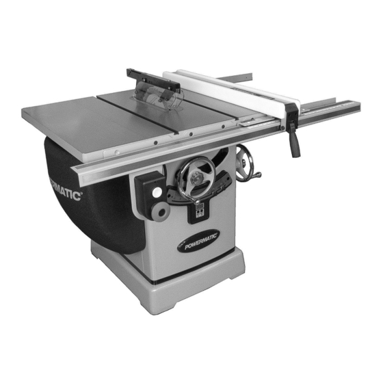
- Page 1 Operating Instructions and Parts Manual 10-inch Cabinet Saw Model PM2000B Shown with 30-inch rail set Powermatic 427 New Sanford Road LaVergne, Tennessee 37086 Part No. M-PM231BM / PM253BT Ph.: 800-274-6848 Edition 2 08/2018 www.powermatic.com Copyright © 2017 Powermatic...
-
Page 2: Important Safety Instructions
If used for other purposes, 18. Provide for adequate space surrounding work Powermatic disclaims any real or implied area and non-glare, overhead lighting. warranty and holds itself harmless from any injury that may result from that use. -
Page 3: Kickback
1.1 Kickback 27. Check the saw blade for cracks or missing teeth. Do not use a cracked or dull blade or one The most common accidents among table saw with missing teeth or improper set. Make sure users, according to statistics, can be linked to the blade is securely locked on the arbor. -
Page 4: About This Manual
Additional knowledge can be obtained from experienced users or trade articles. Whatever accepted methods are used, always make personal safety a priority. If there are questions or comments, please contact your local supplier or Powermatic. Powermatic can also be reached at our web site: www.powermatic.com. -
Page 5: Table Of Contents
3.0 Table of contents Section Page 1.0 IMPORTANT SAFETY INSTRUCTIONS ....................... 2 1.1 Kickback ..............................3 2.0 About this manual ............................4 3.0 Table of contents ............................5 4.0 Table Saw terminology ........................... 7 5.0 Specifications for PM2000B ........................... 8 6.0 Setup and assembly ............................. - Page 6 15.0 Electrical Connections ..........................43 15.1 PM2000B Wiring diagram – 3HP, 230V, 1PH ..................43 15.2 PM2000B Wiring diagram – 5HP, 400V, 3PH ..................44 16.0 Warranty and Service ..........................45...
- Page 7 (This is a dangerous, unacceptable kerf opening in the workpiece during a cutting procedure – always use appropriate devices to feed operation. (Powermatic table saws use the superior the workpiece through the saw blade during cutting riving knife system instead.) operations.)
-
Page 8: Specifications For Pm2000B
5.0 Specifications for PM2000B Table 1 Model number PM2000B Stock number – saw only PM231BM PM253BT (see Table 2 below for kit configurations) Motor and Electricals Motor type Totally enclosed, fan cooled, induction Horsepower 3 HP 5 HP Motor phase... - Page 9 Main materials Main table cast iron Table insert aluminum Extension wings cast iron Cabinet steel Base steel Center trunnion cast iron Bearing arm cast iron Pulleys steel General Dimensions Base footprint 23 x 28 in. (584 x 711 mm) Assembled, w/ extension wings only, L x W x H 42-5/8 x 32-3/4 x 40-3/8 in.
-
Page 10: Setup And Assembly
Read and understand the entire contents of this manual before attempting set- up or operation. Failure to comply may cause serious injury. 6.0 Setup and assembly 6.1 Shipping contents See Figure 6-1. Remove all accessory boxes from shipping pallet. Remove items from inside cabinet. Do not discard any packing material until saw is assembled and running satisfactorily. -
Page 11: Unpacking And Cleanup
The saw must be discon- nected from power source during assembly. Failure to comply may cause serious injury. 6.3 Unpacking and cleanup Use a hoist to lift saw off pallet; or remove nailed boards holding saw cabinet to pallet and slide saw off pallet onto floor. -
Page 12: Handwheel, Knobs, Levers
Tighten both clamps to align front and back edges of tables. Make sure front edge of wing remains flush with front edge of saw table. Tighten screws incrementally, and position straight edge at various places across seam, especially checking at the center. Make further adjustments as needed. -
Page 13: Installing And Removing Blade
To remove blade, engage arbor lock and remove nut with wrench. 6.10 Installing guard/knife assembly See Figure 6-10. 6.10.1 Riving knife Remove table insert. Raise blade arbor to highest position and set blade tilt to 0°. Pull clamp lever (S , Figure 6-9) upward. -
Page 14: Dust Port
Lower pawl assembly onto center notch of 7.0 Electrical connections riving knife, with pawls straddling knife. Push and hold button on pawl block (O , Figure 6-10), and push pawl block down until it securely Electrical connections must be engages in notch. made by a qualified electrician in compliance with all relevant codes. -
Page 15: Magnetic Switch And Safety Key
resulting in loss of power and overheating. Table 3 shows correct size to use depending on cord length and nameplate ampere rating. If in doubt, use the next heavier gauge. The smaller the gauge number, the heavier the cord. Amp Rating Volts Total length of cord (ft.) More... -
Page 16: Adjustments
8.5 Miter gauge 8.0 Adjustments Refer to Figures 8-2 and 8-3. 8.1 Tools required for adjustments 8.5.1 Setting miter angle Hex keys: 2.5mm, 3mm, 4mm The miter gauge has rack and pinion adjustment for Wrenches: 13mm, 19mm, 22mm (or adjustable) setting angle. -
Page 17: Blade Tilt Stop Adjustment
Set miter gauge at 90º to blade (0º setting on If adjustment is required, loosen nut on 90° stop scale) by loosening lock handle (H, Figure 8-2), screw (Figure 8-5) with 13mm wrench, and turn then pulling out spring-loaded knob (J) and screw to proper height. -
Page 18: Riving Knife Alignment
8.7 Riving knife alignment 8.7.1 Lateral alignment Saw blade and riving knife must be as closely aligned possible (lateral alignment) prevention of kickback. This should be checked upon initial blade guard and riving knife installation. Alignment should also be reaffirmed after each blade change. -
Page 19: Belt Adjustment
Raise miter gauge slightly out of its slot to serve Loosen screw (C, Figure 8-12) with 17mm as a shoulder. Using a sliding square (B) wrench. against the side of the bar, slide the scale over 1-1/4” (or Slightly loosen (D) with until it touches the tip of the blade, and lock adjustable) wrench. -
Page 20: Dro Calibration And Operation
Release buttons and display will show “45.0”. 8.10 DRO calibration and operation 10. Calibration at 45° is complete. (If “45.0” does When the 0° and 45° blade tilt stops have been not display, disconnect from power, reconnect verified to be correct, the DRO (digital readout) can and repeat above procedure.) be calibrated to match the settings. - Page 21 Wear a safety face shield, goggles, or safety Before starting a rip cut, verify glasses. that fence is clamped securely and aligned Do not use miter gauge and rip fence in the properly. same operation unless provision is made by use of a facing board on the fence, to allow ...
- Page 22 In ripping, use one hand to hold the board down If the table saw is used for against the fence or fixture, and the other to push it resawing, take precautions such as using an into the blade between blade and fence. If auxiliary fence, resaw barrier or similar devices workpiece is narrower than 6"...
- Page 23 Have the blade extend about 1/8" above the top of the workpiece. Exposing the blade above this point can be hazardous. 9.5 Bevel and miter operations Bevel cut – A bevel cut is a special type of operation where the saw blade is tilted at an angle less than 90-degrees to the table top (Figure 9-10).
-
Page 24: Safety Devices
Have the blade extend only 1/8" above the top of the 10.0 Safety devices workpiece. Exposing the blade above this point can be hazardous. 10.1 Feather board 9.6 Dado cutting Feather boards, or “combs,” can be purchased at Dadoing is cutting a wide groove into a workpiece or most tool stores, or made by the operator to suit cutting a rabbet along the edge of a workpiece. - Page 25 Figure 9-14: push block template Figure 9-15: push stick template...
-
Page 26: User-Maintenance
If the arbor needs to be removed for bearing replacement, it should be done by a Wipe down table surface and T-slots. qualified service technician. Contact Powermatic Clean pitch and resin from saw blade. customer service. WEEKLY: 11.5 Additional servicing... -
Page 27: Optional Accessories
12.0 Optional accessories These accessory items (purchased separately) can enhance the functionality of your PM2000B table saw. Contact your dealer to order, or call Powermatic at the phone number on the cover. Additional accessories may be available; see our website. -
Page 28: Troubleshooting Pm2000B Cabinet Saw
13.0 Troubleshooting PM2000B Cabinet Saw 13.1 Motor and electrical problems Symptom Probable Cause Remedy Saw will not start. No incoming power. Check plug connection. Safety key removed from switch. Install safety key. Low voltage. Check power line for proper voltage. Open circuit in motor or loose Inspect all connections on motor for loose or connection. -
Page 29: Replacement Parts
Replacement parts are listed on the following pages. To order parts or reach our service department, call 1-800- 274-6848 Monday through Friday (see our website for business hours, www.powermatic.com). Having the Model Number and Serial Number of your machine available when you call will allow us to serve you quickly and accurately. -
Page 30: Pm2000B Table And Cabinet Assembly I - Exploded View
14.1.1 PM2000B Table and Cabinet Assembly I – Exploded View... -
Page 31: Pm2000B Table And Cabinet Assembly Ii - Exploded View
14.1.2 PM2000B Table and Cabinet Assembly II – Exploded View... -
Page 32: Pm2000B Table And Cabinet Assembly - Parts List
28 ....TS-2311081 ....Hex Nut .............. M8-1.25 ......1 29 ....PM2000B-129 ....Cable Tie ....................2 30 ....PM2000B-130 ....Powermatic Logo ..................1 31 ....TS-1550041 ....Flat Washer ............6.7 x 16 x 2.0T mm ..2 32 .... - Page 33 Index No Part No Description Size 59 ....F009923 ......Socket Head Button Screw ........ M4-0.7 x 6L ....1 60 ....PM2000B-160 ....Oil Hose Fitting ........... PT1/4" x PH1/4" .... 1 61 ....TS-1503061 ....Socket Head Cap Screw ........M6-1.0 x 25L ....4 62 ....
- Page 34 Index No Part No Description Size 120 .... PM2000B-1120 ....O-Ring ..............P29 ....... 2 121 .... PM2000B-1121 ....Piston ....................... 1 122 .... PM2000B-1122 ....Drive End Bell ..................1 ....LM000304 ....... Warning Label (not shown) ..............1 ....
-
Page 35: Pm2000B Motor And Trunnion Assembly I - Exploded View
14.2.1 PM2000B Motor and Trunnion Assembly I – Exploded View... -
Page 36: Pm2000B Motor And Trunnion Assembly Ii - Exploded View
14.2.2 PM2000B Motor and Trunnion Assembly II – Exploded View... -
Page 37: Pm2000B Motor And Trunnion Assembly - Parts List
14.2.3 PM2000B Motor and Trunnion Assembly – Parts List Index No Part No Description Size 1 ....TS-1541031 ....Nylon Lock Hex Nut ........... M8-1.25 ......1 2 ....F006042 ......C-Retaining Ring, Ext ......... STW-14 ......1 3 ....PM2000B-203 ....Compression Spring ................. 1 4 .... - Page 38 Index No Part No Description Size 60 ....PM2000B-260E ....Motor..............3HP 230V 50Hz 1PH ... 1 ....PM2000B-260SC .... Starting Capacitor ..........400MFD 125VAC ..1 ....PM2000B-260RCE ..Running Capacitor ..........50µF 350VAC ....1 ....PM2000B-260FE ..... Fan (12 vanes) ..................1 ....
- Page 39 108 .... PM2000B-2108 ....Safety Key ....................1 109 .... PM2000B-2109 ....Switch Plate ..................... 1 110 .... PM2000B-2110 ....Strain Relief (3HP, 1PH) ........SR-7R3 ......2 ....PM2000B-2110A ..... Strain Relief (5HP, 3PH) ........SR-8R3 ......2 111 ....
-
Page 40: Pm2000B Blade Guard And Miter Gauge Assemblies - Exploded View
14.3.1 PM2000B Blade Guard and Miter Gauge Assemblies – Exploded View... -
Page 41: Pm2000B Blade Guard And Miter Gauge Assemblies - Parts List
14.3.2 PM2000B Blade Guard and Miter Gauge Assemblies – Parts List Index No Part No Description Size ....PM2000B-BGA ....Blade Guard Assembly (includes #1 thru 17) ........... 1 1 ....TS-1541021 ....Nylon Lock Hex Nut ........... M6-1.0 ......8 2 .... -
Page 42: Pm2000B Motor Cover Assembly - Exploded View
14.4.1 PM2000B Motor Cover Assembly – Exploded View 14.4.2 PM2000B Motor Cover Assembly – Parts List Index No Part No Description Size ....6827044B ......Motor Cover Assembly (includes #1 thru 10) ........... 1 1 ....PM2000B-401 ....Motor Cover ..................... 1 2 .... -
Page 43: Electrical Connections
15.0 Electrical Connections 15.1 PM2000B Wiring diagram – 3HP, 230V, 1PH BLACK WHITE GREEN GREEN OVERLOAD RELAY MAGNETIC CONTACTOR BLACK BLACK WHITE WHITE YELLOW WHITE BLACK WHITE BLACK GREEN... -
Page 44: Pm2000B Wiring Diagram - 5Hp, 400V, 3Ph
15.2 PM2000B Wiring diagram – 5HP, 400V, 3PH... -
Page 45: Warranty And Service
Powermatic sells through distributors only. The specifications listed in Powermatic printed materials and on the official Powermatic website are given as general information and are not binding. Powermatic reserves the right to effect at any time, without prior notice, those alterations to parts, fittings, and accessory equipment which they may deem necessary for any reason whatsoever. - Page 46 427 New Sanford Road LaVergne, Tennessee 37086 Phone: 800-274-6848 www.powermatic.com...