Table of Contents
Advertisement
This Manual is Bookmarked
Operating Instructions and Parts Manual
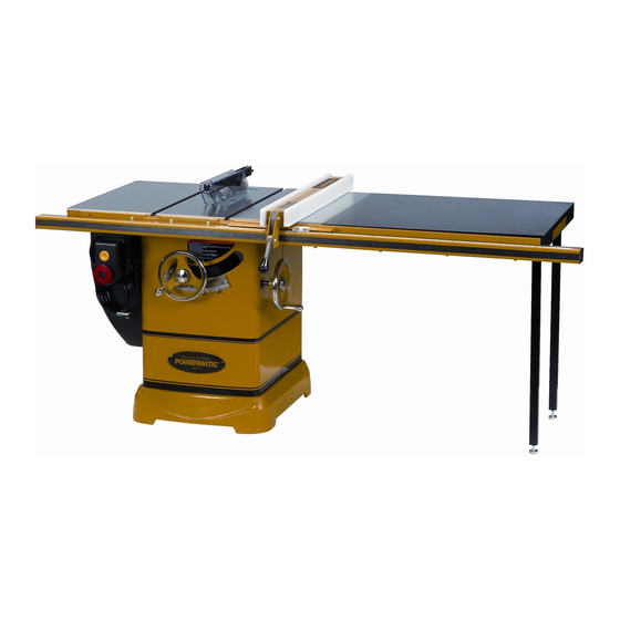
10-inch Cabinet Saw
Model: 2000
Model 2000 Table Saw shown with optional extension table and legs
WMH TOOL GROUP
2420 Vantage Drive
Elgin, Illinois 60123
Part No. M-1791997
Ph.: 800-274-6848
Revision B 04/06
www.wmhtoolgroup.com
Copyright © WMH Tool Group
Advertisement
Table of Contents

Related Manuals for Powermatic 2000


Summary of Contents for Powermatic 2000
- Page 1 This Manual is Bookmarked Operating Instructions and Parts Manual 10-inch Cabinet Saw Model: 2000 Model 2000 Table Saw shown with optional extension table and legs WMH TOOL GROUP 2420 Vantage Drive Elgin, Illinois 60123 Part No. M-1791997 Ph.: 800-274-6848 Revision B 04/06 www.wmhtoolgroup.com...
-
Page 2: Warranty And Service
This warranty covers only the initial purchaser of the product. WHAT IS THE PERIOD OF COVERAGE? The general POWERMATIC warranty lasts for the time period specified in the product literature of each product. WHAT IS NOT COVERED? The Five Year Warranty does not cover products used for commercial, industrial or educational purposes. Products with a Five Year Warranty that are used for commercial, industrial or education purposes revert to a One Year Warranty. -
Page 3: Table Of Contents
Troubleshooting ... 27 Optional Accessories ... 28 Ordering Replacement Parts... 28 Model 2000 Table Saw Parts List ... 29 Wiring Diagrams... 38 The specifications in this manual are given as general information and are not binding. WMH Tool Group reserves the right to effect, at any time and without prior notice, changes or alterations to parts, fittings, and accessory equipment deemed necessary for any reason whatsoever. -
Page 4: Warnings
5. Do not use this table saw for other than its intended use. If used for other purposes, WMH Tool Group disclaims any real or implied warranty and holds itself harmless from any injury that may result from that use. - Page 5 Make sure the blade is securely locked on the arbor. 27. Keep hands clear of the blade area. Do not reach past the blade to clear parts or scrap with the saw blade running. Never saw freehand. Avoid awkward operations and hand positions where a sudden slip could cause your hand to contact the blade.
-
Page 6: Introduction
This manual is provided by WMH Tool Group covering the safe operation and maintenance procedures for a Powermatic Model 2000 Table Saw. This manual contains instructions on installation, safety precautions, general operating procedures, maintenance instructions and parts breakdown. This machine has been designed and constructed to provide years of trouble free operation if used in accordance with instructions set forth in this manual. -
Page 7: Shipping Contents
Make sure that the castors do not get damaged when removing from the skid. The Table Saw should be placed in an area with a sturdy level floor, good ventilation and sufficient lighting. Leave enough space around the machine for mounting extension wings and rail assemblies, and loading and off-loading stock and general maintenance work. -
Page 8: Contents Of The Shipping Container
Contents of the Shipping Container Main Saw Container Table Saw (A) Table Insert (B) The following items are inside the saw: Miter Gauge Assembly (C) Blade Guard Assembly (D) Switch in box (E) Owner's Manual (F) Warranty Card (not shown) - Page 9 Extension Tables Two extension tables are packaged in individual boxes. Extension Tables Side Cover Box Hinge Pin (N) Side Cover (O) Contents of Side Cover Box Fence and Rail Carton contents and installation instructions for the fence, rail system, and optional wooden extension table are described in the Accu-Fence Owner's Manual (No.
-
Page 10: Assembly
3. Make sure that the front edge of the extension wings are flush with the front edge of saw table (Figure 2). 4. Level the extension wing with the saw table... -
Page 11: Lock Knobs And Swivel Handles
Dust Chute Referring to Figure 5: The Model 2000 comes equipped with a dust chute and hose assembly (Inset 2) for use with a dust collection system. If you do not intend to use a dust collection... -
Page 12: Blade Installation/Replacement
5. Install the blade, making sure the cutting teeth at the top of the blade point toward the front of the saw. If unsure, refer to Figure 10 for the proper blade orientation. 6. Replace the collar (B) and arbor nut (A). -
Page 13: Riving Knife And Guard Installation
Description Referring to Figure 9: The complete riving knife and guard assembly is shown in A. Before installing onto the saw, the anti- kickback pawl (E) must be separated from the riving knife (H) as described below. 1. Press and hold the quick-release button (D) on the base of the anti-kickback pawl (E) and lift the pawl to remove from the riving knife (H). -
Page 14: Grounding Instructions
The blade can be adjusted for a tilt between 90º (vertical or a setting of 0º on the scale) and 45º left tilt (D). The Model 2000 also has a retractable castor system that can be extended to permit the table saw to be rolled from one location to another. -
Page 15: Zero-Clearance Insert Setup
6. With the height adjust handwheel (B, Fig. 11), adjust height of the saw until the top of the saw blade is 1/8" below the top of the table. 7. The blade depth stop (A, Fig. 12) should be resting against the trunnion (C, Fig. -
Page 16: Miter Slot Alignment
Miter Slot Alignment Disconnect power source before making this adjustment. To check the alignment of the miter slot to the blade: 1. Raise the blade to its maximum height at the 90º vertical position (0º on scale). 2. Mark one tooth with a grease pencil and position the tooth slightly above the top edge of the table at the front. -
Page 17: Precision Miter Gauge
7. Tighten the screw (F). Figure 15 Drive Belt The saw is equipped with a poly-V belt. Referring to Figure 16: To adjust the belt tension – loosen the hex nut (B) on the motor pivot and hex cap screw (A) on the bracket with a 19mm socket or wrench. -
Page 18: Riving Knife Adjustment
Riving Knife Adjustment Lateral alignment The saw blade and riving knife must be in line as close possible with each alignment) for the prevention of kickback. Upon initial blade guard and riving knife installation no further adjustment should be necessary. Alignment should be checked and adjusted, if required, after each blade change. -
Page 19: Insert Adjustment
Arbor and Arbor Bearing Removal The saw arbor is press fit in the saw raising arm housing. If the arbor needs to be removed for bearing replacement, it should be done by a qualified service technician. -
Page 20: Operating Controls
1. Press red button to reset 2. Press the green button to restart the machine. Safety Key The start/stop switch on the Model 2000 comes equipped with a magnetic safety key. When in place on the switch as shown in Figure 22, the... -
Page 21: Operations
Bevel ripping cuts should always be made with the fence on the right side of the saw blade so that the blade tilts away from the fence and minimizes the possibility of the work binding and... - Page 22 Rip Sawing Ripping is where the work piece is fed with the grain into the saw blade using the fence as a guide and a positioning device to ensure the desired width of cut (Figure 25). Figure 25 Before starting a ripping cut, be sure the fence is clamped securely and aligned properly.
- Page 23 Figure 28 Crosscutting Crosscutting is where the workpiece is fed cross grain into the saw blade using the miter gauge to support and position the workpiece (Figure 29). Figure 29 Crosscutting should never be done freehand nor...
-
Page 24: Bevel And Miter Operations
Bevel and Miter Operations Bevel Cut – A bevel cut is a special type of operation where the saw blade is tilted at an angle less than 90 degrees to the table top (Figure 31). Operations are performed in the... -
Page 25: Safety Devices
Safety Devices Feather Board and Push Blocks A feather board or push block is not provided but can be purchased by calling customer service at the number shown on the cover and ordering stock number 709721 (feather board) or 708815 (push block). -
Page 26: Maintenance
Always disconnect power to the machine before performing maintenance. Failure to do this may result in serious personal injury. Cleaning Note: The following maintenance schedule assumes the saw is being used every day. Daily: • Wipe down the table surface and grooves with a rust preventive. -
Page 27: Troubleshooting
Fence misalignment. Cuts not true at 90 or Stop screws not set properly. 45 degrees. Lock knob not released. Tilt or saw raising Worm and worm gear segment caked handwheels difficult with sawdust and pitch. to turn. Worm and worm gear segment out of alignment. -
Page 28: Optional Accessories
Optional Accessories 2195042K Accu-Fence and rail system for ripping 50" to right and 12" to left of saw blade. 2195079Z Accu-Fence - fence assembly only, no rails. 2195063K Accu-Fence and rail system for ripping 30" to right and 12" to left of saw blade. -
Page 29: Model 2000 Table Saw Parts List
2 ...PM2000-102 ...Cabinet..1 3 ...TS-0255041 ...Button Head Socket Screw ... 5/16-18x3/4... 8 4 ...TS-0680031 ...Flat Washer... 5/16 ... 8 5 ...PM2000-105 ...Powermatic Name Plate ..1 6 ...PM2000-106 ...Button Head Socket Screw ... 5/16-18x3/8... 2 7 ...PM2000-107 ...Lock Screw..2 8 ...TS-081C011...Flat Head Machine Screw... - Page 30 Table & Cabinet Parts Assembly...
- Page 31 Trunnion & Motor Assembly Parts List Index No. Part No. 1 ...PM2000-201 ...Knob..2 2 ...PM2000-202 ...Hand Wheel ..2 3 ...TS-0270051 ...Set Screw... 5/16-18x1/2... 2 4 ...PM2000-204 ...Collar..1 5 ...TS-0270011 ...Set Screw... 5/16-18x1/4... 4 6 ...PM2000-206 ...Washer..2 7 ...TS-0810012 ...Round Head Screw...
- Page 32 Trunnion & Motor Assembly Parts List Index No. Part No..PM2000-JBC...Junction Box Cover (not shown) ..1 ...PM2000-248A ...Motor ... 5HP, 230V, 1Ph ... 1 ...PM2000-MF ...Motor Fan (not shown)..1 ...PM2000-MFCA ...Motor Fan Cover (not shown) ..1 ...PM2000-CSA ...Centrifugal Switch (not shown) ...
- Page 33 Trunnion & Motor Assembly Parts List Index No. Part No. 88 ...PM2000-288 ...DU Bushing ..1 89 ...PM2000-289 ...Retaining Ring ..1 90 ...PM2000-290 ...Retaining Ring ..1 91 ...TS-0720081 ...Lock Washer ... 5/16 ... 2 92 ...PM2000-292 ...Switch Plate ..1 93 ...PM2000-293 ...Magnetic Switch...
- Page 34 Trunnion & Motor Assembly...
- Page 35 Blade Guard & Miter Gauge Assembly Parts List Index No. Part No. 1 ...PM2000-301 ...Riving Knife ..1 ...PM2000-BGA...Blade Guard Assembly (Index #2 thru #16, #21, #22) ... 1 2 ...PM2000-302 ...Bushing ..2 3 ...PM2000-303 ...Blade Guard Body..1 4 ...PM2000-304 ...Blade Guard Side Shield...
- Page 36 Blade Guard & Miter Gauge Assembly...
- Page 37 Side Cover Assembly Index No. Part No. Description Size ...6827044 ...PM2000 Motor Cover Assembly (Index #1 thru #9)... 1 1 ...PM2000-401 ...Cover..1 2 ...PM2000-402 ...Hinge Pin..2 3 ...PM2000-403 ...Bracket ..1 4 ...PM2000-404 ...Latch Clip ..1 5 ...PM2000-405 ...Button Head Socket Screw ...
-
Page 38: Wiring Diagrams
Wiring Diagrams 3HP, 230V, 1Phase Magnetic Switch Electrical Board WHITE YELLOW BLACK 250VAC 250MFD 450VAC 20UF Motor... -
Page 39: Magnetic Switch
5HP, 230V, 1Phase Magnetic Switch Electrical Board BLACK 250VAC 400MFD 450VAC 35UF WHITE YELLOW Motor... - Page 40 5HP, 230V, 3Phase Magnetic Switch Electrical Board WHITE YELLOW BLACK Motor...
- Page 41 5HP, 460V, 3Phase Magnetic Switch Electrical Board WHITE YELLOW BLACK Motor...
- Page 42 Notes...
- Page 43 Notes...
- Page 44 WMH Tool Group 2420 Vantage Drive Elgin, Illinois 60123 Phone: 800-274-6848 www.wmhtoolgroup.com...