
Related Manuals for Powermatic PM1000 RU


Summary of Contents for Powermatic PM1000 RU
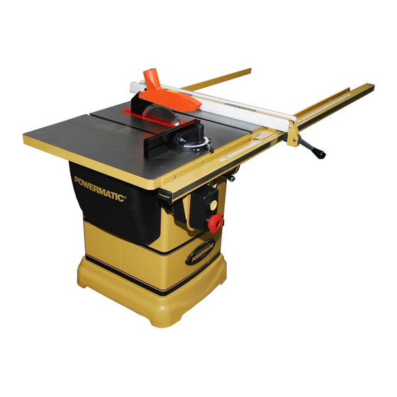
- Page 1 Operating Instructions and Parts Manual 10-inch Cabinet Saw Model PM1000 RU Powermatic 427 New Sanford Road LaVergne, Tennessee 37086 Part No. M-1791000 Ph.: 800-274-6848 Revision A 04/2014 www.powermatic.com...
-
Page 2: Warranty And Service
Warranty and Service Powermatic warrants every product it sells against manufacturers’ defects. If one of our tools needs service or repair, please contact Technical Service by calling 1-800-274-6846, 8AM to 5PM CST, Monday through Friday. Warranty Period The general warranty lasts for the time period specified in the literature included with your product or on the official Powermatic branded website. -
Page 3: Table Of Contents
2.0 Table of contents Section Page 1.0 Warranty and Service ....................錯誤! 尚未定義書籤。 2.0 Table of contents ............................3 3.0 Safety warnings .............................. 4 3.1 Kickback ..............................5 4.0 About this manual ............................6 5.0 Glossary ................................. 7 6.0 Specifications ..............................8 7.0 Setup and assembly ............................. -
Page 4: Safety Warnings
10. Do not operate this machine while tired or under the influence of drugs, alcohol or any medication. 11. Make certain machine properly 3.0 Safety warnings grounded. 12. Make all machine adjustments or maintenance Read and understand the entire owner’s with the machine unplugged from the power manual before... -
Page 5: Kickback
3.1 Kickback 25. Maintain tools with care. Keep blade sharp and clean for the best and safest performance. The most common accidents among table saw Follow instructions for lubricating and changing users, according to statistics, can be linked to accessories. kickback, the high-speed expulsion of material from 26. -
Page 6: About This Manual
JPW Industries, Inc., covering the safe operation and maintenance procedures for a Powermatic Model PM1000 Cabinet Saw. This manual contains instructions on installation, safety precautions, general operating procedures, maintenance instructions and parts breakdown. Your machine has been designed and constructed to provide years of trouble-free operation if used in accordance with the instructions as set forth in this document. -
Page 7: Glossary
5.0 Glossary Arbor: Metal shaft that connects the drive Parallel: Position of the rip fence equal in distance mechanism to the blade. at every point to the side face of the saw blade. Bevel Edge Cut: Tilt of the saw arbor and blade Perpendicular: 90°... -
Page 8: Specifications
6.0 Specifications Model number ..............................PM1000 Stock numbers: Saw unit only, without Accu-Fence or rail system ..............1791000M RU (230V) Saw unit only, without Accu-Fence or rail system ..............1791000T RU (400V) Saw with 30” Accu-Fence and rail system ....................1791000K Saw with 50” Accu-Fence and rail system ....................1791001K Motor and electricals: Motor type ................ - Page 9 Materials: Main table ............................ground cast iron Extension wings ..........................ground cast iron Trunnion ............................... cast iron Enclosed cabinet ..............................steel Table: Main table dimensions ....................20" L x 27" W (508 x 686 mm) Table dimensions with wings ..................40" L x 27" W (1016 x 686 mm) Table area in front of blade at maximum height ..................
-
Page 10: Setup And Assembly
7.1.2 Hardware package (Figure 2) 7.0 Setup and assembly Hex cap screws, M10x35 (HP-1) 7.1 Shipping contents Lock washers, M10 (HP-2) Flat washers, M10 (HP-3) 7.1.1 Carton contents (Figure 1) Socket head button screws, M6x16 (HP-4) Lock washers, M6 (HP-5) Cabinet saw Flat washers, M6 (HP-6) CE Type Guard assembly (A) (not shown) -
Page 11: Installing Handwheels And Hooks
Remove screws holding saw to pallet, by (Assembly Tip: If you are doing this without an unscrewing them from underneath pallet. assistant, lift extension wing vertically to table edge. Install center screw and washer, and Carefully slide saw from pallet onto floor. make snug. -
Page 12: Rails And Fence
7.10 Motor cover Shift extension wing so it is slightly above saw table surface. Refer to Figure 8. Begin by tightening the three screws (17mm At the motor side, slide hinge pins through motor wrench) under the extension wing that secure cover cylinders and into hinge barrels on saw. -
Page 13: Installing And Removing Blade
7.12 Installing and removing blade 7.13 Riving knife A blade is not provided with the PM1000. Refer to Figure 12. To install riving knife: Use care when working with or Remove table insert. around sharp saw blades to prevent injury. Raise blade arbor all the way up and set tilt to Refer to Figures 10 and 11. -
Page 14: Blade Guard
delay fuse marked “D”. Local codes take pawl block down until it securely engages in precedence over recommendations. notch. Allow pawls to drop freely to the table. 8.1 Grounding instructions 7.15 Blade guard 1. All Grounded, Cord-connected Tools: Refer to Figure 12. In the event of a malfunction or breakdown, grounding provides a path of least resistance for Push and hold button (J... -
Page 15: Magnetic Switch And Safety Key
9.0 Adjustments Do not rely that no light means no power to the machine. Always check for power first. Failure to comply may cause 9.1 Tools required for adjustments serious injury! Hex keys – 3, 4, and 8mm Referring to Figure 22: Wrenches –... -
Page 16: Blade Tilt Stop Adjustment
Verify that scale indicator (G) reads 0º. If further adjustment is needed: Loosen screw (F) and adjust indicator (G) until it reads 0º. Tighten screw (F). If the above procedure does not satisfactorily align the miter gauge, loosen two screws (J, Figure 18) beneath mounting block and shift block as needed. -
Page 17: Riving Knife Alignment
wrench, and turn set screw (B ) with a hex key the needed amount. Retighten nut (B Figure 19 Tilt blade with handwheel until square and Figure 22 blade are flush. 9.6 Riving knife alignment If adjustment is required, loosen nut (A Figure 20) on 90°... -
Page 18: Table To Blade Alignment
through openings located in the corners of the Remove blade guard, pawl, table insert and clamp plate (B, Figure 25). riving knife. Adjust any number of setscrews required to Use a 5mm hex key to loosen two socket head bring riving knife in alignment with saw blade. button screws (E, Figure 25). -
Page 19: Belt Adjustment
Push down on motor and tighten screw (C) to tension new belt. Retighten nut (D). Figure 28 Rotate marked tooth (A) so that it is slightly above table top at the rear and, using the square as before, verify that distance to blade is the same. - Page 20 Applying feed force when ripping to the Always keep your hands out of line of the cutoff (free) section of workpiece instead of saw blade and never reach back of the the section between saw blade and fence. cutting blade with either hand to hold the ...
- Page 21 If the work piece does not have a straight edge, nail an auxiliary straight edged board on it to provide one against the fence. To cut properly, the board must make good contact with the table. Do not attempt to cut warped boards. Figure 34 Figure 32 When ripping long boards, use a support at front of...
- Page 22 Do not crosscut workpieces shorter than 6". Before starting a cut, be sure the miter gauge is securely clamped at the desired angle. Hold the workpiece firmly against the table and back against the miter gauge. Always use the saw guard and riving knife and make sure the riving knife is properly aligned.
-
Page 23: Safety Devices
Never use a zero-clearance insert with saw blade in tilted position. Figure 41 The process of cutting 1/8" to 13/16" grooves in workpieces is accomplished by the use of a stacked dado blade set or an adjustable type blade mounted on the saw arbor. By using various combinations of stacked dado blades, or properly setting the dial on an adjustable blade, an accurate width dado can be made. - Page 24 Push stick and push block The use of a push block or push stick provides an added level of safety for the operator. A push stick is included with your table saw, but you may wish to make others personalized for different cutting procedures.
- Page 25 Figure 45 – Push stick template...
-
Page 26: Maintenance
Periodic: 12.0 Maintenance Keep the inside of the cabinet and trunnion area clean. Always disconnect power to Check for excessive play in the tilting and the machine before performing maintenance. raising mechanism and in the saw arbor and Failure to do this may result in serious adjust as required. -
Page 27: Optional Accessories
13.0 Optional accessories These accessory items (purchased separately) can enhance the functionality of your table saw. Contact your dealer to order, or call JPW at the phone number on the cover. # 708097 – Dado Insert Figure 46 # 708119 – Universal Mobile Base, adjustable up to 36” x 36” Figure 47 # 708158 –... -
Page 28: Troubleshooting The Pm1000 Cabinet Saw
14.0 Troubleshooting the PM1000 Cabinet Saw Table 2 Symptom Probable Cause Remedy Saw will not start. No incoming power. Check plug connection. Low voltage. Check power line for proper voltage. Open circuit motor loose Inspect all lead connections on motor for connection. -
Page 29: Replacement Parts
15.0 Replacement Parts Replacement parts are listed on the following pages. To order parts or reach our service department, call 1- powermatic .com). Having the 800-274-6848 Monday through Friday (see our website for business hours, www. Model Number and Serial Number of your machine available when you call will allow us to serve you quickly... -
Page 30: Pm1000 Table And Cabinet Assembly - Exploded View
15.1.1 PM1000 Table and Cabinet Assembly – Exploded View... -
Page 31: Pm1000 Table And Cabinet Assembly - Parts List
15.1.2 PM1000 RU Table and Cabinet Assembly – Parts List Index No Part No Description Size 1 ....1791789 ....Miter Gauge Assembly (index #2 thru 22) ..........1 2 ....PM2000-340 .... Handle ...................... 1 3 ....TS-0680031 ..... Flat Washer ............. 5/16” ......... 1 4 .... - Page 32 59 ..... PM1000-059 .... Tilt Angle Scale ..................1 60 ..... TS-1533032 ..... Pan Head Screw ..........M5 x 10 ......2 61 ..... PM2000-05 ....Powermatic Logo ..................1 62 ..... LM000636 ....Warning Label ..................1 63 .....
-
Page 33: Pm1000 Motor And Trunnion Assembly - Exploded View
15.2.1 PM1000RU Motor and Trunnion Assembly – Exploded View... -
Page 34: Pm1000 Motor And Trunnion Assembly - Parts List
15.2.2 PM1000RU Motor and Trunnion Assembly – Parts List Index No Part No Description Size 101 ... PM1000-101 .... Arbor Nut ....................1 102 ... PM1000-102 .... Arbor Collar ....................1 103 ... PM1000-103RU ..Blade ............... hole 30mm,Ø 255,40T ..1 104 ... - Page 35 Index No Part No Description Size 145 ... TS-1534041 ..... Pan Head Screw ..........M5 x 10 ......8 146 ... TS-1523011 ..... Socket Set Screw ..........M6 x 6 ......3 147 ... TS-0680042 ..... Flat Washer ............. 3/8” ........2 148 ...
-
Page 36: Pm1000 Blade Guard Assembly - Exploded View
15.3.1 PM1000RU Blade Guard Assembly – Exploded View 15.3.2 PM1000RU Blade Guard Assembly – Parts List Index No Part No Description Size ....PM1000-BGARU ..Blade Guard Assembly (index #1 thru 4) ..........1 1 ....PM1000-301RU ..Riving Knife ............. Thickness 0.1” ....1 2 .... -
Page 37: Electrical Connections For Pm1000
16.0 Electrical Connections for PM1000RU 2HP,230V,50Hz... - Page 38 3HP,400V,50Hz...
- Page 39 This page intentionally left blank.
- Page 40 JPW Industries, Inc., 427 New Sanford Road LaVergne, Tennessee 37086 Phone: 800-274-6848 www.powermatic.com...