Table of Contents
Advertisement
Quick Links
Advertisement
Table of Contents

Related Manuals for Powermatic 64B


Summary of Contents for Powermatic 64B
- Page 1 Operating Instructions and Parts Manual Accu-Fence and Rail System ® for 64A, 64B and PM1000 Table Saws Powermatic 427 New Sanford Road LaVergne, Tennessee 37086 Part No. M-2195075Z Ph.: 800-274-6848 Revision C3 01/2019 www.powermatic.com Copyright © 2017 Powermatic...
-
Page 2: Warranty And Service
1.0 Warranty and Service Powermatic warrants every product it sells against manufacturers’ defects. If one of our tools needs service or repair, please contact Technical Service by calling 1-800-274-6846, 8AM to 5PM CST, Monday through Friday. Warranty Period The general warranty lasts for the time period specified in the literature included with your product or on the official Powermatic branded website. -
Page 3: Table Of Contents
9.0 Appendix – Extension Table Dimensions .................... 15 The specifications in this manual are given as general information and are not binding. Powermatic reserves the right to effect, at any time and without prior notice, changes or alterations to parts, fittings, and accessory... -
Page 4: Safety Warnings
19. Keep visitors a safe distance from the work Fence is used for other than its intended area. Keep children away. use. If used for other purposes, Powermatic 20. Make your workshop child proof with disclaims any real or implied warranty and... - Page 5 28. Never leave machine running WARNING: Drilling, sawing, sanding or unattended. Turn the power off and do not machining wood products generates wood leave the machine until it comes to a dust and other substances known to the complete stop. State of California to cause cancer.
-
Page 6: Unpacking
4.0 Unpacking Open shipping cartons and check that all parts are intact. Report any damage immediately to your distributor. Read the instruction manual thoroughly for assembly, alignment, and maintenance instructions. 4.1 Carton contents Box One: (1) Accu-Fence (1) Lock lever knob (1) Owner’s manual (1) Warranty card Box Two: (refer to Figures 1 and 2) -
Page 7: Assembly
C-clamps, 4” or 6” The following instructions are for installing the Accu- Fence and Rail System on a Powermatic Model 64A, 64B or PM1000 Table Saw. The rails should bolt to the Powermatic saw without any drilling. 5.1 Front Rail Installation... -
Page 8: Back Rail Installation
The wood extension table (including the optional router table) sits flush against the saw table and along the inside of the rails. The Powermatic logo (or warning label on the router table) should face outward. The extension table is not bolted to the saw table, it is bolted only to the rails. -
Page 9: Guide Tube
Lay a straight edge across both extension table and saw table to ensure proper leveling. Tap down the extension table at various points along its edge where it meets the saw table, until it is level with the saw table (Figure 10). As one part of the edge becomes level with the table, tighten the clamp on that side. -
Page 10: Accu-Fence Installation
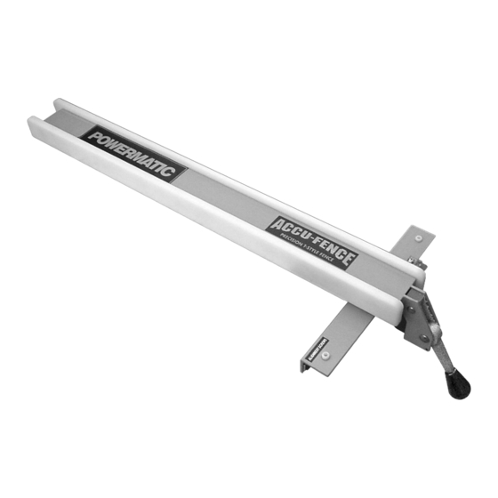
Press tube cap into opening of guide tube. Use a rubber mallet if needed to drive it on. The measurement scale will be applied to the guide tube in section 5.6.5, Scale Installation. 5.5 Accu-Fence installation Screw the lock lever knob into the threaded handle on the Accu-Fence, as shown in Figure 14. -
Page 11: Clamping Pressure
(Figure 17) until fence is 90 to table. Lock the fence and check the adjustment again. 5.6.5 Scale installation The measurement scale supplied with the 64B and PM1000 rail system is now shipped unattached, as each of these models requires a different scale Figure 19 position. -
Page 12: Cursor Adjustment
To order parts or reach our service department, call 1-800-274-6848 Monday through Friday (see our website for business hours, www.powermatic.com). Having the Model Number and Serial Number of your machine available when you call will allow us to serve you quickly and accurately. -
Page 13: Accu-Fence Assembly (64A/64B/Pm1000) - Parts List
1 ....HF2-101 ....Left Side Plate ....................1 2 ....AF-102 ...... Fence Body Assembly ................... 1 3 ....PM1000-10 ....Tube Cap, Powermatic .................. 1 4 ....HF2-104 ....Right Side Plate ..................... 1 5 .... -
Page 14: Accu-Fence Rail Assembly (64A/64B/Pm1000) - Parts List
9 ....AF-209 ...... Back Fence Rail – Standard Table ......30” ......... 1 ....AF-209A ....Back Fence Rail – Long Table......... 52” ......... 1 10 ....PM1000-10 ....Tube Cap, Powermatic .................. 2 11 ....HF2-211 ....Hardware Kit (Standard Table) – not shown ... 30" ......... 1 .... -
Page 15: Leg Assembly For Wood Extension Table (Optional)
5 ....XF2-305 ....Metal Insert .............. 30 x 30mm ....2 9.0 Appendix – Extension Table Dimensions The dimensions below are provided if you plan to build your own extension table instead of purchasing one that is available through Powermatic. - Page 16 427 New Sanford Rd. LaVergne, TN 37086 Phone: 800-274-6848 www.powermatic.com...