Table of Contents
Advertisement
Advertisement
Table of Contents
Troubleshooting

Related Manuals for Powermatic PM1800


Summary of Contents for Powermatic PM1800
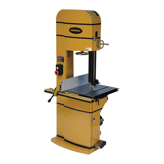
- Page 1 Operating Instructions and Parts Manual 18-inch Band Saw Model PM1800 WALTER MEIER (Manufacturing) Inc. 427 New Sanford Rd. LaVergne, TN 37086 Part No. M-1791800 Ph.: 800-274-6848 Revision A3 10/09 www.powermatic.com Copyright © 2009 Walter Meier (Manufacturing) Inc.
-
Page 2: Warranty And Service
This warranty covers only the initial purchaser of the product. WHAT IS THE PERIOD OF COVERAGE? The general POWERMATIC warranty lasts for the ti m e period specified in the product literature of each product. WHAT IS NOT COVERED? The Five Year Warranty does not cover products used for commercial, industrial or educational purposes. Products with a Five Year Warranty that are used for commercial, industrial or education purposes revert to a One Year Warranty. -
Page 3: Table Of Contents
Table of Contents Warranty and Service..........................2 Table of Contents ..........................3 Warning .............................5 Introduction ............................7 Specifications .............................7 Features and Terminology ........................8 Unpacking ............................9 Installation............................10 Assembly ............................10 Rear Rail ............................10 Front Rail and Guide Tube ......................11 Fence Assembly..........................11 Resaw Fence .......................... - Page 4 Replacement Parts ........................... 35 Upper Wheel Assembly – Exploded View..................36 Upper Wheel Assembly – Parts List ....................37 Lower Wheel and Motor Assembly – Exploded View ................ 38 Lower Wheel and Motor Assembly – Parts List ................39 Blade Guide Assembly – Exploded View ..................41 Blade Guide Assembly –...
-
Page 5: Warning
Warning 1. Read and understand the entire owner’s manual before attempting assembly or operation. 2. Read and understand the warnings posted on the machine and in this manual. Failure to comply with all of these warnings may cause serious injury. 3. -
Page 6: Save These Instructions
21. Make your workshop child proof with padlocks, master switches or by removing starter keys. 22. Give your work undivided attention. Looking around, carrying on a conversation and “horse-play” are careless acts that can result in serious injury. 23. Maintain a balanced stance at all times so that you do not fall or lean against the blade or other moving parts. -
Page 7: Introduction
Introduction This manual is provided by Walter Meier (Manufacturing) Inc., covering the safe operation and maintenance procedures for a Powermatic Model PM1800 Band Saw. This manual contains instructions on installation, safety precautions, general operating procedures, maintenance instructions and parts breakdown. This machine has been designed and constructed to provide years of trouble free operation if used in accordance with instructions set forth in this manual. -
Page 8: Features And Terminology
Features and Terminology Figure 1... -
Page 9: Unpacking
Contents of the Shipping Container Unpacking Band Saw (not shown) Open shipping container and check for shipping Rip Fence Body damage. Report any damage immediately to Extruded Aluminum Resaw Fence your distributor and shipping agent. Do not Front Rail discard any shipping material until the Band Saw Rear Rail is assembled and running properly. -
Page 10: Installation
Installation Tools required for assembly and set up: 7/32” hex (Allen) wrench 6mm hex (Allen) wrench 12mm open-end wrench Square Hoist or forklift, with straps Remove all crating and plastic from around the machine. Remove any screws or straps holding the band saw to the shipping pallet. -
Page 11: Front Rail And Guide Tube
The measurement should be the same at both ends of the rear rail. Adjust as needed. 3. Tighten the two screws with a 12mm wrench. Front Rail and Guide Tube Refer to Figure 6. 4. Install the front rail to the front edge of the table, using two 5/16-18 x 3/4 hex cap screws (AA), two 5/16 lock washers (BB), Figure 6... -
Page 12: Fence To Table Clearance
Fence to Table Clearance 1. Check the clearance between the table and the bottom of the fence (Figure 10). The fence should not rub against the table surface but be slightly above it. This gap should be the same at the front of the table as it is at the back. -
Page 13: Setting Fence Parallel To Blade
4. Use a gauge to carefully measure the distance from miter slot to straight edge. Take measurements at both front and back of table – these should be the same. 5. If the miter slot is not parallel to the blade, loosen the four hex cap screws that secure the table to the trunnion (Figure 14 shows three of them), and shift the table as needed... -
Page 14: Dust Collection
Dust Collection The use of a dust collection system is strongly recommended for this band saw. It will help keep the shop clean, as well as reduce potential health hazards caused by inhalation of wood dust. The collector should have a capacity sufficient for this size machine –... -
Page 15: Extension Cords
Recommended Gauges (AWG) of Extension Cords Extension Cords Extension Cord Length * The use of extension cords is discouraged; try to position the machine within reach of the power source. extension cord becomes Amps feet feet feet feet feet feet necessary, make sure the cord rating is suitable <... -
Page 16: Installing/Changing Blades
New blades are usually packaged in a coiled position; to prevent injury uncoil them slowly and carefully, while wearing work gloves and safety glasses. The PM1800 Band Saw is designed for blades from 1/16” to 1-1/2” wide. The Band Saw is provided with... -
Page 17: Blade Tension
8. Guide new blade through table slot. Place blade loosely in the upper and lower blade guides. Make sure blade teeth point down toward table, and toward the front of the saw. (If the teeth will not point down, no matter how you orient the blade, then the blade is twisted inside-out. -
Page 18: Blade Tracking
Blade Tracking Refer to Figure 26. After being properly tensioned, the blade must be tracked. “Tracking” refers to the position of the blade on the wheels while the machine is in operation. Tracking should checked periodically, and is mandatory after every blade change. -
Page 19: Upper Blade Guides
9. Make further adjustments as needed, with the saw disconnected from power. Upper Blade Guides The bearing guides should be set so that contact between blade and guides will occur only when the blade is under pressure from a workpiece. To adjust the upper bearing guides for proper blade control, proceed as follows. -
Page 20: Upper Thrust Bearing
Upper Thrust Bearing Refer to Figures 29 and 32: The thrust bearing prevents backward deflection of the blade during cutting. The thrust bearing has three options for stabilizing the back of the blade (see Figure 32). The v-shaped groove is for small, thin blades, such as scrolling and contour-cutting blades. -
Page 21: Guide Post
Guide Post Refer to Figure 34. 1. Disconnect band saw from power source. 2. Loosen lock handle (A) and raise or lower guide post by rotating the handwheel (B). 3. Position the blade guide assembly so that the bottom of the guide bearings are about 3/16”... -
Page 22: Resaw Pin
Resaw Pin Refer to Figure 35. A resaw pin is provided with the band saw. It provides a single contact point while ripping a workpiece into thinner boards. Remove the aluminum resaw fence and mount the resaw pin to the slot in the fence body, securing it with the knob, as shown. -
Page 23: Blade Speed Adjustment
The 45° stops can be checked in similar fashion, using an angle gauge similar to that shown in Figure 37. To adjust the miter gauge angle for operations: 1. Loosen the handle (A). 2. Rotate the gauge body until the pointer (B) lines up with the desired angle on the scale. -
Page 24: Wheel Brush
2. Open the upper and lower doors and remove the blade. 3. Unscrew the hex nut from the lower wheel shaft and remove the lower wheel. 4. Loosen the motor lock handle. 5. Raise the motor lift handle and re-tighten motor lock handle to hold motor in raised position. -
Page 25: Safety Key
Do not rely that no light means no power to the machine. Always check for power first. Failure to comply may cause serious injury! Refer to Figure 42: Start – Press the green start switch. When power is connected to the machine, the green light is always on regardless of whether the Band Saw is running or not. -
Page 26: Operation
Ripping Operation Ripping cutting lengthwise down The following section contains basic information, workpiece, and with the grain (of wood stock). and is not intended to cover all possible See Figure 44. Always use a push stick or applications or techniques using the Band Saw. similar device when ripping narrow pieces. -
Page 27: Resawing
Resawing Resawing is the process of slicing stock to reduce its thickness, or to produce boards that are thinner than the original workpiece, such as veneers. The ideal blade for resawing is the widest one the machine can handle, as the wider the blade the better it can hold a straight line. - Page 28 Maintenance Before doing maintenance on the machine, disconnect it from the electrical supply by pulling out the plug or switching off the main switch! Failure to comply may cause serious injury. Clean the band saw regularly to remove any resinous deposits and sawdust. Keep the miter slot, and the guide bearings, clean and free of resin.
-
Page 29: Blade Selection
Blade Selection Using the proper blade for the job will increase the operating efficiency of your band saw, help reduce necessary maintenance, improve your productivity. Thus, it is important to follow certain guidelines when selecting a saw blade. Here are factors to consider when selecting a blade: •... -
Page 30: Set
Material Band saw blades can be made from different types of metals. The most common include spring steel, carbon steel, bimetal (alloy steel equipped with a high speed cobalt steel edge welded to it), or carbide tips. Because of the importance of blade selection, it is recommended that you use the blade selection guide on page 31. -
Page 31: Blade Selection Guide
Blade Selection Guide Identify the material and thickness of your workpiece. The chart will show the recommended PITCH, blade TYPE, and FEED RATE. Key: H – Hook L – Low S – Skip M – Medium R – Regular H – High Example: 10/H/M means 10 teeth per inch / Hook Type Blade / Medium Feed For Radius Cutting Study the part drawing or prototype, or actually... -
Page 32: Troubleshooting - Operational Problems
Troubleshooting – Operational Problems Trouble Probable Cause Remedy Table tilt does not Locking lever is not tight. Tighten locking lever (A, Figure 20). hold position under Trunnion locking mechanism is load. Replace trunnion locking mechanism. broken or worn. Table will not tilt. Trunnion is not lubricated. - Page 33 Trouble Probable Cause Remedy Blade forms cracks at Replace with proper blade for job. Teeth not suitable for particular job, or base of teeth. are incorrectly set. Blade thickness not suitable for band Replace with proper thickness blade. wheel diameter. Blade sharpened incorrectly, Sharpen blade properly or replace.
-
Page 34: Troubleshooting - Mechanical And Electrical Problems
Troubleshooting – Mechanical and Electrical Problems Trouble Probable Cause Remedy Machine will not Verify machine is connected to power start/restart or No incoming power. source, and that the safety key is repeatedly trips installed on the switch. circuit breaker or Cord damaged. -
Page 35: Replacement Parts
Replacement parts are listed on the following pages. To order parts or reach our service department, call 1-800-274-6848, Monday through Friday (see our website for business hours, www.powermatic.com). Having the Model Number and Serial Number of your machine available when you call will allow us to... -
Page 36: Upper Wheel Assembly - Exploded View
Upper Wheel Assembly – Exploded View... -
Page 37: Upper Wheel Assembly - Parts List
15 .... JWBS20-542 ...Door Stud................... 1 16 .... TS-0561011 ....Hex Nut............1/4-20 ......1 17 .... JWBS20QT-511 ..Bracket Shaft..................1 18 .... PM1800-118....Socket Head Button Screw ........3/8-16x3/4 ....8 19 .... JWBS20QT-519 ..Plate ....................2 20 .... JWBS20QT-520 ..Support Bracket .................. 2 21 .... -
Page 38: Lower Wheel And Motor Assembly - Exploded View
Lower Wheel and Motor Assembly – Exploded View... -
Page 39: Lower Wheel And Motor Assembly - Parts List
24 .... PM1800-224....Lock Knob ..................1 25 .... TS-081C052 ....Phillips Pan Head Machine Screw......#10-24x3/4 ....1 26 .... PM1800-226....Lower Dust Chute ................1 27 .... PM1800-227....Socket Head Button Screw ........5/16-18x1 ....2 28 .... PM1800-134....Handle ....................1 29 .... PM1800-229....Motor Protector Plate ................1 30 .... - Page 40 78 .... PM1800-278....Key ..............7x7x60 ....... 1 79 .... TS-0680091 ....Flat Washer............3/4 ......1 80 .... TS-0051071 ....Hex Cap Screw ..........5/16-18x1-1/2 ..... 1 81 .... PM1800-281....Wire for Limit Switch (not shown) ............1 82 .... PM1800-BA .....Brake Assembly (index # 42,44,45,57,59,60,62,63,64) ......1...
-
Page 41: Blade Guide Assembly - Exploded View
Blade Guide Assembly – Exploded View Lower Bearing Guide Upper Bearing Guide... -
Page 42: Blade Guide Assembly - Parts List
8 ....JWBS20-349 ...Thumb Knob ..................3 9 ....TS-1521011 ....Socket Set Screw ..........M4x4 ......8 10 .... PM1800-310....C-Ring .............S-10......2 11 .... PM1800-311....Retaining Ring ..........R-26 ......2 12 .... BB-6000ZZ ....Ball Bearing............6000ZZ ...... 2 13 .... PM1800-313....Bearing Holder ................... 2 14 .... - Page 43 66 .... JWBS20-339 ...Threaded Lock Bushing ..............1 67 .... JWBS18DX-337 ..Bracket ....................1 68 .... JWBS20-340 ...Bolt ....................1 69 .... PM1800-369....Bearing Support Shaft ................. 1 70 .... PM1800-370....Sliding Plate ..................1 71 .... PM1800-371....Upper Guide Bracket ................1...
-
Page 44: Table And Fence Assembly – Exploded View
Table and Fence Assembly – Exploded View... -
Page 45: Table And Fence Assembly – Parts List
25 .... TS-0680021 ....Flat Washer............1/4 ......5 26 .... TS-0720071 ....Lock Washer ............1/4 ......1 27 .... PM1800-427A ..Table (for serial no. 081218000016 and higher) ........1 ....PM1800-427....Table (for serial no. 081218000015 and lower) ........1 28 .... PM1800-428....Aluminum Resaw Fence ..............1 29 .... - Page 46 99 .... TS-0810012 ....Slotted Round Head Machine Screw ....#10-24x1/4 ....2 100 ..PM1800-FA .....Fence Assembly (index # 1 thru 26, 28, and 80) ........1 101 ..PM1800-MGA..Miter Gauge Assembly (index # 32, 49, and 51 thru 62) ......1...
-
Page 47: Electrical Connections - 5Hp 1Ph 230V
Electrical Connections – 5HP 1PH 230V Magnetic Switch Electrical Board WHITE YELLOW BLACK 400MFD 250VAC 50uF 450WVAC Motor... -
Page 48: Electrical Connections - 5Hp 3Ph 230V
Electrical Connections – 5HP 3PH 230V Magnetic Switch Electrical Board WHITE YELLOW BLACK Motor... -
Page 49: Electrical Connections - 5Hp 3Ph 460V
Electrical Connections – 5HP 3PH 460V Magnetic Switch Electrical Board WHITE YELLOW BLACK Motor... - Page 50 NOTES...
- Page 52 WALTER MEIER (Manufacturing) Inc. 427 New Sanford Rd. LaVergne, TN 37086 Phone: 800-274-6848 www.powermatic.com www.waltermeier.com...