Table of Contents
Advertisement
Quick Links
Advertisement
Table of Contents

Related Manuals for Powermatic 1791000K


Summary of Contents for Powermatic 1791000K
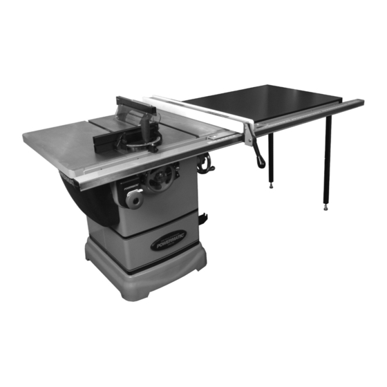
- Page 1 This .pdf document is bookmarked Operating Instructions and Parts Manual 10-inch Cabinet Saw Model PM1000 Powermatic 427 New Sanford Road LaVergne, Tennessee 37086 Part No. M-1791000 Ph.: 800-274-6848 Revision B 01/2019 www.powermatic.com Copyright © 2015 Powermatic...
-
Page 2: Warranty And Service
1.0 Warranty and Service Powermatic warrants every product it sells against manufacturers’ defects. If one of our tools needs service or repair, please contact Technical Service by calling 1-800-274-6846, 8AM to 5PM CST, Monday through Friday. Warranty Period The general warranty lasts for the time period specified in the literature included with your product or on the official Powermatic branded website. -
Page 3: Table Of Contents
2.0 Table of contents Section Page 1.0 Warranty and Service ............................. 2 2.0 Table of contents ............................3 3.0 Safety warnings .............................. 4 3.1 Kickback ..............................5 4.0 About this manual ............................6 5.0 Glossary ................................. 7 ... -
Page 4: Safety Warnings
If used for other purposes, 20. Give your work undivided attention. Looking Powermatic disclaims any real or implied around, carrying on a conversation and “horse- warranty and holds itself harmless from any play”... -
Page 5: Kickback
3.1 Kickback 28. Do not attempt to saw long or wide boards unsupported where spring or weight could The most common accidents among table saw cause the board to shift position. users, according to statistics, can be linked to 29. Always use the riving knife, blade guard, push kickback, the high-speed expulsion of material from stick and other safety devices for all operations the table that can strike the operator. -
Page 6: About This Manual
Additional knowledge can be obtained from experienced users or trade articles. Whatever accepted methods are used, always make personal safety a priority. If there are questions or comments, please contact your local supplier or Powermatic. Powermatic can also be reached at our web site: www.powermatic.com. -
Page 7: Glossary
5.0 Glossary Arbor: Metal shaft that connects the drive Parallel: Position of the rip fence equal in distance mechanism to the blade. at every point to the side face of the saw blade. Bevel Edge Cut: Tilt of the saw arbor and blade Perpendicular: 90°... -
Page 8: Specifications
Model number ..............................PM1000 Stock numbers: Saw unit only, without Accu-Fence or rail system ..................1791000 Saw with 30” Accu-Fence and rail system ....................1791000K Saw with 50” Accu-Fence and rail system ....................1791001K Motor and electricals: Motor type ................totally enclosed fan cooled, induction, capacitor start Horsepower .............................. - Page 9 L=length; W=width; D=depth; H=height The specifications in this manual were current at time of publication, but because of our policy of continuous improvement, Powermatic reserves the right to change specifications at any time and without prior notice, without incurring obligations.
-
Page 10: Setup And Assembly
7.1.2 Hardware package (Figure 2) 7.0 Setup and assembly Hex cap screws, M10x35 (HP-1) Lock washers, M10 (HP-2) 7.1 Shipping contents Flat washers, M10 (HP-3) 7.1.1 Carton contents (Figure 1) Socket head button screws, M6x16 (HP-4) Lock washers, M6 (HP-5) Cabinet saw Flat washers, M6 (HP-6) Guard assembly (A) -
Page 11: Installing Handwheels And Hooks
Remove screws holding saw to pallet, by make snug. Then pivot wing parallel to saw unscrewing them from underneath pallet. table to insert remaining two screws.) Carefully slide saw from pallet onto floor. The cabinet saw should be placed in an area with a sturdy level floor, good ventilation and sufficient lighting. -
Page 12: Rails And Fence
Shift extension wing so it is slightly above saw 7.9 Wood Extension Table table surface. For instructions on mounting the accessory wood Begin by tightening the three screws (17mm extension table, consult Accu-Fence manual, wrench) under the extension wing that secure document no. -
Page 13: Installing And Removing Blade
Figure 9 NOTE: If while lowering blade, the points on the anti-kickback pawls tend to catch in the seam between table and table insert, slightly raise that area of table insert above main table surface. Figure 11 (blade not provided) 7.12 Installing and removing blade 7.13 Riving knife A blade is not provided with the PM1000. -
Page 14: Anti-Kickback Pawls
Riving knife must be parallel to saw blade. See 8.0 Electrical connections section 9.6 for inspection and adjustments. The PM1000 table saw is rated at 115/230V power, NOTE: A low-profile riving knife is also provided, and is pre-wired for 115 volt. The table saw comes for making non-through cuts on the table saw. -
Page 15: Voltage Conversion
2. Grounded, cord-connected tools intended for 8.3 Overload reset button use on a supply circuit having a nominal rating less than 150 volts: If saw becomes overloaded and the motor shuts off, open motor cover and push reset button (B, This tool is intended for use on a circuit that has an Figure 14) to restart. -
Page 16: Adjustments
Do not rely that no light means no power to the machine. Always check for power first. Failure to comply may cause serious injury. To start saw, pull red button. Push it back in to stop saw. The switch has a safety key (Figure 15). Slide key out and store in a safe place, to prevent Figure 16 unauthorized starting of saw. -
Page 17: Blade Tilt Stop Adjustment
9.4.3 Extension plate screws (4mm hex key) to eliminate any play between bar and miter slot. The extension plate (D, Figure 17) can be adjusted by sliding to the right or left or removed entirely. 9.5 Blade tilt stop adjustment To adjust, loosen two lock handles (E), slide the The stops for 90°, 45°... -
Page 18: Riving Knife Alignment
Figure 23 Figure 21 The saw blade and riving knife must be in line. If adjustment is needed: 9.5.2 Tilt stop 45° Pull quick-release lever (A, Figure 24) and Repeat steps 1 through 4 above for 45° setting, as remove riving knife, making note as to which shown in Figure 22. -
Page 19: Belt Adjustment
9.6.2 Blade proximity alignment Raise miter gauge slightly out of its slot to serve as a shoulder. Using a sliding square (B) The gap between saw blade and riving knife must against the side of the bar, slide the scale over be between 3 and 8mm (Figure 26). -
Page 20: Arbor/Arbor Bearing Removal
Press down on motor while retightening screw Listed below are conditions which can cause (C). kickbacks: If belt shows signs of wear, fraying, cracks, etc. it Confining cutoff piece when should be replaced, as follows. crosscutting or ripping. Releasing workpiece before completing ... - Page 21 accidents. Never use a cracked saw blade. is properly aligned. When wood is cut along the grain, the kerf tends to close and bind on the blade The use of a sharp, well maintained, and and kickbacks can occur. correct cutting tool for the operation will help avoid injuries.
- Page 22 use the same side of the board against the fence for both cuts. Figure 33 Figure 35 10.4 Crosscutting Crosscutting is where the workpiece is fed cross grain into the saw blade using the miter gauge to support and position the workpiece (Figure 36). Figure 34 When ripping long boards, use a support at front of table (C, Figure 34), such as a roller stand, and a...
- Page 23 Length stops should not be used on the free end of Never use a zero-clearance the workpiece in the cutoff area. insert with saw blade in tilted position. Do not crosscut workpieces shorter than 6". Before starting a cut, be sure the miter gauge is securely clamped at the desired angle.
-
Page 24: Safety Devices
Figure 41 The process of cutting 1/8" to 13/16" grooves in workpieces is accomplished by the use of a stacked dado blade set or an adjustable type blade mounted on the saw arbor. By using various combinations of stacked dado blades, or properly setting the dial on an adjustable blade, an accurate width dado can be made. - Page 25 Push stick and push block The use of a push block or push stick provides an added level of safety for the operator. A push stick is included with your table saw, but you may wish to make others personalized for different cutting procedures.
-
Page 26: Maintenance
12.0 Maintenance Periodic: Keep the inside of the cabinet and trunnion area clean. Always disconnect power to the machine before performing maintenance. Check for excessive play in the tilting and Failure to do this may result in serious raising mechanism and in the saw arbor and personal injury. -
Page 27: Optional Accessories
13.0 Optional accessories These accessory items (purchased separately) can enhance the functionality of your table saw. Contact your dealer to order, or call Powermatic at the phone number on the cover. Figure 46 # 708097 – Dado Insert Figure 47 # 708119 –... -
Page 28: Troubleshooting The Pm1000 Cabinet Saw
14.0 Troubleshooting the PM1000 Cabinet Saw Table 2 Symptom Probable Cause Remedy Saw will not start. No incoming power. Check plug connection. Low voltage. Check power line for proper voltage. Open circuit motor loose Inspect all lead connections on motor for connection. -
Page 29: Replacement Parts
Number of your machine available when you call will allow us to serve you quickly and accurately. Non-proprietary parts, such as fasteners, can be found at local hardware stores, or may be ordered from Powermatic. Some parts are shown for reference only, and may not be available individually. ... -
Page 30: Pm1000 Table And Cabinet Assembly - Exploded View
15.1.1 PM1000 Table and Cabinet Assembly – Exploded View 31A(optional) 9 10 38-1 ... -
Page 31: Pm1000 Table And Cabinet Assembly - Parts List
15.1.2 PM1000 Table and Cabinet Assembly – Parts List Index No Part No Description Size 1 ....1791789 ....Miter Gauge Assembly (index #2 thru 22) ............. 1 2 ....PM2000-340 ....Handle ......................1 3 ....TS-0680031 ....Flat Washer ............. 5/16” ......1 4 .... - Page 32 59 ....PM1000-059 ....Tilt Angle Scale ....................1 60 ....TS-1533032 ....Pan Head Screw ............M5 x 10 ......2 61 ....PM2000-05 ....Powermatic Logo ................... 1 62 ....LM000636 ....Warning Label ....................1 63 ....
-
Page 33: Pm1000 Motor And Trunnion Assembly - Exploded View
15.2.1 PM1000 Motor and Trunnion Assembly – Exploded View ... -
Page 34: Pm1000 Motor And Trunnion Assembly - Parts List
15.2.2 PM1000 Motor and Trunnion Assembly – Parts List Index No Part No Description Size 101 .... PM1000-101 ....Arbor Nut ....................... 1 102 .... PM1000-102 ....Arbor Collar ....................1 104 .... PM1000-104 ....Arbor ......................1 105 .... - Page 35 Index No. Part No. Description Size 151 .... PM1000-151 ....Tilting Shaft ....................1 152 .... PM1000-152 ....Eccentric Bushing ..................1 153 .... TS-2342141 ....Hex Nut ..............M14 ....... 1 154 .... PM1000-154 ....Collar ......................2 155 ....
-
Page 36: Pm1000 Blade Guard Assembly - Exploded View
15.3.1 PM1000 Blade Guard Assembly – Exploded View ... -
Page 37: Pm1000 Blade Guard Assembly - Parts List
15.3.2 PM1000 Blade Guard Assembly – Parts List Index No Part No Description Size 1 ....PM1000-301 ....Riving Knife ....................1 1A ....PM1000-301A ... Low Profile Riving Knife ........... 0.1” Thk ......1 1B ....1791793 ....Low Profile Thin Kerf Riving Knife (Optional) ..0.079” Thk ..... 1 .... -
Page 38: Electrical Connections For Pm1000
16.0 Electrical Connections for PM1000 ... - Page 39 This page intentionally left blank. ...
- Page 40 427 New Sanford Road LaVergne, Tennessee 37086 Phone: 800-274-6848 www.powermatic.com ...