Siemens SIMATIC ET 200SP Manual
Digital output module f-dq 8x24vdc/0.5a pp hf (6es7136-6dc00-0ca0)
Hide thumbs
Also See for SIMATIC ET 200SP:
- System manual (320 pages) ,
- Manual (270 pages) ,
- Operating instructions manual (166 pages)
Table of Contents
Advertisement
SIMATIC
ET 200SP
Digital output module
F-DQ 8x24VDC/0.5A PP HF
(6ES7136-6DC00-0CA0)
Manual
Original operating instructions
05/2017
A5E38578424-AA
___________________
Preface
___________________
Documentation guide
___________________
Product overview
___________________
Connecting
___________________
Parameters/address space
___________________
Applications of the
F-I/O module
___________________
Interrupts/diagnostic
messages
___________________
Technical specifications
___________________
Response times
___________________
Switching of loads
1
2
3
4
5
6
7
A
B
Advertisement
Table of Contents

Related Manuals for Siemens SIMATIC ET 200SP


Summary of Contents for Siemens SIMATIC ET 200SP
- Page 1 ___________________ Preface ___________________ Documentation guide ___________________ SIMATIC Product overview ___________________ Connecting ET 200SP Digital output module ___________________ F-DQ 8x24VDC/0.5A PP HF Parameters/address space (6ES7136-6DC00-0CA0) ___________________ Applications of the F-I/O module Manual ___________________ Interrupts/diagnostic messages ___________________ Technical specifications Original operating instructions ___________________ Response times ___________________...
- Page 2 Note the following: WARNING Siemens products may only be used for the applications described in the catalog and in the relevant technical documentation. If products and components from other manufacturers are used, these must be recommended or approved by Siemens. Proper transport, storage, installation, assembly, commissioning, operation and maintenance are required to ensure that the products operate safely and without any problems.
-
Page 3: Preface
Standards You can find a dated reference to the respective standards in the certificate (https://support.industry.siemens.com/cs/ww/en/view/57141281) or in the EC Declaration of Conformity (https://support.industry.siemens.com/cs/ww/en/view/71764057) for the F-module. Digital output module F-DQ 8x24VDC/0.5A PP HF (6ES7136-6DC00-0CA0) - Page 4 In order to protect plants, systems, machines and networks against cyber threats, it is necessary to implement – and continuously maintain – a holistic, state-of-the-art industrial security concept. Siemens’ products and solutions only form one element of such a concept. Customer is responsible to prevent unauthorized access to its plants, systems, machines and networks.
-
Page 5: Table Of Contents
Table of contents Preface ..............................3 Documentation guide ..........................7 Product overview ..........................11 Properties ..........................11 Connecting ............................14 Wiring and block diagram ....................... 14 Parameters/address space ........................16 Parameters ..........................16 Explanation of parameters ...................... 18 4.2.1 F-parameters .......................... 18 4.2.1.1 F-parameters .......................... - Page 6 Table of contents Response times ............................ 50 Switching of loads ..........................51 Connecting capacitive loads ....................51 Switching of inductive loads ....................53 Digital output module F-DQ 8x24VDC/0.5A PP HF (6ES7136-6DC00-0CA0) Manual, 05/2017, A5E38578424-AA...
-
Page 7: Documentation Guide
Documentation guide The documentation for the SIMATIC ET 200SP distributed I/O system is arranged into three areas. This arrangement enables you to access the specific content you require. Basic information The system manual describes in detail the configuration, installation, wiring and commissioning of the SIMATIC ET 200SP. - Page 8 You can download the product information free of charge from the Internet (https://support.industry.siemens.com/cs/us/en/view/73021864). Manual Collection ET 200SP The Manual Collection contains the complete documentation on the SIMATIC ET 200SP distributed I/O system gathered together in one file. You can find the Manual Collection on the Internet (http://support.automation.siemens.com/WW/view/en/84133942).
- Page 9 ● Manuals, characteristics, operating manuals, certificates ● Product master data You can find "mySupport" - CAx Data in the Internet (http://support.industry.siemens.com/my/ww/en/CAxOnline). Application examples The application examples support you with various tools and examples for solving your automation tasks. Solutions are shown in interplay with multiple components in the system - separated from the focus in individual products.
- Page 10 You can find the SIMATIC Automation Tool on the Internet (https://support.industry.siemens.com/cs/ww/en/view/98161300). PRONETA With SIEMENS PRONETA (PROFINET network analysis), you analyze the plant network during commissioning. PRONETA features two core functions: ● The topology overview independently scans PROFINET and all connected components.
-
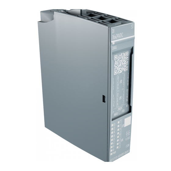
Page 11: Product Overview
Product overview Properties Article number 6ES7136-6DC00-0CA0 View of the module ① ⑦ Module type and name Function class ② ⑧ LED for diagnostics Color identification module type ③ ⑨ 2D matrix code Function and firmware version ④ ⑩ Connection diagram Color code to select the color identification labels ⑤... - Page 12 Product overview 2.1 Properties Properties The module has the following technical characteristics: ● Fail-safe digital module ● PROFIsafe ● Supports the "RIOforFA-Safety“ profile on F-CPUs S7-1200/1500. ● PROFIsafe address type 2 ● 8 outputs, PP-switching (SIL3/Cat.4/PLe) ● Supply voltage L+ ●...
- Page 13 ● Shield connection ● Electronic coding element as spare part You can find additional information about accessories in the Distributed I/O System ET 200SP System Manual (http://support.automation.siemens.com/WW/view/en/58649293). Passivation of fail-safe outputs over a long period of time WARNING Unintentional activation of F-I/O with fail-safe outputs If an F-I/O with fail-safe outputs is passivated for a period longer than that specified in the safety parameters (>...
-
Page 14: Connecting
Applications of the F-I/O module (Page 26) or Parameters/address space (Page 16). You can find additional information about wiring BaseUnits in the Distributed I/O System ET 200SP System Manual (http://support.automation.siemens.com/WW/view/en/58649293). Note The load group of the F-module must begin with a light-colored BaseUnit. Keep this in mind as well during configuration. - Page 15 Connecting 3.1 Wiring and block diagram Block diagram The following figure shows the wiring of the F-DQ 8×24VDC/0.5A PP HF digital output module on BaseUnit BU type A0 without AUX terminals. ① Backplane bus interface Ground for connection of actuator of channel n. ②...
-
Page 16: Parameters/Address Space
Parameters/address space Parameters Parameters for F-DQ 8x24VDC/0.5A PP HF WARNING Diagnostics functions should be activated or deactivated in accordance with the application, see section Applications of the F-I/O module (Page 26). The following parameters are possible: Table 4- 1 Configurable parameters Parameters Value range Default... - Page 17 Parameters/address space 4.1 Parameters Parameters Value range Default Parameter Scope reassignment in DQ parameters: Maximum test period 1000 s Module 100 s • 1000 s • Disable dark test for 48 hours disabled Module disable • enable • Channel parameters: Channel n Activated enabled...
-
Page 18: Explanation Of Parameters
You can find information on F-parameters for the F-monitoring time, the PROFIsafe address assignment (F-source address, F-destination address) and the F I/O DB in the manual SIMATIC Safety - Configuring and Programming (http://support.automation.siemens.com/WW/view/en/54110126). 4.2.1.2 Behavior after channel fault This parameter is used to specify whether the entire F-module is passivated or just the faulty channel(s) in the event of channel faults: ●... -
Page 19: Parameters Of The Channels
Parameters/address space 4.2 Explanation of parameters Use in S7-1500 F-CPUs When using the fail-safe module in S7-1500 F-CPUs, you set this parameter in the STEP 7 dialog of the fail-safe module: ● "Adjustable" ● "All channels automatically" ● "All channels manually" If you have set the "Behavior after channel fault"... -
Page 20: Activated
Parameters/address space 4.2 Explanation of parameters 4.2.2.3 Activated The channel is always activated for this F-module. 4.2.2.4 Max. readback time dark test Function Dark tests are shutdown tests with bit pattern test. For a dark test, a test signal is switched to the output channel while the output channel has the 1-signal. - Page 21 Parameters/address space 4.2 Explanation of parameters Setting readback time dark test Because the fault reaction time is extended by the length of the readback time dark test, we recommend that you set the readback time dark test as low as possible, but high enough that the output channel is not passivated.
-
Page 22: Max. Readback Time Light Test
Parameters/address space 4.2 Explanation of parameters Test pulses of the dark test The interval between two test pulses is 500 ms. Output of test pulses only during test cycle. Figure 4-2 Test pulses of the dark test Note If the dark test detects an error, the affected channel is switched off with the error message "Short circuit to L+", all the other channels with the error message "Safety-related shutoff". -
Page 23: Activated Light Test
Parameters/address space 4.2 Explanation of parameters If the signal was not read back correctly once the maximum readback time light test has expired, the output channel is passivated. No new process values are switched to the output channels while a bit pattern is still active (switch test is carried out). -
Page 24: Channel Failure Acknowledge
There you set the corresponding property at the F-I/O DB by means of the ACK_NEC tag. For detailed information about the F-I/O DB, refer to the SIMATIC Safety – Configuring and Programming (http://support.automation.siemens.com/WW/view/en/54110126) manual. Address space Address assignment of the digital output module F-DQ 8x24VDC/0.5A PP HF The digital output module F-DQ 8x24VDC/0.5A PP HF occupies the following address areas... - Page 25 F-modules and F-CPU in accordance with PROFIsafe. Additional information For detailed information about F-I/O access, refer to the SIMATIC Safety – Configuring and Programming (http://support.automation.siemens.com/WW/view/en/54110126) manual. See also Value status (Page 46) Digital output module F-DQ 8x24VDC/0.5A PP HF (6ES7136-6DC00-0CA0)
-
Page 26: Applications Of The F-I/O Module
You achieve SIL3/Cat.4/PLe with the following applications. The wiring is performed on the suitable BaseUnit. For more on this, see Connecting section in the system manual Distributed I/O System ET 200SP (http://support.automation.siemens.com/WW/view/en/58649293). Installation of the ground line between the power supply and the BaseUnit... -
Page 27: Application: Wiring A Load To Each Digital Output
Applications of the F-I/O module 5.2 Application: Wiring a load to each digital output Application: Wiring a load to each digital output Each of the 8 fail-safe digital outputs consists of two P-switches, which form a PP-switch DQ-PP . You connect the load between the sourcing output DQ-PP and ground. - Page 28 Applications of the F-I/O module 5.2 Application: Wiring a load to each digital output WARNING In order to achieve SIL3/Cat.4/PLe with this wiring, you must install a suitably-qualified actuator, for example in accordance with IEC 60947. WARNING The actuator can no longer be shut down if a cross circuit has developed between positive potential (e.g.
-
Page 29: Application: Wiring Two Loads In Parallel To Each Digital Output
Applications of the F-I/O module 5.3 Application: Wiring two loads in parallel to each digital output Application: Wiring two loads in parallel to each digital output The ground may be the internal ground M or an external ground. This circuit achieves SIL3/Cat.4/PLe. - Page 30 Applications of the F-I/O module 5.3 Application: Wiring two loads in parallel to each digital output WARNING The actuator can no longer be shut down if a cross circuit has developed between positive potential (e.g. L+) and DQ-PP . To prevent cross-circuits between positive potential (e.g. L+) and DQ-PP , you must route the lines used to connect the actuators in a cross-circuit- proof manner (for example, as separate, sheathed cables or in separate cable ducts).
-
Page 31: Application: Connection Of A Fail-Safe Digital Input To Each Digital Output
Applications of the F-I/O module 5.4 Application: Connection of a fail-safe digital input to each digital output Application: Connection of a fail-safe digital input to each digital output Each of the 8 fail-safe digital outputs can be connected to a fail-safe digital input of the type 1, 2 or 3 in accordance with IEC61131-2. - Page 32 Applications of the F-I/O module 5.4 Application: Connection of a fail-safe digital input to each digital output WARNING To avoid an impermissible process value at the fail-safe digital input, the wiring must be installed so that an interruption of the connection between the ground of the fail-safe digital output module and the ground of the fail-safe digital input module can be excluded (e.g.
- Page 33 Applications of the F-I/O module 5.4 Application: Connection of a fail-safe digital input to each digital output Input with ground return To achieve SIL3/Cat.4/PLe see section Installation of the ground line between the power supply and the BaseUnit (Page 26). In this application for potential-free, fail-safe digital inputs, the connection DI - of the fail-safe digital input is returned to the internal ground M...
- Page 34 Applications of the F-I/O module 5.4 Application: Connection of a fail-safe digital input to each digital output WARNING If there is cross-circuit to another output at a non-passivated, switched off output, a brief 1-signal can occur with a duration of 2x max. cycle time (T ) + Max.
-
Page 35: Application: Connection Of The Et 200Sp Digital Output Module F-Rq 1X24Vdc/24
Applications of the F-I/O module 5.5 Application: Connection of the ET 200SP digital output module F-RQ 1x24VDC/24..230VAC/5A (6ES7136-6RA00-0BF0) Application: Connection of the ET 200SP digital output module F-RQ 1x24VDC/24..230VAC/5A (6ES7136-6RA00-0BF0) You can use any of the 8 fail-safe digital outputs to actuate one or more digital output modules F-RQ 1x24VDC/24..230VAC/5A. - Page 36 Applications of the F-I/O module 5.5 Application: Connection of the ET 200SP digital output module F-RQ 1x24VDC/24..230VAC/5A (6ES7136-6RA00-0BF0) WARNING If there is cross-circuit to another output at a non-passivated, switched off output, a brief 1-signal can occur with a duration of 2x max. cycle time (T ) + Max.
-
Page 37: Interrupts/Diagnostic Messages
Interrupts/diagnostic messages Status and error display LED display The following figure shows the LED display of the F-DQ 8x24VDC/0.5A PP HF. ① DIAG (green/red) ② Channel status (green), channel fault (red) ③ PWR (green) Figure 6-1 LED display Digital output module F-DQ 8x24VDC/0.5A PP HF (6ES7136-6DC00-0CA0) Manual, 05/2017, A5E38578424-AA... - Page 38 Interrupts/diagnostic messages 6.1 Status and error display Meaning of the LED displays The following tables show the meaning of the status and error displays. You can find solutions for diagnostics alarms in section Diagnostics alarms (Page 42). WARNING The DIAG LED and the channel status and channel fault LEDs of the outputs are not designed as safety-related LEDs and therefore may not be evaluated for safety-related activities.
- Page 39 Interrupts/diagnostic messages 6.1 Status and error display Channel status/channel fault LED Table 6- 2 Status display of the LEDs channel status / channel error Channel status Channel fault Meaning Process signal = 0 and no channel diagnostics Process signal = 1 and no channel diagnostics Process signal = 0 and channel diagnostics Operation in S7-1200/1500 F-CPUs: At least one channel is •...
-
Page 40: Interrupts
Interrupts/diagnostic messages 6.2 Interrupts Interrupts The fail-safe digital output module F-DQ 8x24VDC/0.5A PP HF supports diagnostic interrupts. Diagnostic interrupts The F-module generates a diagnostic interrupt for each diagnostics alarm described in section Diagnostics alarms (Page 42). The table below provides an overview of the diagnostic interrupts of the F-module . The diagnostic interrupts are assigned either to one channel or the entire F-module. - Page 41 Interrupts/diagnostic messages 6.2 Interrupts Table 6- 5 Diagnostic interrupts of the F-DQ 8x24VDC/0.5A PP HF Diagnostic interrupt Fault Scope of diag- Configurable code nostics inter- rupt Overtemperature F-module Error Parameter error Supply voltage missing Safety-related shutoff Channel/component temporarily unavailable Mismatch of safety destination address (F_Dest_Add) Safety destination address not valid (F_Dest_Add) Safety source address not valid (F_Source_Add) Safety watchdog time value is 0 ms (F_WD_Time)
-
Page 42: Diagnostics Alarms
Once the fault is eliminated, the F-module must be reintegrated in the safety program. For additional information on passivation and reintegration of F-I/O, refer to the SIMATIC Safety – Configuring and Programming (http://support.automation.siemens.com/WW/view/en/54110126) manual. Table 6- 6 Diagnostics alarms, their meaning and possible remedies... - Page 43 Interrupts/diagnostic messages 6.3 Diagnostics alarms Diagnostics alarm Fault Meaning Solution code Safety-related shutoff For safety purposes, channel was Correct the process wiring. • switched off due to an error on another Increase the test times (dark, light). • channel. Possible causes: A short-circuit exists.
- Page 44 Interrupts/diagnostic messages 6.3 Diagnostics alarms Diagnostics alarm Fault Meaning Solution code Transmission error: Incon- The firmware of the F-module has de- Check the communication connec- • sistent data (CRC error) tected a CRC error. tion between the F-module and F- Possible causes: CPU.
- Page 45 Interrupts/diagnostic messages 6.3 Diagnostics alarms Diagnostics alarm Fault Meaning Solution code Short-circuit to ground Short-circuit to ground can mean: Correct the process wiring. • The output cable is short-circuited to • Increase the test times (dark, light). • ground. Check the actuator. •...
-
Page 46: Value Status
Information on diagnostics that pertains to all fail-safe modules (for example, readout of diagnostics functions or passivation of channels) is available in the SIMATIC Safety – Configuring and Programming (http://support.automation.siemens.com/WW/view/en/54110126) manual. See also S7 Distributed Safety - Configuring and Programming (https://support.industry.siemens.com/cs/ww/en/view/22099875) -
Page 47: Technical Specifications
Engineering with STEP 7 TIA Portal can be configured/integrated V14 SP1 with HSP 202 as of version STEP 7 can be configured/integrated as of version Check the entry (https://support.industry.siemens.com/cs/ww/en/vi ew/15208817). Supply voltage Rated value (DC) 24 V Low limit of permissible range (DC) 20.4 V... - Page 48 Technical specifications 6ES7136-6DC00-0CA0 Digital outputs Number of outputs Short-circuit protection min. 0.7 A Response threshold, typ. • Wire break detection Voltage induced on current interruption limited to Typ. -39 V Control of a digital input Switching capacity of outputs With resistive load, max. 0.5 A With lamp load, max.
- Page 49 60 °C Vertical installation, min. 0 °C Vertical installation, max. 50 °C Dimensions Width 15 mm Weights Weight, approx. 48 g Dimension drawing See ET 200SP BaseUnits (http://support.automation.siemens.com/WW/view/en/58532597/133300) manual Digital output module F-DQ 8x24VDC/0.5A PP HF (6ES7136-6DC00-0CA0) Manual, 05/2017, A5E38578424-AA...
-
Page 50: Response Times
Response times Introduction You can find the reaction times of the F-DQ 8x24 V DC/0.5 A PP HF digital output module below. The reaction times of the F-DQ 8x24 V DC/0.5 A PP HF digital output module are included in the calculation of the F-system reaction time. Definition of reaction time for fail-safe digital outputs The reaction time represents the interval between an incoming safety message frame from the backplane bus and the signal change at the digital output. -
Page 51: Switching Of Loads
Switching of loads Connecting capacitive loads If an F-DQ 8x24VDC/0.5A PP HF digital output module is interconnected with loads that have an excessive capacitance, this can lead to detection of a short-circuit. Reason: The capacitance cannot be sufficiently discharged or charged during the configured readback time of the bit pattern test. - Page 52 Switching of loads B.1 Connecting capacitive loads Remedy for detecting a short circuit 1. Determine the load current and capacitance of the load. 2. Locate the operating point in the diagram above. 3. If the operating point is above the trend, select an actuator with higher current consumption so that the new operating point is below the curve.
-
Page 53: Switching Of Inductive Loads
Switching of loads B.2 Switching of inductive loads Switching of inductive loads Switching of inductive loads The diagram below shows the maximum permitted inductive loads as a function of the load current and switching frequency. Figure B-2 Switching of inductive loads for the F-DQ 8x24VDC/0.5A PP HF digital output module depending on the load current and switching frequency Digital output module F-DQ 8x24VDC/0.5A PP HF (6ES7136-6DC00-0CA0) Manual, 05/2017, A5E38578424-AA...