Siemens SIMATIC ET 200SP F-TM Equipment Manual
Hide thumbs
Also See for SIMATIC ET 200SP F-TM:
- System manual (320 pages) ,
- Manual (270 pages) ,
- Operating instructions manual (166 pages)
Table of Contents
Advertisement
Quick Links
Advertisement
Table of Contents

Related Manuals for Siemens SIMATIC ET 200SP F-TM


Summary of Contents for Siemens SIMATIC ET 200SP F-TM
- Page 1 F-TM ServoDrive...
- Page 2 Preface ET 200SP Documentation Guide SIMATIC Basic safety information Product overview ET 200SP F-TM ServoDrive Wiring Safety functions integrated in the drive Equipment Manual Configuring Commissioning the Programming Maintenance Interrupts, error messages and diagnostics and system alarms Technical specifications Response times Data sets 02/2020 A5E47579503-AA...
- Page 3 Note the following: WARNING Siemens products may only be used for the applications described in the catalog and in the relevant technical documentation. If products and components from other manufacturers are used, these must be recommended or approved by Siemens. Proper transport, storage, installation, assembly, commissioning, operation and maintenance are required to ensure that the products operate safely and without any problems.
-
Page 4: Preface
Purpose of the documentation This equipment manual supplements the ET 200SP System Manual (https://support.industry.siemens.com/cs/ww/en/view/58649293). Functions that generally relate to the system are described in this manual. The information provided in this manual and in the system/function manuals supports you in commissioning the system. - Page 5 Siemens' products and solutions undergo continuous development to make them more secure. Siemens strongly recommends that product updates are applied as soon as they are available and that the latest product versions are used. Use of product versions that are no longer supported, and failure to apply the latest updates may increase customers' exposure to cyber threats.
-
Page 6: Table Of Contents
Table of contents Preface ..............................3 ET 200SP Documentation Guide ......................8 Basic safety information ........................13 Product overview ..........................16 Area of application ........................16 Properties ..........................17 Supported functions ........................ 19 Wiring ..............................20 Pin assignment ........................20 Block diagram ......................... - Page 7 Table of contents System features ........................47 5.3.1 Current information ........................ 47 5.3.2 Certifications .......................... 48 5.3.3 Failure probability of the safety functions ................48 5.3.4 Response times ........................49 Safety Integrated ........................49 EMERGENCY OFF and EMERGENCY STOP ..............50 Configuring ............................
- Page 8 Table of contents Interrupts, error messages and diagnostics and system alarms ............. 88 10.1 Status and error displays ......................88 10.2 Diagnostics ..........................92 10.2.1 Diagnostics overview of the F-TM ServoDrive................ 92 10.2.2 Active messages ........................93 10.2.3 Drive diagnostics ........................94 Technical specifications ........................
-
Page 9: Et 200Sp Documentation Guide
ET 200SP Documentation Guide The documentation for the SIMATIC ET 200SP distributed I/O system is arranged into three areas. This arrangement enables you to access the specific content you require. Basic information The System Manual and Getting Started describe in detail the configuration, installation, wiring and commissioning of the SIMATIC ET 200SP distributed I/O system. - Page 10 You must register once to use the full functionality of "mySupport". You can find "mySupport" on the Internet (https://support.industry.siemens.com/My/ww/en). "mySupport" - Documentation With "mySupport", your personal workspace, you make the best out of your Industry Online Support.
- Page 11 ● Manuals, characteristics, operating manuals, certificates ● Product master data You can find "mySupport" - CAx data on the Internet (https://support.industry.siemens.com/my/ww/en/CAxOnline). Application examples The application examples support you with various tools and examples for solving your automation tasks. Solutions are shown in interplay with multiple components in the system - separated from the focus on individual products.
-
Page 12: Maintenance
You can find the SIMATIC Automation Tool on the Internet (https://support.industry.siemens.com/cs/ww/en/view/98161300). PRONETA SIEMENS PRONETA (PROFINET network analysis) allows you to analyze the plant network during commissioning. PRONETA features two core functions: ● The topology overview automatically scans the PROFINET and all connected components. - Page 13 ET 200SP Documentation Guide SINETPLAN SINETPLAN, the Siemens Network Planner, supports you in planning automation systems and networks based on PROFINET. The tool facilitates professional and predictive dimensioning of your PROFINET installation as early as in the planning stage. In addition, SINETPLAN supports you during network optimization and helps you to exploit network resources optimally and to plan reserves.
-
Page 14: Basic Safety Information
Basic safety information Basic safety information Observe the safety information. Electric shock when an unsuitable power supply is connected WARNING Electric shock when an unsuitable power supply is connected If an unsuitable power supply is connected, exposed parts may carry hazardous voltages. Contact with hazardous voltages can result in severe injuries or death. - Page 15 • Switch off wireless devices or mobile phones if you come within 2 m of the components. • Only use the "SIEMENS Industry Online Support app" on a device that is switched off. Fire due to insufficient ventilation clearances...
- Page 16 Basic safety information Industrial Security WARNING Risk of unsafe operating states due to manipulation of the software Software manipulations (e.g. viruses, Trojans, malware and worms) can cause unsafe operating states in your plant, which may result in death, serious injury or material damage. •...
-
Page 17: Product Overview
Product overview Area of application Broad range of control applications The SIMATIC ET 200SP distributed I/O system provides the flexibility and power required for a wide range of control applications. The F-TM ServoDrive technology module offers you the following possible applications: ●... -
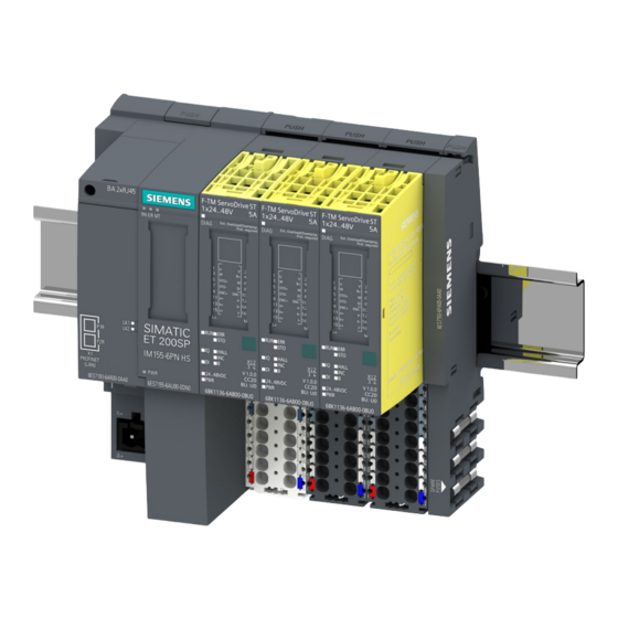
Page 18: Properties
Product overview 3.2 Properties Properties Article number 6BK1136-6AB00-0BU0 View of the module ① ⑧ Module type and designation Function class ② ⑨ LED for diagnostics Color coding of module type ③ ⑩ 2D matrix code Color code for selection of the color-coded labels ④... - Page 19 F-TM ServoDrive. You can find an overview of the BaseUnits that you can use with the technology module in the manual SIMATIC ET 200SP BaseUnits (https://support.industry.siemens.com/cs/ww/en/view/109751716). For more information on accessories, refer to the system manual SIMATIC ET200SP distributed I/O system (https://support.industry.siemens.com/cs/ww/en/view/58649293). F-TM ServoDrive Equipment Manual, 02/2020, A5E47579503-AA...
-
Page 20: Supported Functions
Product overview 3.3 Supported functions Supported functions System functions F-TM ServoDrive supports the following PROFINET IO functions: ● Firmware update via PROFINET IO F-TM ServoDrive supports the function: ● Identification data I&M 0 to 3 PROFIdrive communication types The F-TM Servo Drive supports the following types of communication: ●... -
Page 21: Wiring
Wiring Pin assignment Specific application Observe the safety and accident prevention regulations applicable for specific applications, e.g. "Safety of Machinery EN ISO 13849-1". During wiring and maintenance work, the F-TM ServoDrive must be disconnected from the power supply. EMERGENCY OFF equipment EMERGENCY OFF devices according to IEC 60204 (corresponds to DIN VDE 0113) must remain in effect in all operating modes of the plant or system. -
Page 22: Block Diagram
Protection from external electrical effects You can find information on interference-proof design in the function manual Designing interference-free controllers (https://support.industry.siemens.com/cs/ww/en/view/59193566). Overload The F-TM ServoDrive has overload capability. The 2-fold overload of the nominal current is cyclically permissible for a duration of 3 s and a subsequent recovery time of 17 s. During operation with cyclic overload, the rated power may not be exceeded as a time average (root-mean-square). - Page 23 Wiring 4.2 Block diagram Schematic circuit diagram ① Backplane bus Phase U ② Backplane bus interface module of the technol- Phase V ogy controller ③ Galvanic isolation Phase W ④ Technology controller Connection of braking resistor ⑤ Safe Torque Off circuitry STO+ STO+ input (24 V) ⑥...
- Page 24 Wiring 4.2 Block diagram Cable lengths and cable types If you do not use an "all-in-one" plug-in cable, the following cable lengths and cable types are permitted for the interfaces: Table 4- 1 Wiring rules for the interfaces Connector Function Maximum cable Cable type Cable cross-section...
-
Page 25: Wiring Of Multiple F-Tm Servodrive
Wiring 4.3 Wiring of multiple F-TM ServoDrive Wiring of multiple F-TM ServoDrive In a potential group You can connect multiple F-TM ServoDrive to form a potential group (drive line-up). The following figure shows you the F-TM ServoDrive with different motors. Wiring of multiple F-TM ServoDrive to form a drive line-up ①... -
Page 26: Connecting The Motor
Wiring 4.4 Connecting the motor Connecting the motor Overview F-TM ServoDrive supports permanent magnet synchronous motors (PMSM) with suitable encoders. Wiring the motor phases The following figure shows the connection of the motor phases to the BaseUnit: ① ② PMSM Braking resistor ③... -
Page 27: Connecting An Encoder
Wiring 4.5 Connecting an encoder Connecting an encoder 4.5.1 Connecting IQ-Encoders Motors from the SIMATIC MICRO-DRIVE Product Partner Program have an IQ encoder. The following figure shows the connection of IQ encoders to the BaseUnit. Figure 4-4 IQ encoder connection with differential signals Pin assignment of IQ encoder Designation Function... -
Page 28: Connecting Safe Torque Off (Hardware Sto)
Wiring 4.5 Connecting an encoder 4.5.2 Connecting safe torque off (Hardware STO) Safe Torque Off (STO) The safety function Hardware STO is activated via an exclusive safe input (STO+ and STO-). The F-TM ServoDrive safely switches off the control of the motor. As long as Hardware STO is active, the motor does not generate any torque. - Page 29 Wiring 4.5 Connecting an encoder Wiring the Hardware STO STO+ Safe torque off STO- Supply of STO Figure 4-5 Connection of Hardware STO Note The supply voltage for the STO inputs must be different from that of the power supply. Table 4- 2 Pin assignment Designation...
-
Page 30: Connecting The 24 V Digital Input
Wiring 4.5 Connecting an encoder 4.5.3 Connecting the 24 V digital input Connecting a 24 V digital input 24 V digital input Ground Figure 4-6 24 V digital input connection Table 4- 3 Pin assignment Designation Function Ground, internally connected to ground of 24 - 48 V power supply 24 V digital input F-TM ServoDrive... -
Page 31: Connecting An External Braking Resistor
Wiring a non-Siemens external braking resistor WARNING Damage to braking resistor If you use a non-Siemens external braking resistor, connect an overtemperature detection device to a digital input (e.g. a bimetallic switch that opens when the temperature is too high). - Page 32 Wiring 4.6 Connecting an external braking resistor Wiring an external braking resistor The figure below shows the connection of an external braking resistor as an example: Positive terminal of braking resistor Negative terminal of braking resistor Figure 4-7 Connection of external braking resistor Pin assignment Table 4- 5 Pin assignment: Wiring an external braking resistor...
-
Page 33: Safety Functions Integrated In The Drive
Safety functions integrated in the drive Basic safety information 5.1.1 General safety information WARNING Danger to life if the safety instructions and residual risks are not taken into consideration The non-observance of the safety instructions and residual risks stated in the associated F- TM ServoDrive documentation can result in accidents causing severe injuries or death. -
Page 34: Warranty And Liability For Application Examples
Safety functions integrated in the drive 5.1 Basic safety information 5.1.2 Warranty and liability for application examples Application examples are non-binding and do not claim to be complete regarding configuration and equipment as well as all eventualities. Application examples do not represent customer-specific solutions. -
Page 35: Safety Integrated Functions
Safety functions integrated in the drive 5.1 Basic safety information WARNING Danger to life as a result of undesirable motor motion when the system powers up and the drives are activated after hardware and/or software is changed or replaced After hardware and/or software components have been modified or replaced, or after drive parameters are changed or parameter backups are loaded, it is only permissible for the system to run up and the drives to be activated with the protective devices closed. - Page 36 Safety functions integrated in the drive 5.1 Basic safety information Examples of safety devices and 3 F-TM ServoDrive Note The supply voltage for the STO inputs must be different from that of the power supply. The following figure shows various safety devices connected to 3 F-TM ServoDrive. Figure 5-1 Safety devices and 3 F-TM ServoDrive Note...
-
Page 37: Safe Torque Off (Sto)
Safety functions integrated in the drive 5.1 Basic safety information Operating voltage range Operate input STO+ as intended with 19.2 to 28.8 V DC for the active enable or lower 5 V DC for the disable. Connect the input STO- for enabling or disabling the connection to ground. 5.1.4.1 Safe Torque Off (STO) Safe Torque Off (STO) is a safety function that directly stops torque- or force-producing... - Page 38 Safety functions integrated in the drive 5.1 Basic safety information Selection The STO safety function is always enabled and cannot be disabled via parameter assignment. You can select the STO function via the fail-safe digital input at STO+ and STO- terminals. The selection of the STO function is enabled directly as a response to safety messages (e.g.
-
Page 39: Overview Of The Safety Integrated Functions
Safety functions integrated in the drive 5.1 Basic safety information Hardware STO The F-TM ServoDrive internally monitors the fail-safe digital input at STO+ and STO- terminals for discrepancies. Discrepancy monitoring Due to the design of the Hardware STO circuit, a discrepancy cannot occur at STO+ and STO- terminals. -
Page 40: Supported Safety Functions
Safety functions integrated in the drive 5.1 Basic safety information 5.1.6 Supported safety functions The supported safety functions are included in the standard scope of the F-TM ServoDrive and can be used without an additional license. Stop functions The stop functions do not pose any special requirements on the utilized encoder and do not need actual value acquisition. -
Page 41: Safety Concept
Safety functions integrated in the drive 5.2 Acceptance of the safety functions 5.1.8 Safety concept The safety concept of the drive controller is based on a 2-channel system structure. Each channel has the possibility of bringing about the safe state, and the two channels monitor each other through a corresponding cross-comparison and cyclic diagnostics. -
Page 42: General Information On Acceptance
Safety functions integrated in the drive 5.2 Acceptance of the safety functions 5.2.1 General information on acceptance Why is acceptance required? The EU machinery directive and ISO 13849-1 stipulate: ● You must test safety-relevant functions and machine parts after commissioning. See "Acceptance test"... - Page 43 Safety functions integrated in the drive 5.2 Acceptance of the safety functions Requirements for the acceptance test ● The machine is correctly wired. ● All safety equipment (e.g. protective door monitoring devices, light barriers, emergency limit switches) are connected and ready for operation. ●...
- Page 44 Safety functions integrated in the drive 5.2 Acceptance of the safety functions Authorized persons Persons authorized by the machine manufacturer who, on account of their technical training and knowledge of the safety-relevant functions, can carry out the acceptance in an appropriate manner are entitled to perform the acceptance.
-
Page 45: Content Of An Acceptance Test
Safety functions integrated in the drive 5.2 Acceptance of the safety functions 5.2.2 Content of an acceptance test Documentation Documentation of the machine including safety functions ● Machine description (with overview image) ● Information on controller (if available) ● Function table: –... - Page 46 Safety functions integrated in the drive 5.2 Acceptance of the safety functions End customer Overview image of the machine Drive data In the following table, enter information on the drive components used and add additional components as required. Table 5- 3 Hardware components Component Designation...
-
Page 47: Acceptance Test For Safe Torque Off (Sto)
Safety functions integrated in the drive 5.2 Acceptance of the safety functions Utilized Safety Integrated functions In the following table, describe the use of the Safety Integrated drive functions in relation to your plant or machine. Table 5- 4 Utilized SI functions of the drive SI function Status/Description Safe Torque Off (STO) -
Page 48: Report Completion
Safety functions integrated in the drive 5.3 System features 5.2.5 Report completion SI change tracking (Safety logbook) Ensure that changes to the safety function (wiring) can be traced. Countersignatures Commissioning engineer Professional execution of the above-stated tests and checks is confirmed. Table 5- 6 Report completion - Countersignature of commissioning engineer Date... -
Page 49: Certifications
In addition, the safety functions of the drive are generally certified by independent institutes. A list of the components that are currently already certified in each case is available on request from your Siemens branch. 5.3.3 Failure probability of the safety functions The probability of failure of safety functions must be specified in the form of a PFH value (Probability of Failure per Hour) according to DIN EN 61800-5-2 and ISO 13849-1. -
Page 50: Response Times
Safety functions integrated in the drive 5.4 Safety Integrated 5.3.4 Response times The response time is the time between the detection of an input signal and the change of a linked output signal. Below you will find information on the response times of the F- TM ServoDrive drive system. -
Page 51: Emergency Off And Emergency Stop
Safety functions integrated in the drive 5.5 EMERGENCY OFF and EMERGENCY STOP EMERGENCY OFF and EMERGENCY STOP Difference between EMERGENCY OFF and EMERGENCY STOP EMERGENCY OFF and EMERGENCY STOP are commands that mitigate different risks in the machine or plant. EMERGENCY OFF EMERGENCY STOP Risk of electric shock... -
Page 52: Configuring
Configuring Configuration and parameter assignment STEP 7 (TIA Portal) is available for configuring a ET 200SP F-TM ServoDrive. You perform the following tasks with STEP 7 (TIA Portal), for example: ● You configure the F-TM ServoDrive (insertion into the project and setting the input addresses). -
Page 53: Communication Telegrams
Configuring 6.1 Communication telegrams Configuring the F-TM ServoDrive (minimal configuration) To configure a F-TM ServoDrive, follow these steps: 1. Create a new project. 2. Add a CPU S7-1200 or S7-1500 as a new device. 3. Add a PROFINET interface module to the project under "Devices & networks" from the ET200SP system, e.g. - Page 54 Configuring 6.1 Communication telegrams Selecting a telegram in STEP 7 To select the telegram for the F-TM ServoDrive in STEP 7, proceed as follows: 1. Select the F-TM ServoDrive in the device view. 2. Navigate to the properties of the module under the tab "General" > "F-TM ServoDrive ST" >...
-
Page 55: Commissioning The
Commissioning the The engineering of the F-TM ServoDrive ST drive controller is integrated in STEP 7 (TIA Portal). You install it with the Hardware Support Package HSP0311. The graphic user interface supports you in the configuration, parameter assignment and commissioning of the drive functions of the F-TM ServoDrive. -
Page 56: Basics
Commissioning the 7.1 Basics Basics 7.1.1 Engineering You perform configuration as well as diagnostics of a F-TM ServoDrive ST with a PG/PC or notebook (commissioning device) using the TIA Portal (Hardware Support Package HSP0311 needed). The settings can be found in STEP 7 in the device navigation under "Ungrouped devices" > "<Name of the interface module>"... -
Page 57: Drive Parameters
Commissioning the 7.1 Basics "Parameters" area Contents in the "Parameters" area of the F-TM ServoDrive TM engineering. ● Drive: Drive data record, general settings, motor, gearbox, thermal model, brake module ● Setpoint channel: Reference values, application limits, speed-ramp sensor ● Open-loop/closed-loop control: Control type, controller settings, speed controller, current controller ●... - Page 58 Commissioning the 7.1 Basics Changing a parameter You can directly change the values of the writable adjustable parameters (p-parameters) in STEP 7. You have the following options for this: ● You overwrite the current parameter value with the new value. ●...
-
Page 59: Calling Help Information
Commissioning the 7.1 Basics Conditions ● When you load parameters into the device, a rotating drive automatically stops. ● After the parameters are loaded, the drive does not restart automatically. You need to activate the drive via a new drive command. ●... -
Page 60: Requirements For The Commissioning
Commissioning the 7.2 Requirements for the commissioning Requirements for the commissioning Requirements ● The F-TM ServoDrive was installed according to the information in the following sections: – Wiring (Page 20) – Configuring (Page 51) ● The motor is installed in the drive train to be operated in accordance with the plant/device construction planning. - Page 61 Commissioning the 7.2 Requirements for the commissioning Module installation and wiring ● Is the F-TM ServoDrive plugged in / installed and firmly connected or screwed according to the assembly plan and configuration with STEP 7? ● Are all connectors wired according to the circuit diagram? ●...
-
Page 62: Commissioning Procedure For The Et 200Sp F-Tm Servodrive
Commissioning the 7.3 Commissioning procedure for the ET 200SP F-TM ServoDrive Commissioning procedure for the ET 200SP F-TM ServoDrive Procedure for commissioning with STEP 7 Commissioning is performed according to the steps listed below. The individual commissioning steps are optional and are to be performed as required. We recommend the following procedure for the first commissioning of a F-TM ServoDrive . -
Page 63: Drive Data Sets
(Harting, KnorrTec) of proven product partners of Siemens. This allows you to optimally combine suitable products from proven product partners for your individual application. You can find more information about the Siemens Product Partner Program in the Internet (https://new.siemens.com/global/en/products/drives/sinamics/servo-drive-system-simatic- micro-drive.html). - Page 64 Commissioning the 7.4 Drive data sets Thermal model The motor can be protected from thermal overload. Take section Messages/monitoring (Page 75) into consideration for this. You define the thermal properties of the motor in the "Parameters" > "Drive" > "Thermal model"...
-
Page 65: Using The Drive Data Set
Using the drive data set To configure a drive, you have the following options: ● Download preconfigured drive data sets as a file for selected motors from Siemens Industry Online Support. ● Create a user-defined drive data record and configure your motor manually. -
Page 66: Using Preconfigured Drive Data Sets
Using preconfigured drive data sets You have the option of using preconfigured drive data sets for configuring your motor. You can obtain preconfigured drive data sets for selected motors from Siemens Industry Online Support or product partners. Installing the drive data record Pre-configured drive data sets are provided as a file (tms *.mpk) and must be installed in... -
Page 67: Using A User-Defined Drive Data Set
Observe the information and notes in the help or in the tooltips of the individual parameters. You can also find detailed information and descriptions for the drive parameters in the Product Information (https://support.industry.siemens.com/cs/ww/en/view/109773204). You have selected user-defined editing of the drive and adapted the settings. F-TM ServoDrive... -
Page 68: Setpoint Channel
Commissioning the 7.5 Setpoint channel Setpoint channel Overview Setpoints from the respective setpoint source are prepared for the motor control in the setpoint channel of the drive. You specify the setpoints via the drive telegrams to PROFIdrive. You can find the settings for the setpoint channel in the context of the drive under "Parameters"... -
Page 69: Reference Values
Commissioning the 7.5 Setpoint channel 7.5.1 Reference values The physical variable speed is transmitted in the drive telegrams as a reference values. ● Speeds are normalized to the reference speed (p2000) in the drive telegram. Here, p2000 is decisive as the reference value (telegram content = 4000 hex or 4000 0000 hex for double words if the input variable has the value p2000). - Page 70 Commissioning the 7.5 Setpoint channel Speed limiting If you need a direction-dependent speed limiting, you can define speed limits for each direction. Torque limiting You can specify the torque limiting as an absolute value. The limiting acts both when motoring as well as generating. WARNING Danger to life due to uncontrolled movement of the drive as a result of incorrect parameter assignment...
-
Page 71: Ramp Generator
Commissioning the 7.5 Setpoint channel 7.5.3 Ramp generator The F-TM ServoDrive uses the speed ramp generator type "Basic ramp function generator" p1115[0]. Speed ramp generator The speed ramp generator is used to limit the acceleration at sudden setpoint changes and helps to prevent drive train shock loads. -
Page 72: Controller Settings
Commissioning the 7.6 Controller settings Controller settings 7.6.1 Open-loop/closed-loop control Under "Parameters" > "Open-loop/closed-loop control", you specify the general controller settings and the settings for speed and current controllers. General controller settings You can optimally tune speed and current controllers if you specify the properties of the load in the machine due to mechanical systems and the electrical properties of the motor connection. - Page 73 Commissioning the 7.6 Controller settings Speed controller and current controller You can either set the speed and current controller manually or have the controller settings calculated by STEP 7. Having controller settings calculated To have the controller settings of STEP 7 calculated, proceed as follows: 1.
-
Page 74: Filters
Commissioning the 7.6 Controller settings Note If you manually set the controller parameters to inappropriate values, the drive system can be damaged. Make changes to the controller settings in small steps. Keep checking the behavior of the drive system until you have found a satisfactory setting. 7.6.2 Filters Speed setpoint filter... - Page 75 Commissioning the 7.6 Controller settings OFF2 (Coast down) You activate OFF2 and the drive coasts down by resetting bit 1 in STW1 (NoCoastStop). Note NOTE on rapid stop (OFF3) You trigger a quick stop (OFF3) by resetting bit 2 in STW1 (NoQuickStop). The rapid stop takes into account the ramp-down time configured in the HSP ("Parameter"...
-
Page 76: Messages/Monitoring
Commissioning the 7.7 Messages/monitoring Messages/monitoring Thermal monitoring The purpose of thermal monitoring is to detect critical states. Parameterizable warning thresholds are available that allow further operation of the drive (e.g. with reduced power) and prevent an immediate shutdown. However, the parameter assignment options are only interventions below the shutdown thresholds. -
Page 77: Motor
Commissioning the 7.7 Messages/monitoring 7.7.1 Motor Thermal motor monitoring The thermal motor monitoring is performed using a configurable I²t temperature model. WARNING Thermal motor utilization cannot be immediately determined after initialization The thermal model is reinitialized after changing the drive data record and when switching on the device. -
Page 78: Power End Stage
Commissioning the 7.7 Messages/monitoring 7.7.3 Power end stage Thermal monitoring of power end stage The power end stage is monitored with a temperature sensor. You can specify the warning threshold (p0291[1]) relative to the shutdown threshold "System maximum temperature power end stage". Procedure 1. - Page 79 Commissioning the 7.7 Messages/monitoring Procedure 1. Open the "Intermediate circuit voltage" area in the context of the drive under "Parameters" > "Messages/monitoring". 2. Configure the minimum value (p0390) and the maximum value (p0391). WARNING Operation above the voltage setting range Under the given application conditions, ensure that the motor is not operated above the voltage setting range by selecting the appropriate motor and gear unit.
-
Page 80: Programming
Programming F-TM ServoDrive does not have its own control panel. A user program is required to control the motion sequences. You have the following options for controlling the motion sequences in the user program: ● Control via the process image (Page 79) ●... - Page 81 Programming 8.1 Controlling F-TM ServoDrive via the process image Bool Data type Offset Bit06_SwitchingOnInhibited Bool Bit07_AlarmPresent Bool Speed setpoint NACT_A Word Telegram extension word (only with telegram Structure extension) Reserved Byte Telegram extension STO_Status Bool Telegram extension DI_Status Bool Outputs Element Data type Offset...
- Page 82 Programming 8.1 Controlling F-TM ServoDrive via the process image Standard telegram 2 Structure I/O addresses Inputs Bool Data type Offset Status word 1 Struct Bit08_NoSpeedDeviation Bool Bit09_ControlRequested Bool Bit10_SpeedComparisonValueReachedExeed Bool Bit11_Reserved Bool Bit12_Reserved Bool Bit13_Reserved Bool Bit14_Reserved Bool Bit15_Reserved Bool Bit00_ReadyToSwitchON Bool Bit01_ReadyToOperate...
- Page 83 Programming 8.1 Controlling F-TM ServoDrive via the process image Outputs Element Data type Offset Control word 1 Struct Bit08_Reserved Bool Bit09_Reserved Bool Bit10_ControlByPlc Bool Bit11_Reserved Bool Bit12_Reserved Bool Bit13_Reserved Bool Bit14_Reserved Bool Bit15_Reserved Bool Bit00_On Bool Bit01_NoCoastStop Bool Bit02_NoQuickStop Bool Bit03_EnableOperation Bool Bit04_EnableRampGenerator...
- Page 84 Programming 8.1 Controlling F-TM ServoDrive via the process image Standard telegram 3 Structure I/O addresses Inputs Bool Data type Offset Status word 1 Struct Bit08_NoSpeedDeviation Bool Bit09_ControlRequested Bool Bit10_SpeedComparisonValueReachedExeed Bool Bit11_Reserved Bool Bit12_Reserved Bool Bit13_Reserved Bool Bit14_Reserved Bool Bit15_Reserved Bool Bit00_ReadyToSwitchON Bool Bit01_ReadyToOperate...
- Page 85 Programming 8.1 Controlling F-TM ServoDrive via the process image Bool Data type Offset Bit11_EncoderFaultAcknowlegdeActive Bool Bit12_HomePositionExecuted Bool Bit13_AbsoluteValueCyclicallyExecuted Bool Bit14_ReservedParkingSensorExecuted Bool Bit15_ParkingSensorExecuted Bool Bit00_Function1Active Bool Bit01_Function2Active Bool Bit02_Function3Active Bool Bit03_Function4Active Bool Bit04_Value1Available Bool Bit05_Value2Available Bool Bit06_Value3Available Bool Bit07_Value4Available Bool Actual encoder position value 1 DWord 10.0 Actual encoder position value 2...
- Page 86 Programming 8.1 Controlling F-TM ServoDrive via the process image Element Data type Offset Bit08_Reserved Bool Bit09_Reserved Bool Bit10_Reserved Bool Bit11_Reserved Bool Bit12_Reserved Bool Bit13_Reserved Bool Bit14_Reserved Bool Bit15_Reserved Bool Bit00_Reserved Bool Bit01_Reserved Bool Bit02_Reserved Bool Bit03_Reserved Bool Bit04_Reserved Bool Bit05_Reserved Bool Bit06_Reserved Bool...
-
Page 87: Controlling A F-Tm Servodrive Via The Sina_Speed Instruction
For controlling the F-TM ServoDrive, you can also use the SINA-SPEED instruction from the "DriveLib" block library. The "DriveLib" block library can be downloaded from the Internet (https://support.industry.siemens.com/cs/ww/en/view/109475044). Controlling F-TM ServoDrive with a technology object Control with a technology object You can also use a technology object, e.g. -
Page 88: Maintenance
Firmware update Firmware update A firmware update is possible via PROFINET. See SIMATIC ET200SP distributed I/O system (https://support.industry.siemens.com/cs/ww/en/view/58649293). Stop responses Overview of the stop responses Faults with safety functions and violation of limits can trigger the following stop responses: ● "Hardware STO"... -
Page 89: Interrupts, Error Messages And Diagnostics And System Alarms
Interrupts, error messages and diagnostics and system alarms 10.1 Status and error displays LED display The figure below shows the LEDs on the F-TM ServoDrive. ① ⑦ DIAG (red/green) PWR (green) ② ⑧ ERR (red) 24..48V (green) ③ ⑨ STO (yellow) DI (green) Display not safety-related ④... - Page 90 Interrupts, error messages and diagnostics and system alarms 10.1 Status and error displays Meaning of the LED displays The following tables contain the meanings of the status and error displays. DIAG LED Table 10- 1 DIAG status and error display DIAG LED Meaning Backplane bus supply of the ET 200SP not OK...
- Page 91 Interrupts, error messages and diagnostics and system alarms 10.1 Status and error displays DI LED Table 10- 4 DI status and error display DI LED Meaning Input is faulty/inactive Input is error-free/active B LED Table 10- 5 B status and error display B LED Meaning Braking resistor/brake chopper configured as "active"...
- Page 92 Interrupts, error messages and diagnostics and system alarms 10.1 Status and error displays INC LED Table 10- 9 Status and error display INC (encoder) INC LED Meaning Incremental speed encoder was assigned parameters/activated 24..48V LED Table 10- 10 24..48V status and error display 24..48V LED Meaning DC link voltage outside the configured limits...
-
Page 93: Diagnostics
Interrupts, error messages and diagnostics and system alarms 10.2 Diagnostics 10.2 Diagnostics 10.2.1 Diagnostics overview of the F-TM ServoDrive Diagnostic view of the CPU and its associated I/O If you go online to the CPU and establish an online connection via the CPU to the F-TM ServoDrive, this occurs within the project context. -
Page 94: Active Messages
Interrupts, error messages and diagnostics and system alarms 10.2 Diagnostics 10.2.2 Active messages Pending faults and alarms "Active messages" shows the currently pending faults and alarms in the F-TM ServoDrive. Faults must be acknowledged after the cause has been corrected. Procedure To display the active messages, follow these steps: 1. -
Page 95: Drive Diagnostics
Interrupts, error messages and diagnostics and system alarms 10.2 Diagnostics Alarms Column Description Alarm number Number of the warning Description Description of the warning The F-TM ServoDrive supports the following warnings. Alarm number Description 2000 Voltage in the intermediate circuit shortly before shutdown 2001 STO shutdown active 2002... - Page 96 Interrupts, error messages and diagnostics and system alarms 10.2 Diagnostics Drive diagnostics: Status bits "Online & diagnostics" > "Diagnostics" > "Drive diagnostics" > "Status bits" Table 10- 12 Drive diagnostics - status bits Number Parameter Display/unit Status word r0899 Status bits Ready for switching on •...
- Page 97 All displayed parameters have a tooltip that provides you with information and descriptions relating to the parameter as well as access to the online help. You can find additional information on the parameters in the Product Information (https://support.industry.siemens.com/cs/ww/en/view/109773204). F-TM ServoDrive Equipment Manual, 02/2020, A5E47579503-AA...
-
Page 98: Technical Specifications
Technical specifications 11.1 Technical specifications of the ET 200SP F-TM ServoDrive Technical specifications of the F-TM ServoDrive Article number 6BK1136-6AB00-0BU0 General information Product type designation F-TM ServoDrive 1x24 ... 48 V 5 A ST HW functional status V1.0 Firmware version V1.0 FW update possible •... - Page 99 Technical specifications 11.1 Technical specifications of the ET 200SP F-TM ServoDrive Article number 6BK1136-6AB00-0BU0 Output voltage Rated value, min. 24 V Rated value, max. 48 V Output current Current output (rated value) Output current, max. 10 A Output frequency 420 Hz Encoder supply Number of outputs 5 V encoder supply...
- Page 100 Technical specifications 11.1 Technical specifications of the ET 200SP F-TM ServoDrive Article number 6BK1136-6AB00-0BU0 Potential separation Potential separation channels between the channels and backplane bus • Isolation Isolation tested with 707 V DC/1 min, type test (between backplane bus and functional ground) Overvoltage category Degree of pollution 2 according to EN 61800-5-1...
- Page 101 Climatic and mechanical environmental conditions You can find the climatic and mechanical ambient conditions here SIMATIC ET200SP distributed I/O system (https://support.industry.siemens.com/cs/ww/en/view/58649293). If there are discrepancies between the statements in this document and the system manual, the statements in the this document take priority.
-
Page 102: Derating Of The Et 200Sp F-Tm Servodrive
Technical specifications 11.2 Derating of the ET 200SP F-TM ServoDrive 11.2 Derating of the ET 200SP F-TM ServoDrive Maximum permitted output current as a function of installation altitude and ambient temperature You must take into account the dependency on the ambient temperature and installation altitude. -
Page 103: Response Times
Response times Response times Introduction Below you can find the response time of the F-TM ServoDrive in STEP7. The response times of the F-TM ServoDrive are included in the calculation of the response time of the F-system. The drive system is the component that provides the safety functions. Definition of response time The response time is the time between the detection of an input signal and the change of a linked output signal. - Page 104 Response times A.1 Response times Times required for the calculation Function Maximum response time STOP_STO via terminal 20 ms STOP_STO: With a STOP_STO, the drive safely switches off the torque of the connected motor immediately. F-TM ServoDrive Equipment Manual, 02/2020, A5E47579503-AA...
-
Page 105: Data Sets
Data sets You can find an overview of the data sets for the F-TM ServoDrive and the structure of the data sets in the product information (https://support.industry.siemens.com/cs/ww/en/view/109773204). F-TM ServoDrive Equipment Manual, 02/2020, A5E47579503-AA... -
Page 106: Index
Index Preconfigured, 65 User-defined, 66 Drive diagnostics Encoders, 96 Acceptance, 41 Inputs, 96 Report, 41 Operating values, 95 Requirements, 41 Status bits, 95 Acceptance test Temperatures, 96 Authorized person, 43 Requirements, 42 Actual encoder position value, 52 Adjustable parameters, 57 Alarms, 93 Electronic rating plate, 26 Ambient temperature, 101... - Page 107 Index Machine manufacturer, 43 Writable parameters, (see adjustable parameters) OFF1, 69 Zero speed detection, 69 OFF1 (Switch off), 73 OFF2 (Coast down), 74 OFF3, 69 Overload, 21 PFH value, 48 Probability of failure, 48 PROFIdrive, 19 Isochronous, 19 Protection from external electrical effects, 21 Ramp generator Properties, 70 Reference values, 68...