Siemens SIMATIC ET 200SP Manual
Analog output module aq 4xu/i st 6es7135-6hd00-0ba1
Hide thumbs
Also See for SIMATIC ET 200SP:
- System manual (320 pages) ,
- Manual (270 pages) ,
- Operating instructions manual (166 pages)
Table of Contents
Advertisement
Advertisement
Table of Contents

Related Manuals for Siemens SIMATIC ET 200SP


Summary of Contents for Siemens SIMATIC ET 200SP
- Page 2 ___________________ Analog Output Module AQ 4xU/I ST Preface (6ES7135-6HD00-0BA1) ___________________ Documentation guide ___________________ Product overview SIMATIC ___________________ Wiring up ET 200SP Analog Output Module AQ 4xU/I ST ___________________ Parameters/address space (6ES7135-6HD00-0BA1) ___________________ Interrupts/diagnostics alarms Manual ___________________ Technical specifications ___________________ Parameter data record ___________________ Representation of analog values...
- Page 3 Note the following: WARNING Siemens products may only be used for the applications described in the catalog and in the relevant technical documentation. If products and components from other manufacturers are used, these must be recommended or approved by Siemens. Proper transport, storage, installation, assembly, commissioning, operation and maintenance are required to ensure that the products operate safely and without any problems.
-
Page 4: Preface
Purpose of the documentation This manual supplements the system manual ET 200SP distributed I/O system (http://support.automation.siemens.com/WW/view/en/58649293). Functions that generally relate to the system are described in this manual. The information provided in this manual and in the system/function manuals supports you in commissioning the system. - Page 5 Siemens recommends strongly that you regularly check for product updates. For the secure operation of Siemens products and solutions, it is necessary to take suitable preventive action (e.g. cell protection concept) and integrate each component into a holistic, state-of-the-art industrial security concept.
-
Page 6: Table Of Contents
Table of contents Preface ..............................4 Documentation guide ..........................7 Product overview ..........................11 Properties ..........................11 Wiring up .............................. 14 Terminal assignment ......................14 Schematic circuit diagram ...................... 15 Parameters/address space ........................16 Output ranges ........................16 Parameters ..........................17 Explanation of the parameters .................... -
Page 7: Documentation Guide
Documentation guide The documentation for the SIMATIC ET 200SP distributed I/O system is arranged into three areas. This arrangement enables you to access the specific content you require. Basic information The system manual describes in detail the configuration, installation, wiring and commissioning of the SIMATIC ET 200SP. - Page 8 You can download the product information free of charge from the Internet (https://support.industry.siemens.com/cs/us/en/view/73021864). Manual Collection ET 200SP The Manual Collection contains the complete documentation on the SIMATIC ET 200SP distributed I/O system gathered together in one file. You can find the Manual Collection on the Internet (http://support.automation.siemens.com/WW/view/en/84133942).
- Page 9 ● Manuals, characteristics, operating manuals, certificates ● Product master data You can find "mySupport" - CAx Data in the Internet (http://support.industry.siemens.com/my/ww/en/CAxOnline). Application examples The application examples support you with various tools and examples for solving your automation tasks. Solutions are shown in interplay with multiple components in the system - separated from the focus in individual products.
- Page 10 You can find the SIMATIC Automation Tool on the Internet (https://support.industry.siemens.com/cs/ww/en/view/98161300). PRONETA With SIEMENS PRONETA (PROFINET network analysis), you analyze the plant network during commissioning. PRONETA features two core functions: ● The topology overview independently scans PROFINET and all connected components.
-
Page 11: Product Overview
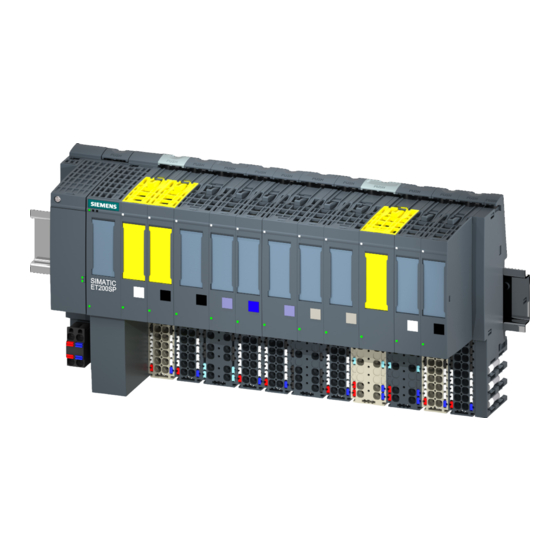
Product overview Properties Article number 6ES7135-6HD00-0BA1 View of the module Image 2-1 View of the module AQ 4×U/I ST Analog Output Module AQ 4xU/I ST (6ES7135-6HD00-0BA1) Manual, 03/2016, A5E03573365-AD... - Page 12 Product overview 2.1 Properties Properties The module has the following technical properties: ● Analog output module with 4 outputs – For current output and – voltage output ● Output range for current output: – ±20 mA, resolution 16 bits including sign –...
- Page 13 ● Color identification labels ● Reference identification label ● Shield connector See also You will find additional information on the accessories in the ET 200SP distributed I/O system (http://support.automation.siemens.com/WW/view/en/58649293) system manual. Analog Output Module AQ 4xU/I ST (6ES7135-6HD00-0BA1) Manual, 03/2016, A5E03573365-AD...
-
Page 14: Wiring Up
The first BaseUnit of a station must be a light-colored BaseUnit. Also keep this in mind during the configuration. You will find additional information on the BaseUnit types in the ET 200SP distributed I/O system (http://support.automation.siemens.com/WW/view/en/58649293) system manual. Analog Output Module AQ 4xU/I ST (6ES7135-6HD00-0BA1) Manual, 03/2016, A5E03573365-AD... -
Page 15: Schematic Circuit Diagram
Wiring up 3.2 Schematic circuit diagram Schematic circuit diagram Schematic circuit diagram Image 3-1 Schematic circuit diagram for AQ 4×U/I ST Analog Output Module AQ 4xU/I ST (6ES7135-6HD00-0BA1) Manual, 03/2016, A5E03573365-AD... -
Page 16: Parameters/Address Space
Parameters/address space Output ranges The analog output module AQ 4×U/I ST has the following measuring ranges: Table 4- 1 Output ranges Output type Output ranges Resolution Current ± 20 mA 16 bits including sign 0 to 20 mA 15 bits 4 to 20 mA 14 bits Voltage... -
Page 17: Parameters
Parameters/address space 4.2 Parameters Parameters Parameters of the AQ 4xU/I ST The effective range of the parameters depends on the type of configuration. The following configurations are possible: ● Central operation with an S7-1500 CPU ● Distributed operation on PROFINET IO in an ET 200SP system ●... - Page 18 Parameters/address space 4.2 Parameters Parameters Value range Default Configuration Effective range with configuration in RUN software, e.g. STEP 7 (TIA Portal) GSD file GSD file PROFINET IO PROFIBUS DP Substitute value For permissible substitute Channel Channel values for the various output ranges, see appen- dix Parameter data record (Page 30), Substitute val-...
-
Page 19: Explanation Of The Parameters
The substitute value is the value that the module outputs in case of a CPU STOP. Potential group Specifies that a BaseUnit with voltage supply feed-in is located in this slot (see system manual ET 200SP Distributed I/O System (http://support.automation.siemens.com/WW/view/en/58649293)). Analog Output Module AQ 4xU/I ST (6ES7135-6HD00-0BA1) Manual, 03/2016, A5E03573365-AD... -
Page 20: Address Space
Parameters/address space 4.4 Address space Address space Configuration options The following configurations are possible: ● Configuration 1: Without value status ● Configuration 2: With value status Evaluating the value status If you enable the value status for the analog module, an additional byte is occupied in the input address space. -
Page 21: Interrupts/Diagnostics Alarms
Interrupts/diagnostics alarms Status and error display LED display The figure below shows the LED displays of the AQ 4xU/I ST. ① DIAG (green/red) ② Channel status (green) ③ PWR (green) Image 5-1 LED display Analog Output Module AQ 4xU/I ST (6ES7135-6HD00-0BA1) Manual, 03/2016, A5E03573365-AD... - Page 22 Interrupts/diagnostics alarms 5.1 Status and error display Meaning of the LED displays The following tables show the meaning of the status and error displays. Measures for dealing with diagnostics alarms can be found in the section Diagnostics alarms (Page 24). DIAG LED Table 5- 1 DIAG LED fault/error display...
-
Page 23: Interrupts
Interrupts/diagnostics alarms 5.2 Interrupts Interrupts The analog output module AQ 4×U/I ST supports diagnostic interrupts. Diagnostics interrupt The module generates a diagnostics interrupt for the following events: ● Channel temporarily unavailable ● Short-circuit (voltage) ● Overtemperature ● Line break (current) ●... -
Page 24: Diagnostics Alarms
Interrupts/diagnostics alarms 5.3 Diagnostics alarms Diagnostics alarms A diagnostics alarm is output for each diagnostics event and the DIAG LED on the module flashes. The diagnostics alarms can, for example, be read from the diagnostics buffer of the CPU. You can evaluate the error codes with the user program. Table 5- 4 Diagnostics alarms, their meaning and how to deal with them Diagnostics alarm... -
Page 25: Technical Specifications
Technical specifications Technical specifications Technical specifications of AQ 4×U/I ST 6ES7135-6HD00-0BA1 Product type designation AQ 4xU/I ST General information Firmware version V1.1 Usable BaseUnits BU type A0, A1 Color code for module-specific color identification label CC00 Product function I&M data Engineering with STEP 7 TIA Portal can be configured/integrated as of version V11 SP2 / V13 STEP 7 can be configured/integrated as of version... - Page 26 Technical specifications 6.1 Technical specifications 6ES7135-6HD00-0BA1 Analog outputs Number of analog outputs Voltage output, short-circuit current, max. 45 mA Cycle time (all channels), min. 5 ms Output ranges, voltage 0 to 10 V Yes; 15 bits 1 to 5 V Yes;...
- Page 27 Technical specifications 6.1 Technical specifications 6ES7135-6HD00-0BA1 Basic error limit (operational limit at 25 °C) Voltage in relation to output range, (+/-) ±0.3 % Current in relation to output range, (+/-) ±0.3 % Interrupts/diagnostics/status information Substitute values can be applied Interrupts Diagnostics interrupt Diagnostics alarms Diagnostics...
- Page 28 Technical specifications 6.1 Technical specifications Derating trend for permitted load during power output and horizontal mounting position: Image 6-1 Derating trend current output (horizontal) Derating trend for permitted load during power output and vertical mounting position: Image 6-2 Derating trend current output (vertical) Analog Output Module AQ 4xU/I ST (6ES7135-6HD00-0BA1) Manual, 03/2016, A5E03573365-AD...
- Page 29 Technical specifications 6.1 Technical specifications Dimension drawing See manual ET 200SP BaseUnits (http://support.automation.siemens.com/WW/view/en/59753521) Analog Output Module AQ 4xU/I ST (6ES7135-6HD00-0BA1) Manual, 03/2016, A5E03573365-AD...
-
Page 30: Parameter Data Record
Parameter data record Dependencies when configuring with GSD file When configuring the module with a GSD file, remember that the settings of some parameters are dependent on each other. Configuring with a PROFINET GSD file The table lists the properties and their dependencies on the output type and output range for PROFINET. -
Page 31: Parameter Assignment And Structure Of The Parameter Data Record
Parameter data record A.2 Parameter assignment and structure of the parameter data record Parameter assignment and structure of the parameter data record Parameter assignment in the user program The module can be re-configured in RUN (for example, the voltage or current values of selected channels can be changed in RUN without having an effect on the other channels). - Page 32 Parameter data record A.2 Parameter assignment and structure of the parameter data record Header information The figure below shows the structure of the header information. Image A-2 Header information Parameters The figure below shows the structure of the parameters for channels 0 to 3. You enable a parameter by setting the corresponding bit to "1".
- Page 33 Parameter data record A.2 Parameter assignment and structure of the parameter data record Codes for output type The following table contains the codes for the output types of the analog output module. You enter this coding in byte x (see previous figure). Table A- 1 Codes for output type Output type...
-
Page 34: Representation Of Analog Values
Representation of analog values This appendix describes the analog values for all output ranges that you can use with the analog module AQ 4xU/I ST. Measured value resolution The digitized analog value is the same for all output values at the same nominal range. Analog values are output as fixed point numbers in two's complement. -
Page 35: Representation Of Output Ranges
Representation of analog values B.1 Representation of output ranges Representation of output ranges In the following tables, you can find the digitized representation of the bipolar and unipolar range output ranges. The resolution is 16 bits. Table B- 2 Bipolar output ranges Dec. -
Page 36: Representation Of Analog Values In The Voltage Output Ranges
Representation of analog values B.2 Representation of analog values in the voltage output ranges Representation of analog values in the voltage output ranges The tables below list the decimal and hexadecimal values (codes) of the possible voltage output ranges. Table B- 4 Voltage output ranges ±10 V and ±5 V Values Voltage output range... -
Page 37: Representation Of Analog Values In The Current Output Ranges
Representation of analog values B.3 Representation of analog values in the current output ranges Table B- 6 Voltage output range 1 V to 5 V Values Voltage output range Range Dec. Hex. 1 to 5 V 118.519 % 32767 7FFF 5.70 V Overflow* 32512... - Page 38 Representation of analog values B.3 Representation of analog values in the current output ranges Table B- 8 Current output range 0 to 20 mA Values Current output range Range Dec. Hex. 0 to 20 mA 118.5149 % 32767 7FFF 21 mA Overflow* 29031 7167...