Comelit 6721W Technical Manual
Vip mini hands-free monitor
Hide thumbs
Also See for 6721W:
- Technical manual (25 pages) ,
- Instruction manual (11 pages) ,
- Technical manual (8 pages)

Related Manuals for Comelit 6721W


Summary of Contents for Comelit 6721W
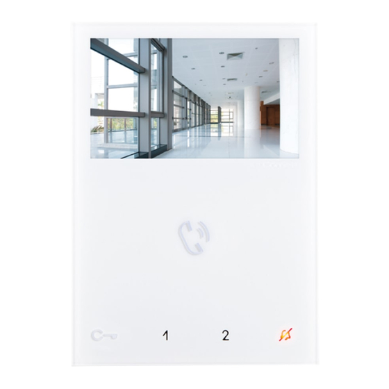
- Page 1 TECHNICAL MANUAL ViP Mini hands-free monitor art. 6721W Passion.Technology. Design.
-
Page 2: Table Of Contents
Table of contents Warning Monitor description ................. 3 Soft-touch key description ..............4 Indicator LED description................4 Technical specifications ..............5 Installation ..................7 Removing / Fitting the terminal ..............8 Connections ..................8 Monitor configuration ..............9 Standard configuration for soft-touch keys ..........9 Activation/deactivation automatic answer mode .........9 Configuration of Main and Secondary internal units - Dip 8 of S2 ..10 Power supply configuration and management - Dip 7 of S2 .....10... -
Page 3: Monitor Description
The Mini Vivavoce series is comprised of hands-free monitors that can be used in “Building Kit” (exclusively 2 wire), Simplebus Top and Kit Video systems. • Article 6721W is a colour monitor equipped as standard with 5 buttons (3 additional buttons can be added with the accessory Art. 6734W) •... -
Page 4: Soft-Touch Key Description
(idle): automatic answer activated continuous flashing: incoming call The monitor Art. 6721W is designed for use in colour systems, in the SB2 section downstream of Art. 4888C, or in systems without mixer, such as the system with 2-wire KIT or Art. 1210. -
Page 5: Technical Specifications
Technical specifications MAIN SPECIFICATIONS 6721W 6721W/BM Audio/video system Wall-mounted Desk base-mounted Hands-free function Induction loop function Type of display Display size (inches) 4,3" 16/9 4,3" 16/9 Display resolution (H x V) 480x272pixel 480x272pixel B/W or colour display Color Colors Product colour... - Page 6 TECHNICAL SPECIFICATIONS 6721W 6721W/BM Power supply voltage 22÷28Vdc 22÷28Vdc Absorption Maximum current absorption (mA) Microphone 6mm omni-direction 6mm omni-direction Loudspeaker 36mm 40Ohm 1W 36mm 40Ohm 1W IP Rating Operating temperature (°C) -5÷40 -5÷40 Relative humidity for operation 25 - 75 %...
-
Page 7: Installation
Installation 115 mm optional fixing... -
Page 8: Removing / Fitting The Terminal
Removing / Fitting the terminal Connections VIDEO ENTRY SYSTEM RISER 6721W 1214/2C FLOOR DOOR CALL VIDEO ENTRY SYSTEM RISER 20 m MAX - Use shielded cable for the connection and do not route the cables in the vicinity of heavy inductive loads or power supply cables (230V/400V). -
Page 9: Monitor Configuration
Monitor configuration Standard configuration for soft-touch keys DIP S2 Art. 6721W(/BM) + Art. 6734 DIP 1 DIP 2 DIP 3 DIP 4 INTb INTb INTb INTb INTb INTb NULL NULL NULL NULL NULL NULL PROG Standard configuration for DIP switches 1-2-3-4... -
Page 10: Configuration Of Main And Secondary Internal Units - Dip 8 Of S2
Configuration of Main and Secondary internal units - Dip 8 of S2 f To configure an internal unit as the main unit, set DIP8 of S2 to OFF. f To configure an internal unit as a secondary unit, set DIP8 of S2 to ON. DIP 8 DIP 8 (S2) -
Page 11: Advanced Monitor Configuration
Advanced monitor configuration Warning If the default settings (see “Standard configuration for soft-touch keys”) do not reflect requirements, the keys can be programmed differently by carrying out the steps below. At the end, set S2 DIP switches 1-2-3-4 to the combination 1111 (PROG setting in the configuration tables “Advanced monitor configuration”). -
Page 12: Programming Buttons For Intercom Call
Programming buttons for intercom call DIP S2 Art. 6721W(/BM) + Art. 6734 DIP S1 DIP 1 DIP 2 DIP 3 DIP 4 INTb INTb INTb ADDRESS INTb INTb INTb PROG Example 1 - all systems (INCLUDING KITS!) - General intercom... -
Page 13: Direct Programming Of Intercom Call
Direct programming of intercom call Allows direct programming of intercom call via the internal units. √ Requires 2 operators Step 1: enter programming mode Operator 1 and Operator 2 carry out the following procedures on 2 internal units: 1. Set S2 DIP switches 1-2 -3-4 to the combination 1111 2. -
Page 14: Programming Keys For Generic Or Coded Actuator
Programming keys for generic or coded actuator DIP S2 Art. 6721W(/BM) + Art. 6734 DIP S1 DIP 1 DIP 2 DIP 3 DIP 4 ADDRESS PROG Example: on a monitor with user code 5, P1 programming = generic actuator, P2 = coded actuator (code 125) Take note of the DIP-switch settings 1. -
Page 15: Programming Buttons For Other Functions
Programming buttons for other functions DIP S2 Art. 6721W(/BM) + Art. 6734 DIP 1 DIP 2 DIP 3 DIP 4 NULL NULL NULL NULL NULL NULL PROG Legend Lock- release Self-ignition Main switchboard call – not for use in systems with KIT Secondary switchboard call –... -
Page 16: Programming Range
Programming range Take note of the S2, S1 setting and restore it when programming is complete Carry out steps 1 to 4 S2 DIP Range minimum 1 2 3 4 5 6 address 0 0 0 0 1 0 set code, “addressing table”... -
Page 17: Programming Reset
Programming reset Factory settings: • Button functions for the S2 DIP switch 1-2-3-4 combination; • Intercom address absent; • Range function and min./max. addresses absent; DIP OFF • Ringtone reset. Take note of the S2, S1 setting and restore it when programming is complete S2 DIP DIP ON 1 2 3 4 5 6... - Page 18 C E R T I F I E D M A N A G E M E N T S Y S T E M S w w w . c o m e l i t g r o u p . c o m Via Don Arrigoni, 5 - 24020 Rovetta (BG) - Italy...