Comelit 6741W Technical Manual
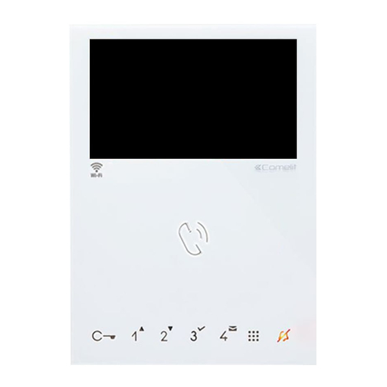
Mini hands-free door entry monitor
Hide thumbs
Also See for 6741W:
- Technical manual (36 pages) ,
- Operating manual (20 pages) ,
- User manual (10 pages)

Related Manuals for Comelit 6741W


Summary of Contents for Comelit 6741W
- Page 1 TECHNICAL MANUAL Mini hands-free door entry monitor Art. 6741W - Art. 6741W/BM Passion.Technology.Design.
-
Page 2: Table Of Contents
Programming range ................18 Changing monitor ringtones ..............18 Programming reset ................19 Compatible secondary monitors..........20 Art. 6741W (/BM) in systems powered by 4888C / 4888CU ..20 Installation rules ..................20 New coding from rev. 053 ..............20 Operating distances ................21 Art. 6741W (/BM) in systems powered by 1210 ......22 Operating distances ................22... -
Page 3: Description
Description Monitors 6741W and 6741W/BM are hands-free colour video internal units, for installation in 2-wire video entry phone systems and compatible only with power supply units 1209, 1210, 4888C and 4888CU. The monitor, used in conjunction with the COMELIT app, makes it possible to answer calls directly from your smartphone/ tablet, whether you are at home or away. -
Page 4: Technical Characteristics
White White Sensitive Touch technology Number of buttons as standard LED indication (n) Backlighting colour White White Wi-Fi Compatible with Comelit app HARDWARE CHARACTERISTICS Removable terminals ADJUSTMENTS Loudspeaker volume Brightness GENERAL DATA Product height (mm) Product width (mm) Product depth (mm) -
Page 5: Installation
Installation Before definitive installation of the monitors, make sure the device has good Wi-Fi signal reception; the distance between the router and monitors, and the construction materials used in the walls are factors that can affect signal quality. The Wi-Fi signal is not strong enough to guarantee correct operation. A Wi-Fi repeater must be installed between the router and monitor in order to boost the Wi-Fi signal received by the monitor. -
Page 6: Removing The Monitor
Removing the monitor Removing/Fitting the terminal... -
Page 7: Connections
Where multiple door-entry phones or monitor backplates have the same user code, connect the CFP button on one only; all the devices will ring simultaneously. Operation Once connected to the power supply, the LEDs for monitor 6741W (/BM) will flash: wait for them to turn off (approx. 40 seconds) before starting to use the device. Answering an incoming call Press the touch-sensitive audio activation button to answer the incoming call. -
Page 8: Touch Buttons
Touch buttons Description f Press the desired button once to activate the function associated with it. Wait for approx. 1 sec. before pressing the same button again; rapidly pressing the same button repeatedly will cancel the command which has just been sent. Audio activation Door opener control [programmable]... -
Page 9: Configuration
(see below) and in accordance with the type of system and its configuration: art. 4888C / 4888CU art. 1210 art. 1209 N.B. A single 6741W monitor can be installed for each user code; this will also be the only main monitor. 6741W 6741W 6741W/BM 6741W/BM... -
Page 10: Addressing Table
Addressing table “Addressing table” NOTES • In BUILDING mode we recommend choosing user codes with free lower values. • Code *240 is reserved for the porter switchboard. -
Page 11: Programmable Buttons
Programmable buttons Legend Audio Lock-release Actuator Self-ignition CAMG Remote camera module with generic address CAM1 Remote camera module with address 220 CAM2 Remote camera module with address 221 Call to main switchboard Call to secondary switchboard General or selective programmable intercom. Default: single-family call General or selective programmable intercom. -
Page 12: Advanced Configuration
Advanced configuration If the default settings (table “Basic configuration”) do not reflect requirements, the buttons can be programmed differently by carrying out the steps below. After programming, set S2 DIP switches 1-2-3-4 to the combination 1111 (PROG setting). With these DIP-switch settings, the buttons control the programmed functions. -
Page 13: Button Programming
Button programming 1. To enter programming mode, set S2 DIP switch 6 to combination 1 » the Privacy LED flashes S2 DIP 1 2 3 4 5 6 0 0 0 0 0 1 2. Refer to the table “Basic configuration” and select a combination in which the intercom function is listed for the buttons you wish to program. -
Page 14: Direct Programming
Direct programming Allows direct programming of intercom call via the internal units. √ Requires 2 operators Step 1: enter programming mode Operator 1 and Operator 2 carry out the following procedures on 2 internal units: 1. Set S2 DIP switches 1-2-3-4 to the combination 1111 2. -
Page 15: Generic Actuator, Addressable Actuator: Button Programming
Generic actuator, Addressable actuator: button programming Take note of the DIP-switch settings. 1. To enter programming mode, set S2 DIP switch 6 to combination 1 » the Privacy LED flashes S2 DIP 1 2 3 4 5 6 0 0 0 0 0 1 2. -
Page 16: Remote Camera Module: Button Programming
Remote camera module: button programming Take note of the DIP-switch settings. 1. To enter programming mode, set S2 DIP switch 6 to combination 1 » the Privacy LED flashes S2 DIP 1 2 3 4 5 6 0 0 0 0 0 1 2. -
Page 17: Other Functions
Other functions 1. To enter programming mode, set S2 DIP switch 6 to combination 1 » the Privacy LED flashes S2 DIP 1 2 3 4 5 6 0 0 0 0 0 1 2. Refer to the table and select a combination in which the desired/necessary functions are listed for the buttons you wish to program. -
Page 18: Programming Range
Programming range Take note of the S2, S1 settings and restore on completion of programming Carry out steps 1 to 4 S2 DIP Range minimum 1 2 3 4 5 6 address 0 0 0 0 1 0 Set code, “Addressing table”... -
Page 19: Programming Reset
Programming reset Factory settings: • Button functions for the S2 DIP switches 1-2-3-4 combination; • Intercom address absent; • Range function and min./max. addresses absent; DIP OFF • Ringtone reset. Take note of the S2, S1 settings and restore on completion of programming 5 sec DIP ON S2 DIP... -
Page 20: Compatible Secondary Monitors
In systems powered by 4888C with a revision index between 052 and 021, up to 50 monitors can be installed. • Power supply units 4888C (4888CU) with a revision index prior to 021 (014) are not compatible for use with 6741W (/BM), and should therefore be replaced. -
Page 21: Operating Distances
MONITORS / ART. 1229A 4888CU 4680C 1595 A MAX B MAX F MAX H MAX Comelit art. 4577/4579 1 mm2 (Ø 1.2 mm AWG 17) 200 m 200 m 50 m 100 m (655 feet) (655 feet) (165 feet) (330 feet) UTP5 cat. -
Page 22: Art. 6741W (/Bm) In Systems Powered By 1210
Art. 6741W (/BM) in systems powered by 1210 Max. number of riser-powered main internal units with the same user code Call repetition devices that can be used 1229A Maximum number of internal units (including call repetition devices) with the (2) 4 same user code Maximum number of internal units that can be powered from art. -
Page 23: Art. 6741W (/Bm) In Kit Systems 8451V
6741W 6741W/BM + 6710 MONITORS / ART. 1229A 1209 4893M A MAX B MAX Comelit Art. 4577/4579 1 mm2 (Ø 1.2 mm AWG 17) 200 m 100 m (655 feet) (330 feet) 100 m 60 m UTP5 cat. 5 0.2 mm2 (Ø 0.5 mm AWG 24) -
Page 24: Wiring Diagrams
Wiring diagrams System powered by art. 4888C / 4888CU 6741W 1216 6741W/BM +6710 6741W 6741W/BM +6710 1214/2C 1234 67 S2: DIP7 OFF 1214/2C 1234 67 S2: DIP7 OFF 4888C ~ 230V 4888CU 1595 120-230 V NC NO 4680C 33436 Local door-opener button... -
Page 25: System Powered By Art. 1210
System powered by art. 1210 1216 6741W 6741W/BM +6710 6741W 1214/2C 6741W/BM +6710 1234 67 1214/2C 1234 67 S2: DIP7 ON S2: DIP7 ON 1210 110-240V 4681 33436 Local door-opener button Kit 8451V: basic single-family system powered by art. 1209... -
Page 26: Art. 6741W (/Bm) And A Secondary Monitor In Branch Connection
Art. 6741W (/BM) and a secondary monitor in branch connection 1216 1214/2C 6741W 6741W/BM+6710 1214/2C Compatible secondary monitors Art. 6741W (/BM) and a secondary monitors in cascade connection 1216 1 2 3 4 6 7 6741W 6721W 6741W/BM+6710 6721W/BM +6710... -
Page 27: System Performance And Layouts
System performance and layouts For further information of system performance and to view installation layouts, click on the system type that best meets your requirements: • Building Kit audio/video system for the creation of audio-video systems for small apartment blocks •... - Page 28 C E R T I F I E D M A N A G E M E N T S Y S T E M S w w w . c o m e l i t g r o u p . c o m Via Don Arrigoni, 5 - 24020 Rovetta (BG) - Italy...