Comelit 6741W Technical Manual
Hide thumbs
Also See for 6741W:
- Technical manual (31 pages) ,
- Operating manual (20 pages) ,
- User manual (10 pages)
Table of Contents
Advertisement
Advertisement
Table of Contents

Related Manuals for Comelit 6741W


Summary of Contents for Comelit 6741W
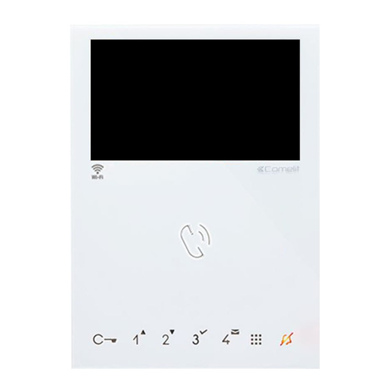
- Page 1 TECHNICAL MANUAL MYCOMELIT: THE APP FOR PROFESSIONALS MYCOMELIT, L'APP PER IL PROFESSIONISTA FREE DOWNLOAD Amazon, Alexa and all related logos are trademarks of Amazon.com, Inc. or its affiliates. Mini Hands-Free Wi-Fi Door Entry Monitor Art. 6741W - Art. 6741W/BM Passion.Technology.Design.
-
Page 2: Table Of Contents
Comelit Group S.p.A., for the systems, by qualified technical personnel. • Comelit Group S.p.A. accepts no liability for any purpose other than the intended use, or failure to observe the indications and warnings contained in this manual / instruction sheet. Comelit Group S.p.A. reserves the right to change the information provided in this manual / instruction sheet at any time and without prior notice. -
Page 3: Description
It allows operation of the new Comelit WiFree series of Wi-Fi home automation devices. It is also possible to control devices with different protocols, thereby integrating any third-party home automation system for controlling gates or outdoor lights, or for activating scenarios, etc. -
Page 4: Touch-Sensitive Buttons
Touch-sensitive buttons Description f Press and release the desired button once to activate the associated function. Wait for approx. 1 sec. before pressing the same button again; rapidly pressing the same button repeatedly will cancel the command which has just been sent. Audio activation Lock-release control [programmable]... -
Page 5: Technical Specifications
(codes with 13 ASCII digits or 26 hexadecimals) (codes with 13 ASCII digits or 26 hexadecimals) IP address assignment DHCP DHCP IoT connection to Comelit Cloud Firmware updating via Comelit Cloud IP protection rating IP30 IP30 Operating temperature (°) -
Page 6: Installation
Installation A user code (call code) must be assigned to the door entry monitor; to configure it simply set the S1 DIP-switches corresponding to the desired code to ON, in accordance with the “Addressing table”. Addressing table Code DIP-switch 1,2,3,7 2,4,6,7 1,3,4,8 5,6,8... -
Page 7: Building Mode, Kit Mode
10 x 6741W (/BM) units. Other 6741W (/BM) units should be set in Building mode! If there are more than 20 internal units, Kit mode is not possible; all 6741W (/BM) will therefore need to be set in Building mode! •... -
Page 8: Main And Secondary Door Entry Monitors
Main and secondary door entry monitors A single 6741W (/BM) door entry monitor can be installed for each user code (apartment); this will also be the only main door entry monitor 6741W (/BM) 1 2 3 4 1209 / 1210 / 1210A / 4888C / 4888CU Compatible secondary door entry monitors: art. -
Page 9: Surface Mounting
Surface mounting Before definitive installation of the door entry monitor, make sure the device has good Wi-Fi signal reception; the distance between the router and door entry monitor, and the construction materials used in the walls are factors that can affect signal quality. If the Wi-Fi signal is not strong enough to guarantee correct operation, a Wi-Fi repeater must be installed between the router and door entry monitor in order to boost the Wi-Fi signal received by the door entry monitor. -
Page 10: Removing The Door Entry Monitor
Removing the door entry monitor Removing / fitting the terminal < BACK... -
Page 11: Connections
Connections MONTANTE VIDEO ENTRY RISER VIDEOCITOFONICA 6741W 1214/2C 6741W/BM MONTANTE DAY/NIGHT FUNCTION CHIAMATA VIDEO ENTRY RISER VIDEOCITOFONICA FUORIPORTA CALL 20 m MAX - use a shielded cable for the connection and do not route the cables near heavy inductive loads or power cables (230V / 400V). -
Page 12: Button Configuration
It is possible to change the default configuration of the buttons by changing the positions of the S2 DIP-switches 1-2-3-4 on the rear of the door entry monitor to one of the combinations (B-P) suggested in the table below. All the buttons will change function. Standard configurations S2 Dip-switches Art. 6741W (/BM) DIP 1 DIP 2 DIP 3... -
Page 13: Advanced Configuration
Advanced configuration If the standard configuration settings do not reflect requirements, the buttons can be programmed differently by carrying out the steps below. After programming, set S2 DIP 1-2-3-4 (PROG) to ON. With these DIP settings, the buttons manage the programmed functions. - Page 14 5. Press and release the button to be associated with the function. » Correct procedure indication: the LED flashes for a few seconds and a confirmation tone sounds. 6. Exit programming mode by setting S2 DIP 6 to OFF. » LED switches off 7.
- Page 15 9. Return the S1 DIP-switch settings to their original combination. If you need to delete the intercom call code, proceed as follows: DIP-switches Take note of the Se the as shown in the figure. OK prog: OK prog: S1, S2 settings and restore them when programming is complete.
- Page 16 6. Exit programming mode by setting S2 DIP 6 to OFF. » LED switches off 7. Set S2 DIP-switches 1-2-3-4 to ON. 8. Return S1 DIP-switches to the original combination. Coded actuator: button configuration 1. Make a note of the S1 DIP-switch settings. 2.
- Page 17 Configuring the minimum range address set a code in accordance with the “Addressing table” on page Configuring the maximum range address set a code in accordance with the “Addressing table” on page Deleting the range 2 sec Enabling the range Disabling the range <...
-
Page 18: Configuration Via The Menu
“Link” function can be WiFree device operation configured. • Art. 6741W (/BM) must be connected to the internet in order to use this function! • Art. 6741W (/BM) must be paired with the Comelit app with version 5.6.0 or higher! -
Page 19: Create The Commands To Be Associated With The Buttons
Create the commands to be associated with the buttons Once the WiFree modules have been installed and configured via the Comelit WiFree app, in order to be able to control the devices using the enabled buttons you will need to create a “direct link” for each command to be associated. Different “direct links”... -
Page 20: Operating Third-Party Devices With Functions That Can Be Activated Via Url
DOOR ENTRY MONITORS an external light, to activate a scenario, etc. Program buttons • Art. 6741W (/BM) must be connected to the internet in order to use this function! Select • Art. 6741W (/BM) must be paired with the configure. -
Page 21: Changing The Ringtone
Changing the ringtone 1. Press and hold for 6 sec. » a confirmation tone is emitted » the LED flashes The procedure is only possible while the system is in standby; otherwise the LED will flash 4 times to inform the user that the system is busy. -
Page 22: System Performance And Layouts
1229A Maximum no. of internal units (including call repetition devices) with the same user code Maximum no. of internal units that can be powered by art. 1209 (up to 4 art. 6741W (/BM)) MODALITÀ KIT: 16 VIDEOCITOFONI/ ART. 1229A MAX... - Page 23 Single-family system 6741W 6741W/BM +6710 1 2 3 4 1 2 3 4 1209 110-240V 4893M Local door-opener button. Two-family system 1216 6721W 6721W/BM +6710 1 2 3 4 6741W 6741W/BM +6710 1 2 3 4 1214/2C 1 2 3 4...
- Page 24 1214/2C 1 2 3 4 1 2 3 4 1214/2C 6721W 6721W/BM +6710 1 2 3 4 6741W 1 2 3 4 6741W/BM +6710 1214/2C 1 2 3 4 1 2 3 4 1214/2C 1209 110-240V 4893M Local door-opener button.
- Page 25 Single-family system with 2 external entrance panels and switching device art. 1404 6741W 6741W/BM +6710 1 2 3 4 1 2 3 4 1404 1 2 3 4 1209 1209 1 2 3 4 1 2 3 4 110-240V 110-240V...
- Page 26 Single-family system with 3 external entrance panels 1404 1404 1 2 3 4 1 2 3 4 1 2 3 4 1 2 3 4 1 2 3 4 1 2 3 4 1209 1209 1209 4893M 4893M 4893M Local door-opener button. <...
-
Page 27: Diagrams For Systems With Power Supply Unit Art. 1210 Or 1210A
Diagrams for systems with power supply unit art. 1210 or 1210A Maximum no. of 6741W (/BM) units per apartment with the same user code Call repetition devices that can be used Art. 1229A Maximum no. of internal units (including call repetition devices) with the same user code and 2 (Fig. - Page 28 System with 1 external entrance panel 1216 6801W 6801W/BM 1214/2C 1214/2C 2738W 2738W/A 6750W 1214/2C 1 2 3 4 5 6 1214/2C 6741W 6721W 6701W 6701W/8 6741W/BM 6721W/BM + 6710 + 6710 6701W/BM + 6710 6601W/ 6601W/BM 1214/2C 230V 1210A...
- Page 29 System with 2 external entrance panels 1404 1 2 3 4 1 2 3 4 1 2 3 4 230V 230V 1210A 1210A R GND R GND NO NC NO NC UT2020 UT2010 (MAX 8) (MAX 8) UT9200 UT9200 Video entry riser. Local door-opener button.
-
Page 30: System Diagrams With Power Supply Unit Art. 4888C / 4888Cu
In systems powered by 4888C with a revision index between 021 and 052, up to 50 door entry monitors can be installed. • Power supply units 4888C (4888CU) with a revision index prior to 021 (014) are not compatible for use with 6741W (/BM), and should therefore be replaced. - Page 31 1212/B A single 6741W (/BM) door entry monitor can be installed for each user code; this will also be the only main door entry monitor. Up to 3 secondary door entry monitors can also be added art. 6601W, 6601W/BM, 6701W, 6701W/BM, 6701W/8, 6721W, 6721W/BM, 6801W, 6801W/BM.
- Page 32 1214/2C 2738W 2738W/A 1214/2C 6801W/ 6721W 6701W 6801W/BM 6721W/BM 6701W/8 +6710 6701W/BM +6710 1214/2C 1 2 3 4 5 6 6741W 1214/2C 6741W/BM +6710 1214/2C 4888C 230V 1595 120-230 V UT1020 SE NO NC UT9200 1595 1595 120-230 V 120-230 V...
- Page 33 System with 2 external entrance panels 4888C 1224A ~ 230V 1 2 3 4 1 2 3 4 1595 1595 120-230 V 120-230 V SE NO NC SE NO NC UT1020 UT1020 UT9200 UT9200 Video entry riser. Local door-opener button. (20 m max.) Variant for porter switchboard connection 4888C 230V...
- Page 34 1595 120-230 V SE NO NC UT1020 UT9200 Video entry riser. Local door-opener button. (20 m max.) Art. 6741W (/BM) and a secondary door entry monitor in branch connection 1216 6741W 1 2 3 4 6741W/BM + 6710 MAIN PRINCIPALE...
-
Page 35: System Performance And Layouts
Art. 6741W (/BM) and a secondary door entry monitor 6721W (/BM) in cascade connection 1216 6741W 1 2 3 4 1 2 3 4 6741W/BM + 6710 PRINCIPALE MAIN 1214/2C Compatible secondary door entry monitors: art. 6601W, 6601W/BM, 6701W, 6701W/BM, 6701W/8, 6721W, 6721W/BM, 6801W, 6801W/BM. - Page 36 C E R T I F I E D M A N A G E M E N T S Y S T E M S w w w . c o m e l i t g r o u p . c o m Via Don Arrigoni, 5 - 24020 Rovetta (BG) - Italy...