Comelit 6721W Technical Manual
Mini handsfree
Hide thumbs
Also See for 6721W:
- Technical manual (25 pages) ,
- Instruction manual (11 pages) ,
- Technical manual (16 pages)
Table of Contents
Advertisement
Advertisement
Table of Contents

Related Manuals for Comelit 6721W


Summary of Contents for Comelit 6721W
- Page 1 TECHNICAL MANUAL Mini handsfree art. 6721W(/BM) Passion.Technology. Design.
-
Page 2: Table Of Contents
Warning Intended use This Comelit product was designed for use in the creation of audio and video communication systems in residential, commercial or industrial settings and in public buildings or buildings used by the public. Installation All activities connected to the installation of Comelit products must be carried out by qualified technical personnel, with careful observation of the indications provided in the Manuals / Instruction sheets supplied with those products. -
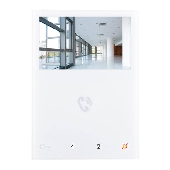
Page 3: Monitor Description
Monitor description 1. Brightness control f To increase the value, turn clockwise 2. Loudspeaker volume control f To increase the value, turn clockwise 3. 4.3’’LCD colour screen 4. Call volume adjustment (high - medium - low) 5. Soft-touch keys 6. Speaker and audio activation key 7. -
Page 4: Soft-Touch Key Description
(idle): automatic answer activated continuous flashing: incoming call The monitor Art. 6721W is designed for use in colour systems, in the SB2 section downstream of Art. 4888C, or in systems without mixer, such as the system with 2-wire KIT or Art. 1210. -
Page 5: Installation
Installation 115 mm optional fixing... -
Page 6: Removing / Fitting The Terminal
Removing / Fitting the terminal Fitting upgrade KIT Art. 6734W (to remove) -
Page 7: Operation
» (ACTIVATION) + audio LED with FIXED ILLUMINATION » (DEACTIVATION) + audio LED OFF Monitor configuration Standard configuration for soft-touch keys DIP S2 Art. 6721W(/BM) + Art. 6734 DIP 1 DIP 2 DIP 3 DIP 4 INTb INTb INTb INTb... -
Page 8: Advanced Monitor Configuration
Advanced monitor configuration Warning If the default settings (see table on page 7) do not reflect requirements, the keys can be programmed differently by carrying out the steps below. At the end, set S2 DIP switches 1-2-3-4 to the combination 1111 (PROG setting in the configuration tables on pages 8-12). -
Page 9: Programming Buttons For Intercom Call
Programming buttons for intercom call DIP S2 Art. 6721W(/BM) + Art. 6734 DIP S1 DIP 1 DIP 2 DIP 3 DIP 4 INTb INTb INTb ADDRESS INTb INTb INTb PROG Example 1 - all systems (INCLUDING KITS!) - General intercom... -
Page 10: Direct Programming Of Intercom Call
Direct programming of intercom call Allows direct programming of intercom call via the internal units. √ Requires 2 operators Step 1: enter programming mode Operator 1 and Operator 2 carry out the following procedures on 2 internal units: 1. Set S2 DIP switches 1-2 -3-4 to the combination 1111 2. -
Page 11: Programming Keys For Generic Or Coded Actuator
Programming keys for generic or coded actuator DIP S2 Art. 6721W(/BM) + Art. 6734 DIP S1 DIP 1 DIP 2 DIP 3 DIP 4 ADDRESS PROG Example: on a monitor with user code 5, P1 programming = generic actuator, P2 = coded actuator (code 125) Take note of the DIP-switch settings 1. -
Page 12: Programming Buttons For Other Functions
Programming buttons for other functions DIP S2 Art. 6721W(/BM) + Art. 6734 DIP 1 DIP 2 DIP 3 DIP 4 NULL NULL NULL NULL NULL NULL PROG Legend Lock- release Self-ignition Main switchboard call – not for use in systems with KIT Secondary switchboard call –... -
Page 13: Programming Range
Programming range Take note of the S2, S1 setting and restore it when programming is complete Carry out steps 1 to 4 S2 DIP Range minimum 1 2 3 4 5 6 address 0 0 0 0 1 0 set code, TAB. A on page Range maximum address... -
Page 14: Programming Reset
Programming reset Factory settings: • Button functions for the S2 DIP switch 1-2-3-4 combination; • Intercom address absent; • Range function and min./max. addresses absent; DIP OFF • Ringtone reset. Take note of the S2, S1 setting and restore it when programming is complete S2 DIP DIP ON 1 2 3 4 5 6... -
Page 15: Riser Addresses
Riser addresses TAB. A Dip switch Dip switch Dip switch Dip switch Dip switch Dip switch Dip switch Dip switch Code Code Code Code Code Code Code Code 1,2,3,4,5 1,3,4,5,6 1,2,4,5,7 1,4,5,6,7 1,2,3,5,8 1,3,5,6,8 1,2,5,7,8 2,3,4,5,6 3,4,5,7 2,4,5,6,7 4,5,8 2,3,5,6,8 3,5,7,8 1,2,3,4,5,6 1,3,4,5,7... -
Page 16: Operating Distances With Art. 4888C
Connect only one call repetition device for each internal unit. 1216 6721W 1214/2C 4888C A MAX B MAX F MAX H MAX Comelit Art. 4577/4579 1 mm2 (Ø 1,2 mm AWG 17) 200 m 200 m 50 m 100 m (655 feet) (655 feet) (165 feet) (330 feet) UTP5 cat. -
Page 17: Wiring Diagrams With Art. 4888C
Wiring diagrams with Art. 4888C System with Art. 4888C: 1 Ikall series external unit 1216 1214/2C 6721W 1234 67 6721W/BM+6710 1214/2C 1234 67 2628/ 2638 1214/2C 6721W 1234 67 6721W/BM+6710 2 3 4 4888C 230V 1595 120-230 V 33436 4680KC... -
Page 18: System With Art. 4888C: 2 Main Monitors In Cascade Connection
System with Art. 4888C: 2 main monitors in cascade connection 6721W 6721W 1216 6721W/BM 6721W/BM +6710 +6710 1234 67 1234 67 1214/2C SB2/A19MINICV System with Art. 4888C: 2 main monitors and 1 secondary monitor in branch connection 6721W 1216 6721W/BM... -
Page 19: Operating Distances With Kit 8461V
1209 1214/2C 1209 4893 4893 A MAX B MAX Comelit Art. 4577/4579 1 mm2 (Ø 1,2 mm AWG 17) 200 m 100 m (655 feet) (330 feet) UTP5 cat. 5 0,2 mm2 (Ø 0,5 mm AWG 24) 100 m 60 m... -
Page 20: Operating Distances With Art. 1210
4681 4681 A MAX B MAX C MAX H MAX Comelit Art. 4577/4579 1 mm2 (Ø 1,2 mm AWG 17) (850 feet) (425 feet) (425 feet) (164 feet) UTP5 cat. 5 0,2 mm2 (Ø 0,5 mm AWG 24) (260 feet) -
Page 21: Wiring Diagrams With Kit 8461V And Art.1210
Wiring diagrams with KIT 8461V and Art.1210 KIT 8461V: standard single-family system 6721W 6721W/BM +6710 1234 67 110-240V 30 Vdc 30 Vdc 1209 4893 MNVK/039QC Local door-opener button System with Art. 1210 1216 6721W 6721W/BM +6710 1214/2C 6721W 6721W/BM 1234 67... -
Page 22: Kit 8461V Or System With Art. 1210: Secondary Monitor In Branch Connection
1234 67 1234 67 6721W 6721W 6721W 6721W/BM 6721W/BM +6710 6721W/BM +6710 1209 / 1210 SB2/A23MINICV Floor door call connection variant If there are a number of door-entry phones or monitor brackets with the same user code, connect the CFP button to one only; all the devices will ring simultaneously. - Page 24 C E R T I F I E D M A N A G E M E N T S Y S T E M S w w w . c o m e l i t g r o u p . c o m Via Don Arrigoni, 5 - 24020 Rovetta (BG) - Italy...