Comelit 6721W Technical Manual
Simplebus2 mini hands-free door entry monitor
Hide thumbs
Also See for 6721W:
- Technical manual (25 pages) ,
- Instruction manual (11 pages) ,
- Technical manual (24 pages)

Related Manuals for Comelit 6721W


Summary of Contents for Comelit 6721W
- Page 1 TECHNICAL MANUAL Simplebus2 Mini hands-free door entry monitor Art. 6721W - Art. 6721W/BM Passion.Technology.Design.
-
Page 2: Table Of Contents
Warning Intended use This Comelit product has been designed and manufactured for use in the creation of audio and video communication systems in residential, commercial, industrial and public buildings. Installation All activities connected to the installation of Comelit products must be carried out by qualified technical personnel, with careful observation of the indications provided in the Manuals / Instruction sheets supplied with those products. -
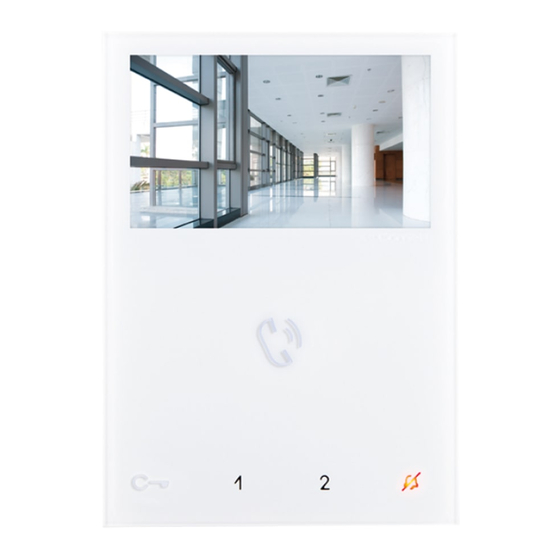
Page 3: Description
Description 6721W Wall-mounted hands-free monitor with full-duplex audio and 4.3” / 16:9 colour screen. Allows brightness level and ringtone volume adjustment; the ringtone can be customised by selecting one of several different melodies. With 5 touch-sensitive buttons with LED backlighting for audio operation, lock-release, self activation, switchboard call and Privacy function, plus a door status indicator LED. -
Page 4: Legend: Buttons And Indicator Leds
Legend: buttons and indicator LEDs f Press the desired button once to activate the associated function. Wait for approximately 1 sec. before pressing the same button again. Pressing the same button several times in quick succession will cancel the command. Description of buttons Indicator LED description Flashing LED: incoming call... -
Page 5: Technical Specifications
Technical specifications GENERAL DATA 6721W 6721W/BM Product height (mm) Product width (mm) Product depth (mm) Product weight (g) Product colour White RAL9003 White RAL9003 Material Surface mounting Desk base mounting Yes, with specific accessory Yes, with specific accessory COMPATIBLE SYSTEMS Simplebus2 audio/video with power supply unit art. -
Page 6: Installation
Installation 115 mm fissaggio opzionale FACILITATED OPENING... -
Page 7: Removing/Fitting The Terminal
Removing/Fitting the Terminal Connections VIDEO ENTRY SYSTEM MONTANTE RISER VIDEOCITOFONICA 6721W 1214/2C 6721W/BM 20 m MAX - Use shielded cable for the connection and do not route the cables in the vicinity of heavy inductive loads or power supply cables (230 V/400 V). -
Page 8: Button Configuration
Button configuration By default the buttons control the functions in row A (“Standard configuration” table). It is possible to change the default configuration of the buttons by changing the positions of S2 DIP-switches 1-2-3-4 on the rear of the door entry monitor to one of the combinations (B-P) suggested in the table. -
Page 9: Advanced Configuration
Advanced configuration If the standard configuration settings (A-P) do not reflect requirements, the buttons can be programmed differently by carrying out the steps below. After programming, set S2 DIP-switches 1-2-3-4 (PROG) to ON. With these DIP-switch settings, the buttons manage the programmed functions. The buttons that are NOT programmed control the functions in row A (“Standard configuration”... -
Page 10: Selective Intercom Address
Selective intercom address TABLE B Code S1 DIP-switch ON Code S1 DIP-switch ON Code S1 DIP-switch ON Assigning selective address (Steps only need to be carried out for “Intercom call to selective address” programming) Take note of the S1: Set an address. S2: Set the DIP-switches as S1, S2 settings and (Table B) -
Page 11: Coded Actuator: Button Programming
Coded actuator: button programming 1. Take note of the S1 DIP-switch settings. set S2 o enter programming mode, DIP-switch 6 to ON. » the LED flashes Refer to the table “Basic configuration” to identify a DIP-switch combination in which the actuator function (ACT) corresponding to the button you want to program appears, then set the S2 DIP-switches. -
Page 12: Changing The Ringtone
Changing the ringtone 1. Press and hold for 6 sec. » a confirmation tone is emitted » the LED flashes √ the procedure can only take place while the system is in standby; otherwise the LED will flash 4 times to inform the user that the system is busy 2. -
Page 13: Addressing Table
Addressing table DIP-switch Code * NOTE: Code 240 is reserved for the porter switchboard 1,2,3,4,5 1,3,4,5,6 1,2,4,5,7 1,4,5,6,7 1,2,3,5,8 1,3,5,6,8 1,2,5,7,8 2,3,4,5,6 3,4,5,7 2,4,5,6,7 4,5,8 2,3,5,6,8 3,5,7,8 1,2,3,4,5.6 1,3,4,5,7 1,2,4,5,6.7 1,4,5,8 1,2,3,5,6.8 1,3,5,7,8 2,3,4,5,7 3,4,5,6,7 2,4,5,8 4,5,6,8 2,3,5,7,8 1,2,6 1,2,3,4,5.7 1,3,4,5,6.7 1,2,4,5,8 1,4,5,6,8...