Comelit 6721W/BM Technical Manual
Mini handsfree monitor
Hide thumbs
Also See for 6721W/BM:
- Technical manual (24 pages) ,
- Instruction manual (11 pages) ,
- Technical manual (13 pages)

Related Manuals for Comelit 6721W/BM


Summary of Contents for Comelit 6721W/BM
- Page 1 TECHNICAL MANUAL Mini Handsfree monitor Art. 6721W - Art. 6721W/BM Passion.Technology. Design.
-
Page 2: Table Of Contents
Table of contents Warning Monitor description ................. 3 Description of buttons ................4 Indicator LED description................4 Technical specifications ..............5 Installation ..................7 Removing / Fitting the terminal ..............8 Connections ..................8 Monitor configuration ..............9 Configuration of main and secondary internal units ......9 Power supply configuration and management ........9 Keys configuration ................ -
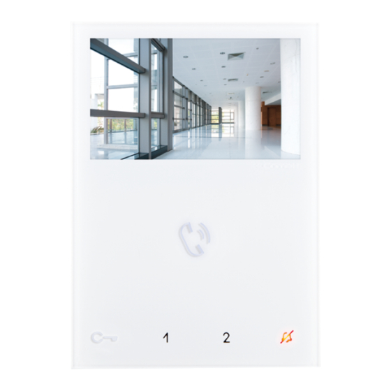
Page 3: Monitor Description
Art. 6734W) • Article 6721W/BM is a colour monitor equipped as standard with 5 buttons (3 additional buttons can be added with the accessory Art. 6734W) and magnetic induction audio amplification. Not supplied with backplate 6710. 1. Brightness control f To increase the value, turn clockwise 2. -
Page 4: Description Of Buttons
Description of buttons f Press the desired button once to activate the associated function. Wait for approximately 1 sec. before pressing the same button again. AUDIO ACTIVATION KEY Press the button to answer an incoming call. HANDS-FREE MODE ACTIVATION/DEACTIVATION On receipt of a call, the audio will be activated automatically. f A long press enables/disables the Hands-Free mode (10 s.) LOCK RELEASE KEY Use this key to open the corresponding door lock. -
Page 5: Technical Specifications
Technical specifications MAIN SPECIFICATIONS 6721W 6721W/BM Audio/video system Wall-mounted Desk base-mounted Hands-free function Audio amplification Type of display Display size (inches) 4,3" 16/9 4,3" 16/9 Display resolution (H x V) 480x272pixel 480x272pixel B/W or colour display Color Colors Product colour... - Page 6 TECHNICAL SPECIFICATIONS 6721W 6721W/BM Power supply voltage 22÷28Vdc 22÷28Vdc Absorption Maximum current absorption (mA) Microphone 6mm omni-direction 6mm omni-direction Loudspeaker 36mm 40Ohm 1W 36mm 40Ohm 1W IP Rating Operating temperature (°C) -5÷40 -5÷40 Relative humidity for operation 25 - 75 %...
-
Page 7: Installation
Installation 115 mm optional fixing EASY OPENING... -
Page 8: Removing / Fitting The Terminal
Removing / Fitting the terminal Connections VIDEO ENTRY SYSTEM RISER 6721W 1214/2C FLOOR DOOR CALL VIDEO ENTRY SYSTEM RISER 20 m MAX - Use shielded cable for the connection and do not route the cables in the vicinity of heavy inductive loads or power supply cables (230V/400V). -
Page 9: Monitor Configuration
Monitor configuration Configuration of main and secondary internal units f To configure an internal unit as the main unit, set DIP 8 of S2 to OFF f To configure an internal unit as a secondary unit, set DIP 8 of S2 to ON DIP 8 DIP 8 (S2) -
Page 10: Keys Configuration
Keys configuration By default the buttons control the functions in row A (“Basic configuration” table). It is possible to change the default configuration of the keys by changing the positions of the S2 DIP switches 1-2-3-4 on the rear of the monitor to one of the combinations (B-P) proposed in the table. All the keys will change function. Basic configuration S2 DIP-switch Mini Handsfree... -
Page 11: Advanced Configuration
Advanced configuration If the basic configuration settings do not reflect requirements, the buttons can be programmed differently by carrying out the steps below. After programming, set S2 DIP switches 1-2-3-4 (PROG) to ON. With these DIP-switch settings, the buttons control the programmed functions. -
Page 12: Intercom Call To Selective Address: Button Programming
Intercom call to selective address: button programming √ It is necessary to carry out the 3 operations described in the paragraph "Assigning a selective address to the monitor". 1. Take note of the S1 DIP-switch settings. 2. To enter programming mode, set S2 DIP switch 6 to ON. »... -
Page 13: Generic Actuator, Addressable Actuator
Generic actuator, Addressable actuator Generic actuator: button programming 1. Take note of the S1 DIP-switch settings. 2. To enter programming mode, set S2 DIP switch 6 to ON. » the Privacy LED switches on 3. Refer to the table “Basic configuration” and set on S2 a combination in which the Example: actuator function (ACT) associated with the buttons you wish to program appears. -
Page 14: Other Functions: Button Programming
Other functions: button programming 1. To enter programming mode, set S2 DIP switch 6 to ON. » the Privacy LED switches on 2. Refer to the table “Basic configuration” and set on S2 a combination in which the Example: function associated with the buttons you wish to program appears. 3. -
Page 15: Changing Monitor Ringtones
Changing monitor ringtones 1. Press and hold for 6 sec. » a confirmation tone will sound » the Privacy LED will flash to indicate "programming" mode. √ the procedure can only take place while the system is in standby; otherwise the Privacy LED will flash 4 times to inform the user that the system is engaged. -
Page 16: Addressing Table
Addressing table NOTE: code 240 is reserved for the porter switchboard DIP switch Code 1,2,3,4,5 1,3,4,5,6 1,2,4,5,7 1,4,5,6,7 1,2,3,5,8 1,3,5,6,8 1,2,5,7,8 2,3,4,5,6 3,4,5,7 2,4,5,6,7 4,5,8 2,3,5,6,8 3,5,7,8 1,2,3,4,5,6 1,3,4,5,7 1,2,4,5,6,7 1,4,5,8 1,2,3,5,6,8 1,3,5,7,8 2,3,4,5,7 3,4,5,6,7 2,4,5,8 4,5,6,8 2,3,5,7,8 1,2,6 1,2,3,4,5,7 1,3,4,5,6,7 1,2,4,5,8 1,4,5,6,8...