Comelit 6741W Technical Manual
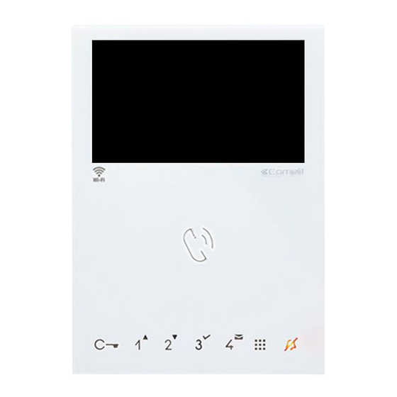
Mini hands-free door entry monitor
Hide thumbs
Also See for 6741W:
- Technical manual (36 pages) ,
- Operating manual (20 pages) ,
- User manual (10 pages)

Related Manuals for Comelit 6741W


Summary of Contents for Comelit 6741W
- Page 1 TECHNICAL MANUAL Amazon, Alexa and all related logos are trademarks of Amazon.com, Inc. or its affiliates. Mini Hands-free Door Entry Monitor Art. 6741W - Art. 6741W/BM Passion.Technology.Design.
-
Page 2: Warning
• any purpose other than the intended use, • failure to observe the indications and warnings contained in this Manual / Instruction sheet. Comelit Group S.p.A. reserves the right to change the information provided in this Manual / Instruction Sheet at any time and without prior notice. -
Page 3: Table Of Contents
Kit Art. 8461V: basic single-family system with Art. 1209 ....28 Art. 6741W (/BM) and a secondary door entry monitor in branch connection ....................29 Art. 6741W (/BM) and a secondary door entry monitor 6721W (/BM) in cascade connection ................29 System performance and layouts ..........30... -
Page 4: Description
Description Hands-free Mini Wi-Fi door entry monitor for Simplebus 2 system. When used in conjunction with the Comelit app, available to download free of charge from the Google and Apple stores, and/or the Alexa/Ecoshow/Google voice assistants, it can be used to answer calls directly from your smartphone/tablet/assistant device, both locally and remotely. -
Page 5: Touch-Sensitive Buttons
Touch-sensitive buttons Description f Press and release the desired button once to activate the associated function. Wait for approx. 1 sec. before pressing the same button again; rapidly pressing the same button repeatedly will cancel the command which has just been sent. Audio activation Lock-release control [programmable]... -
Page 6: Operation
Operation When Art. 6741W (/BM) is connected to the power supply, the LEDs will flash: wait for them to switch off (approx. 40 sec) before starting to use the device. Answering an incoming call Press the touch-sensitive audio activation button to answer the incoming call. -
Page 7: Technical Specifications
Technical specifications 6741W 6741W/BM GENERAL DATA Product height (mm) Product width (mm) Product depth (mm) Product weight (g) Product colour White RAL9003 White RAL9003 Material Surface mounting Desk base mounting Yes, with specific accessory Yes, with specific accessory COMPATIBLE SYSTEMS Simplebus 2 audio/video with power supply unit Art. - Page 8 (codes with 13 ASCII digits or (codes with 13 ASCII digits or 26 hexadecimals) 26 hexadecimals) IP address assignment DHCP DHCP IoT connection to Comelit Cloud Firmware updating via Comelit Cloud ENVIRONMENTAL AND CONFORMITY SPECIFICATIONS IP protection rating IP30 IP30 Operating temperature (°C)
-
Page 9: Installation
Installation Before definitive installation of the door entry monitor, make sure the device has good Wi-Fi signal reception; the distance between the router and door entry monitor, and the construction materials used in the walls are factors that can affect signal quality. If the Wi-Fi signal is not strong enough to guarantee correct operation, a Wi-Fi repeater must be installed between the router and door entry monitor in order to boost the Wi-Fi signal received by the door entry monitor. -
Page 10: Removing The Door Entry Monitor
Removing the door entry monitor Removing / fitting the terminal... -
Page 11: Connections
Connections VIDEO ENTRY SYSTEM RISER 6741W 1214/2C 6741W/BM VIDEO ENTRY FLOOR DOOR SYSTEM RISER CALL INPUT 20 m MAX - Use shielded cable for the connection and do not route the cables in the vicinity of heavy inductive loads or power supply cables (230 V/400 V). -
Page 12: Door Entry Monitor Setup
For correct power supply management, set DIP 7 (S2) according to the table. With Art. 6741W with a revision index [RR] greater than or equal to 12 and with Art. 6741W/BM with a revision index [RR] greater than or equal to 10: DIP 7 of S2 should always be left in ON (default), even in systems with 4888C and 4888CU. -
Page 13: Main And Secondary Door Entry Monitors
Main and secondary door entry monitors A single 6741W (/BM) door entry monitor can be installed for each user code; this will also be the only main door entry monitor 6741W 1 2 3 4 4888C / 4888CU / 1210 / 1210A / 1209... -
Page 14: Addressing Table
Addressing table Dip switch Code 1,2,3,4,5 1,3,4,5,6 1,2,4,5,7 1,4,5,6,7 1,2,3,5,8 1,3,5,6,8 1,2,5,7,8 2,3,4,5,6 3,4,5,7 2,4,5,6,7 4,5,8 2,3,5,6,8 3,5,7,8 1,2,3,4,5.6 1,3,4,5,7 1,2,4,5,6.7 1,4,5,8 1,2,3,5,6.8 1,3,5,7,8 2,3,4,5,7 3,4,5,6,7 2,4,5,8 4,5,6,8 2,3,5,7,8 1,2,6 1,2,3,4,5.7 1,3,4,5,6.7 1,2,4,5,8 1,4,5,6,8 1,2,3,5,7.8 2,3,4,5,6.7 3,4,5,8 2,4,5,6,8 4,5,7,8 1,2,3 1,3,6 1,2,7 1,6,7... -
Page 15: Button Configuration
It is possible to change the default configuration of the buttons by changing the positions of the S2 DIP 1-2-3-4 on the rear of the door entry monitor to one of the combinations (B-P) proposed in the table. All the buttons will change function. Basic configuration S2 Dip-switches Mini 6741W / 6741W/BM DIP 1 DIP 2 DIP 3... -
Page 16: Press And Hold Buttons (Disabled By Default)
Press and hold buttons (disabled by default) Pressing and holding keys adds further functions to the door entry monitor. Carry out the procedure described below to enable - or disable, depending on the factory setting - the press and hold feature: √... -
Page 17: Advanced Configuration
Advanced configuration If the standard configuration settings do not reflect requirements, the buttons can be programmed differently by carrying out the steps below. After programming, set S2 DIP 1-2-3-4 (PROG) to ON. With these DIP settings, the buttons manage the programmed functions. -
Page 18: Intercom Call To Selective Address: Button Programming
Intercom call to selective address: button programming √ It is necessary to carry out the 3 steps described in the paragraph "Assigning a selective address to the door entry monitor". 1. Take note of the S1 DIP-switch settings. 2. To enter programming mode, set S2 DIP 6 to ON. »... -
Page 19: Generic Actuator, Coded Actuator
Generic actuator, coded actuator Generic actuator: button programming 1. Take note of the S1 DIP-switch settings. 2. To enter programming mode, set S2 DIP 6 to ON. » the LED flashes 3. Refer to the table “Basic configuration” and set on S2 a combination in which the Example: actuator function (ACT) associated with the buttons you wish to program appears. -
Page 20: Remote Camera Module
Remote camera module Remote camera module with generic address: button programming 1. Take note of the S1 DIP-switch settings. 2. To enter programming mode, set S2 DIP 6 to ON. » the LED flashes 3. Refer to the table “Basic configuration” and on S2 set the combination in which the Example: Remote camera module with generic address (cAMG) appears. -
Page 21: Other Functions: Button Programming
Other functions: button programming 1. To enter programming mode, set S2 DIP 6 to ON. » the LED flashes 2. Refer to the table “Basic configuration” and set on S2 a combination in which the Example: function associated with the buttons you wish to program appears. 3. -
Page 22: Changing Door Entry Monitor Ringtones
Changing door entry monitor ringtones 1. Press and hold for 6 sec. » a confirmation tone will sound » the LED will flash to indicate "programming" mode. √ the procedure can only take place while the system is in standby; otherwise the LED will flash 4 times to inform the user that the system is busy 2. -
Page 23: Art. 6741W (/Bm) In Systems Powered By Art. 4888C/4888Cu
In systems powered by 4888C with a revision index between 021 and 052, up to 50 door entry monitors can be installed. • Power supply units 4888C (4888CU) with a revision index prior to 021 (014) are not compatible for use with 6741W (/BM), and should therefore be replaced. -
Page 24: Operating Distances
MONITOR / ART. 1229A 4888CU UT1020 1595 A max B max F max H max Comelit Art. 4577/4579 1 mm2 (Ø 1.2 mm AWG 17) 200 m 200 m 50 m 100 m (655 feet) (655 feet) (165 feet) (330 feet) UTP5 cat. -
Page 25: Art. 6741W (/Bm) In Systems Powered By Art. 1210/1210A
Art. 6741W (/BM) in systems powered by Art. 1210/1210A Max. number of riser-powered 6741W (/BM) with the same user code Call repetition devices that can be used 1229A Maximum number of internal units (including call repetition devices) with the 2 in kit mode... -
Page 26: Art. 6741W (/Bm) In Kit Systems Art. 8451V
Art. 6741W (/BM) in Kit systems Art. 8451V Max. number of riser-powered 6741W (/BM) with the same user code Call repetition devices that can be used 1229A Maximum number of internal units (including call repetition devices) with the same user code Maximum number of internal units that can be powered by Art. -
Page 27: Wiring Diagrams
Wiring diagrams System with Art. 4888C / 4888CU 1216 6741W 6741W/BM +6710 6741W 6741W/BM +6710 1214/2C 1 2 3 4 1 2 3 4 1214/2C 4888C ~230V 4888CU 1595 120-230 V NO NC UT1020 UT9200 20 m MAX. Local door-opener button... -
Page 28: System With Art. 1210/1210A
System with Art. 1210/1210A 1216 6741W 6741W/BM +6710 6741W 1214/2C 6741W/BM +6710 1 2 3 4 1 2 3 4 1214/2C 230V 1210 1210A R GND NO NC 20 m MAX. Local door-opener button UT2020 UT9200 Kit Art. 8461V: basic single-family system with Art. 1209... -
Page 29: Art. 6741W (/Bm) And A Secondary Door Entry Monitor In Branch Connection
6741W/BM + 6710 1214/2C 1 2 3 4 1214/2C “ Compatible secondary door entry monitors” Art. 6741W (/BM) and a secondary door entry monitor 6721W (/BM) in cascade connection 1216 6741W 1 2 3 4 1 2 3 4 6741W/BM+6710 1214/2C “... -
Page 30: System Performance And Layouts
System performance and layouts For further information of system performance and to view installation layouts, click on the system type that best meets your requirements: • Simplebus2 audio/video with 1210/1210A • Simplebus2 audio/video with 4888C • Audio/Video kit... - Page 31 C E R T I F I E D M A N A G E M E N T S Y S T E M S w w w . c o m e l i t g r o u p . c o m Via Don Arrigoni, 5 - 24020 Rovetta (BG) - Italy...